Page 1462 of 1529

NAVIGATION SYSTEM
DESCRIPTION AND OPERATION 87-9
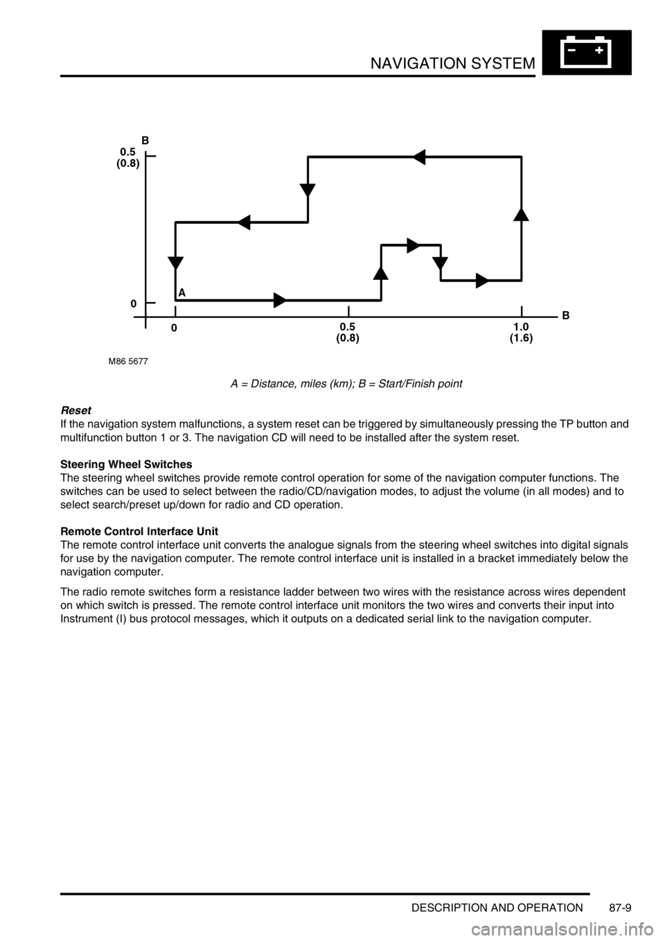
A = Distance, miles (km); B = Start/Finish point
Reset
If the navigation system malfunctions, a system reset can be triggered by simultaneously pressing the TP button and
multifunction button 1 or 3. The navigation CD will need to be installed after the system reset.
Steering Wheel Switches
The steering wheel switches provide remote control operation for some of the navigation computer functions. The
switches can be used to select between the radio/CD/navigation modes, to adjust the volume (in all modes) and to
select search/preset up/down for radio and CD operation.
Remote Control Interface Unit
The remote control interface unit converts the analogue signals from the steering wheel switches into digital signals
for use by the navigation computer. The remote control interface unit is installed in a bracket immediately below the
navigation computer.
The radio remote switches form a resistance ladder between two wires with the resistance across wires dependent
on which switch is pressed. The remote control interface unit monitors the two wires and converts their input into
Instrument (I) bus protocol messages, which it outputs on a dedicated serial link to the navigation computer.
Page 1470 of 1529
NAVIGATION SYSTEM
DESCRIPTION AND OPERATION 87-17
GPS Antenna
The GPS antenna is installed on the rear of the roof, on the vehicle centreline. A diplexer unit on the underside of the
GPS antenna amplifies the radio signals received from the GPS satellites and transmits them through a co-axial cable
to the navigation computer for processing.
Display Unit
The display unit is integrated into the front stowage pocket, above the rear view mirror. The display unit is a colour
Liquid Crystal Display (LCD) that shows the programming menus, route guidance and traffic information. The display
illumination level automatically dims for night time viewing when the exterior lights are switched on.
Page 1472 of 1529
NAVIGATION SYSTEM
DESCRIPTION AND OPERATION 87-19
Trafficmaster Monitor ECU
The Trafficmaster monitor ECU is installed underneath the CD autochanger, below the RH front seat. The
Trafficmaster monitor ECU processes the traffic flow data from the Trafficmaster antenna and combines it with data
from the navigation computer to display on the display unit.
Trafficmaster Antenna
The Trafficmaster antenna is installed in the fascia, on the rear of the instrument pack. The antenna receives radio
signals containing the data relayed from the traffic flow sensors, and transmits the information on a hardwired
connection to the Trafficmaster monitor ECU.
Page 1475 of 1529

NAVIGATION SYSTEM
87-22 DESCRIPTION AND OPERATION
On-Board Monitor (Display Unit)
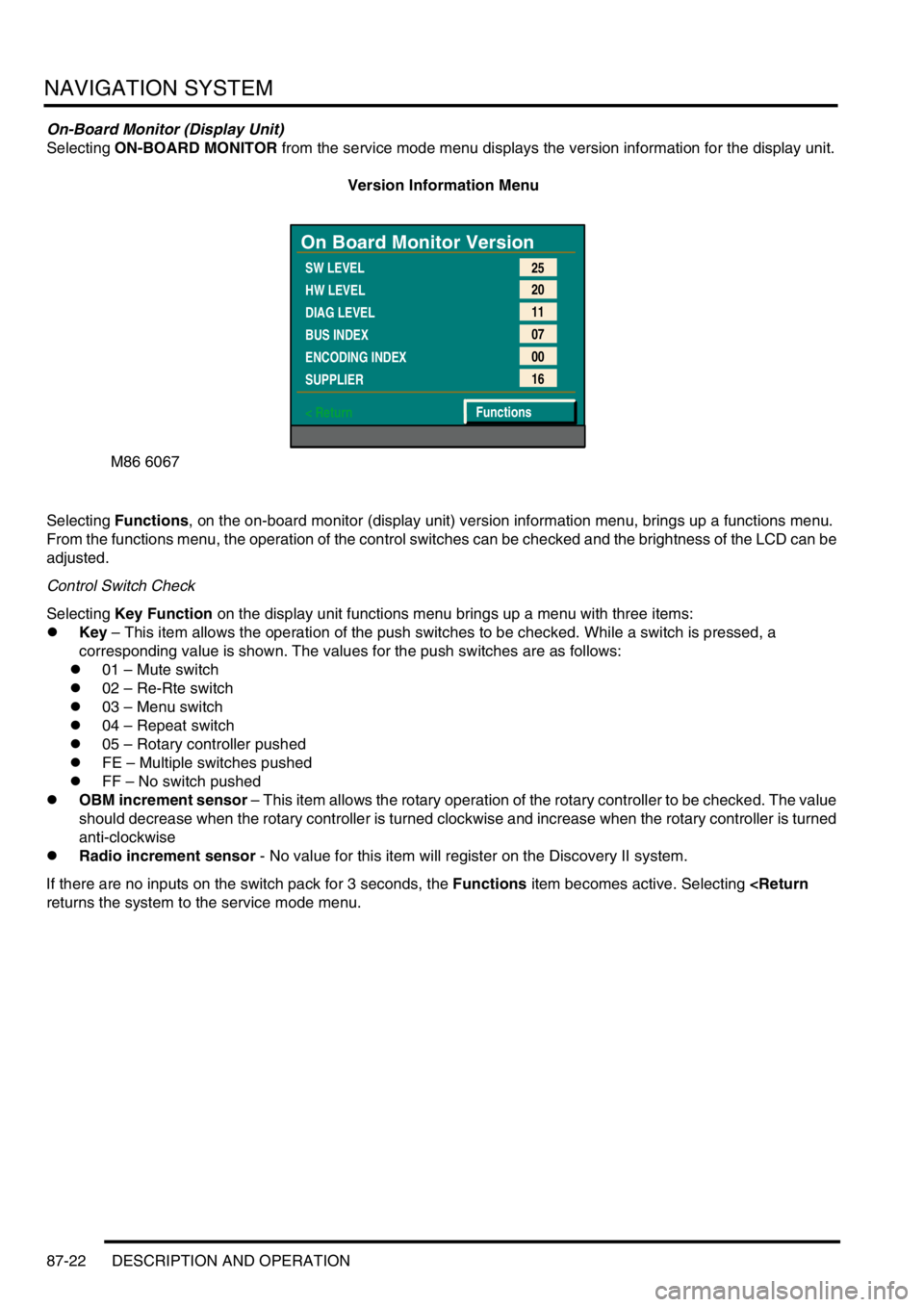
Selecting ON-BOARD MONITOR from the service mode menu displays the version information for the display unit.
Version Information Menu
Selecting Functions, on the on-board monitor (display unit) version information menu, brings up a functions menu.
From the functions menu, the operation of the control switches can be checked and the brightness of the LCD can be
adjusted.
Control Switch Check
Selecting Key Function on the display unit functions menu brings up a menu with three items:
lKey – This item allows the operation of the push switches to be checked. While a switch is pressed, a
corresponding value is shown. The values for the push switches are as follows:
l01 – Mute switch
l02 – Re-Rte switch
l03 – Menu switch
l04 – Repeat switch
l05 – Rotary controller pushed
lFE – Multiple switches pushed
lFF – No switch pushed
lOBM increment sensor – This item allows the rotary operation of the rotary controller to be checked. The value
should decrease when the rotary controller is turned clockwise and increase when the rotary controller is turned
anti-clockwise
lRadio increment sensor - No value for this item will register on the Discovery II system.
If there are no inputs on the switch pack for 3 seconds, the Functions item becomes active. Selecting
returns the system to the service mode menu.
M86 6067
On Board Monitor Version
SW LEVEL
HW LEVEL
DIAG LEVEL
BUS INDEX
ENCODING INDEX
SUPPLIER
< Return25
20
11
07
00
16
Functions
Page 1476 of 1529

NAVIGATION SYSTEM
DESCRIPTION AND OPERATION 87-23
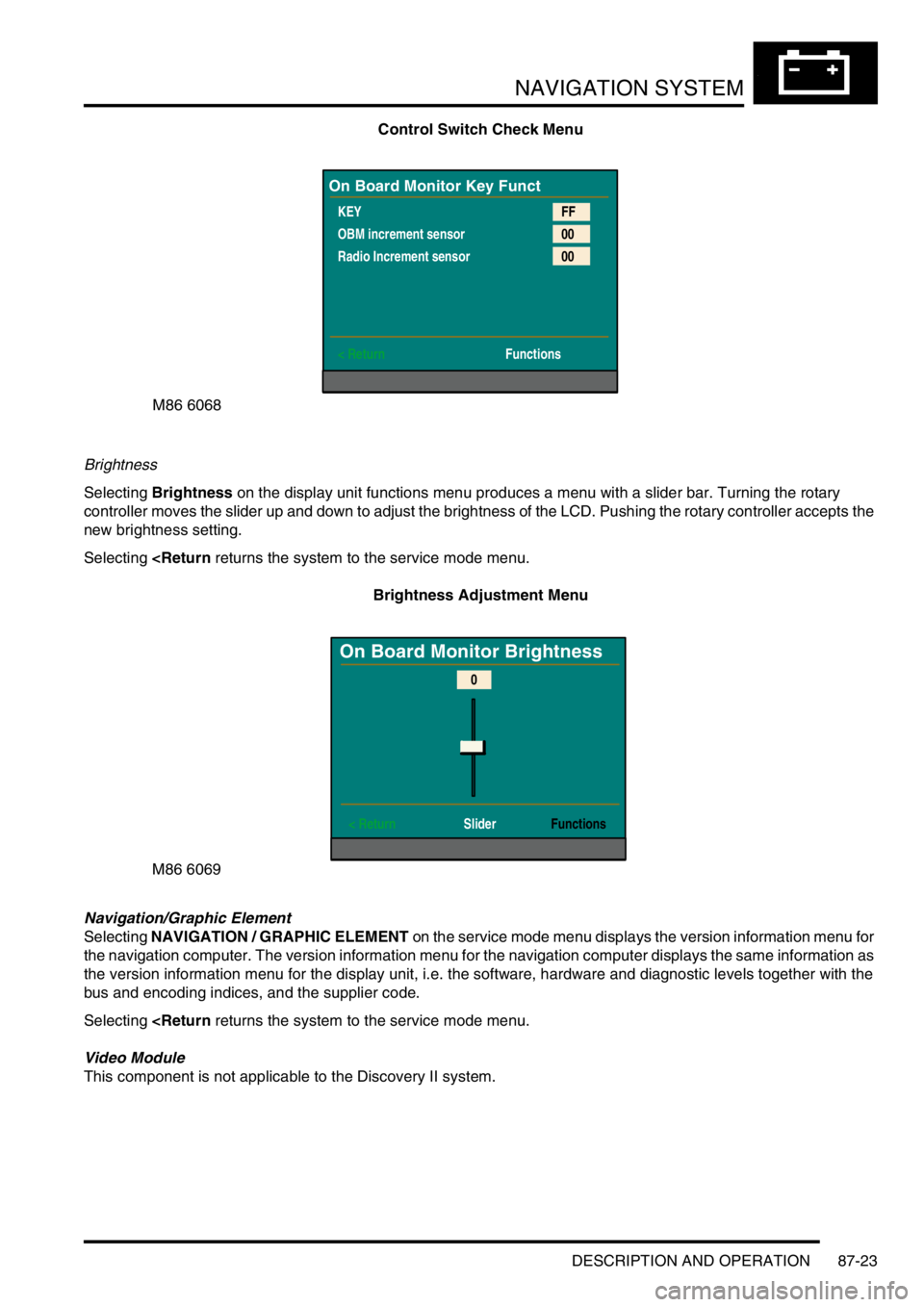
Control Switch Check Menu
Brightness
Selecting Brightness on the display unit functions menu produces a menu with a slider bar. Turning the rotary
controller moves the slider up and down to adjust the brightness of the LCD. Pushing the rotary controller accepts the
new brightness setting.
Selecting
Brightness Adjustment Menu
Navigation/Graphic Element
Selecting NAVIGATION / GRAPHIC ELEMENT on the service mode menu displays the version information menu for
the navigation computer. The version information menu for the navigation computer displays the same information as
the version information menu for the display unit, i.e. the software, hardware and diagnostic levels together with the
bus and encoding indices, and the supplier code.
Selecting
Video Module
This component is not applicable to the Discovery II system.
M86 6068
On Board Monitor Key Funct
KEY
OBM increment sensor
Radio Increment sensor
< ReturnFF
00
00
Functions
M86 6069
On Board Monitor Brightness
< Return SliderFunctions
0