Page 1432 of 1529
HARNESSES
REPAIRS 86-7-27
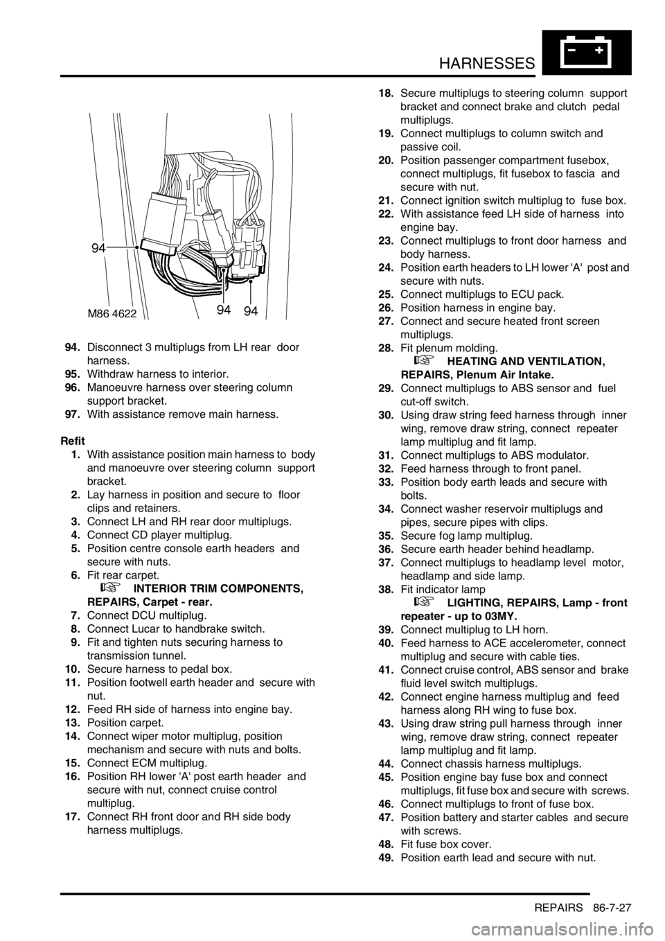
94.Disconnect 3 multiplugs from LH rear door
harness.
95.Withdraw harness to interior.
96.Manoeuvre harness over steering column
support bracket.
97.With assistance remove main harness.
Refit
1.With assistance position main harness to body
and manoeuvre over steering column support
bracket.
2.Lay harness in position and secure to floor
clips and retainers.
3.Connect LH and RH rear door multiplugs.
4.Connect CD player multiplug.
5.Position centre console earth headers and
secure with nuts.
6.Fit rear carpet.
+ INTERIOR TRIM COMPONENTS,
REPAIRS, Carpet - rear.
7.Connect DCU multiplug.
8.Connect Lucar to handbrake switch.
9.Fit and tighten nuts securing harness to
transmission tunnel.
10.Secure harness to pedal box.
11.Position footwell earth header and secure with
nut.
12.Feed RH side of harness into engine bay.
13.Position carpet.
14.Connect wiper motor multiplug, position
mechanism and secure with nuts and bolts.
15.Connect ECM multiplug.
16.Position RH lower 'A' post earth header and
secure with nut, connect cruise control
multiplug.
17.Connect RH front door and RH side body
harness multiplugs. 18.Secure multiplugs to steering column support
bracket and connect brake and clutch pedal
multiplugs.
19.Connect multiplugs to column switch and
passive coil.
20.Position passenger compartment fusebox,
connect multiplugs, fit fusebox to fascia and
secure with nut.
21.Connect ignition switch multiplug to fuse box.
22.With assistance feed LH side of harness into
engine bay.
23.Connect multiplugs to front door harness and
body harness.
24.Position earth headers to LH lower 'A' post and
secure with nuts.
25.Connect multiplugs to ECU pack.
26.Position harness in engine bay.
27.Connect and secure heated front screen
multiplugs.
28.Fit plenum molding.
+ HEATING AND VENTILATION,
REPAIRS, Plenum Air Intake.
29.Connect multiplugs to ABS sensor and fuel
cut-off switch.
30.Using draw string feed harness through inner
wing, remove draw string, connect repeater
lamp multiplug and fit lamp.
31.Connect multiplugs to ABS modulator.
32.Feed harness through to front panel.
33.Position body earth leads and secure with
bolts.
34.Connect washer reservoir multiplugs and
pipes, secure pipes with clips.
35.Secure fog lamp multiplug.
36.Secure earth header behind headlamp.
37.Connect multiplugs to headlamp level motor,
headlamp and side lamp.
38.Fit indicator lamp
+ LIGHTING, REPAIRS, Lamp - front
repeater - up to 03MY.
39.Connect multiplug to LH horn.
40.Feed harness to ACE accelerometer, connect
multiplug and secure with cable ties.
41.Connect cruise control, ABS sensor and brake
fluid level switch multiplugs.
42.Connect engine harness multiplug and feed
harness along RH wing to fuse box.
43.Using draw string pull harness through inner
wing, remove draw string, connect repeater
lamp multiplug and fit lamp.
44.Connect chassis harness multiplugs.
45.Position engine bay fuse box and connect
multiplugs, fit fuse box and secure with screws.
46.Connect multiplugs to front of fuse box.
47.Position battery and starter cables and secure
with screws.
48.Fit fuse box cover.
49.Position earth lead and secure with nut.
Page 1484 of 1529
INSTRUMENTS
DESCRIPTION AND OPERATION 88-1
INS TRUMENTS DESCRIPTION AND OPERAT ION
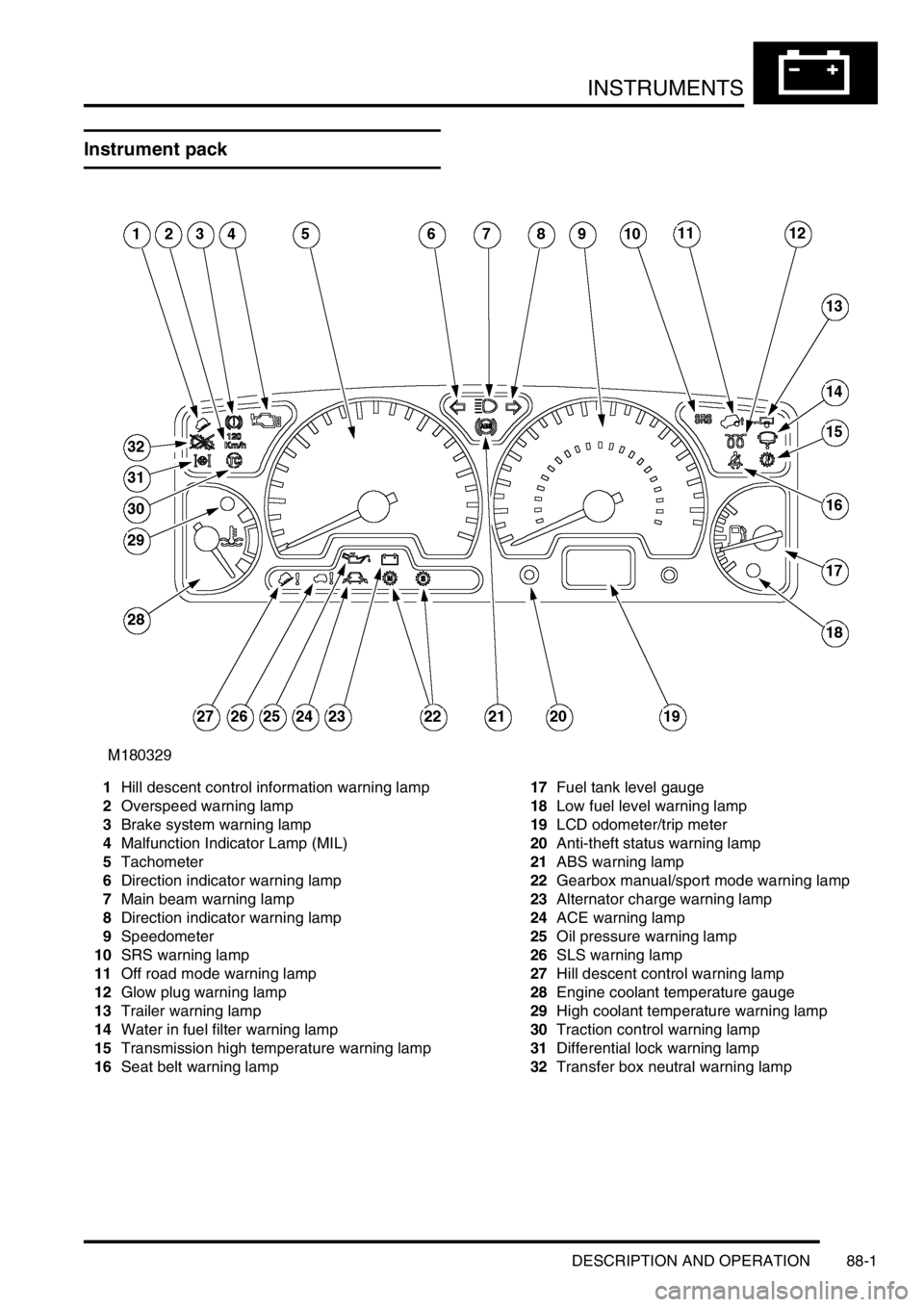
Instrument pack
1Hill descent control information warning lamp
2Overspeed warning lamp
3Brake system warning lamp
4Malfunction Indicator Lamp (MIL)
5Tachometer
6Direction indicator warning lamp
7Main beam warning lamp
8Direction indicator warning lamp
9Speedometer
10SRS warning lamp
11Off road mode warning lamp
12Glow plug warning lamp
13Trailer warning lamp
14Water in fuel filter warning lamp
15Transmission high temperature warning lamp
16Seat belt warning lamp17Fuel tank level gauge
18Low fuel level warning lamp
19LCD odometer/trip meter
20Anti-theft status warning lamp
21ABS warning lamp
22Gearbox manual/sport mode warning lamp
23Alternator charge warning lamp
24ACE warning lamp
25Oil pressure warning lamp
26SLS warning lamp
27Hill descent control warning lamp
28Engine coolant temperature gauge
29High coolant temperature warning lamp
30Traction control warning lamp
31Differential lock warning lamp
32Transfer box neutral warning lamp
Page 1485 of 1529
INSTRUMENTS
88-2 DESCRIPTION AND OPERATION
Instrument component location - Engine
compartment / underneath vehicle
1ECM (diesel models)
2Alternator
3Glow plugs
4Transmission temperature sensor
5Water in fuel filter sensor
6Fuel tank sender unit
7Differential lock switch – vehicles up to 03
model year8Differential lock switches – vehicles from 03
model year (where fitted)
9Parking brake switch
10Brake fluid level switch
11Oil pressure switch
Page 1516 of 1529
INSTRUMENTS
DESCRIPTION AND OPERATION 88-33
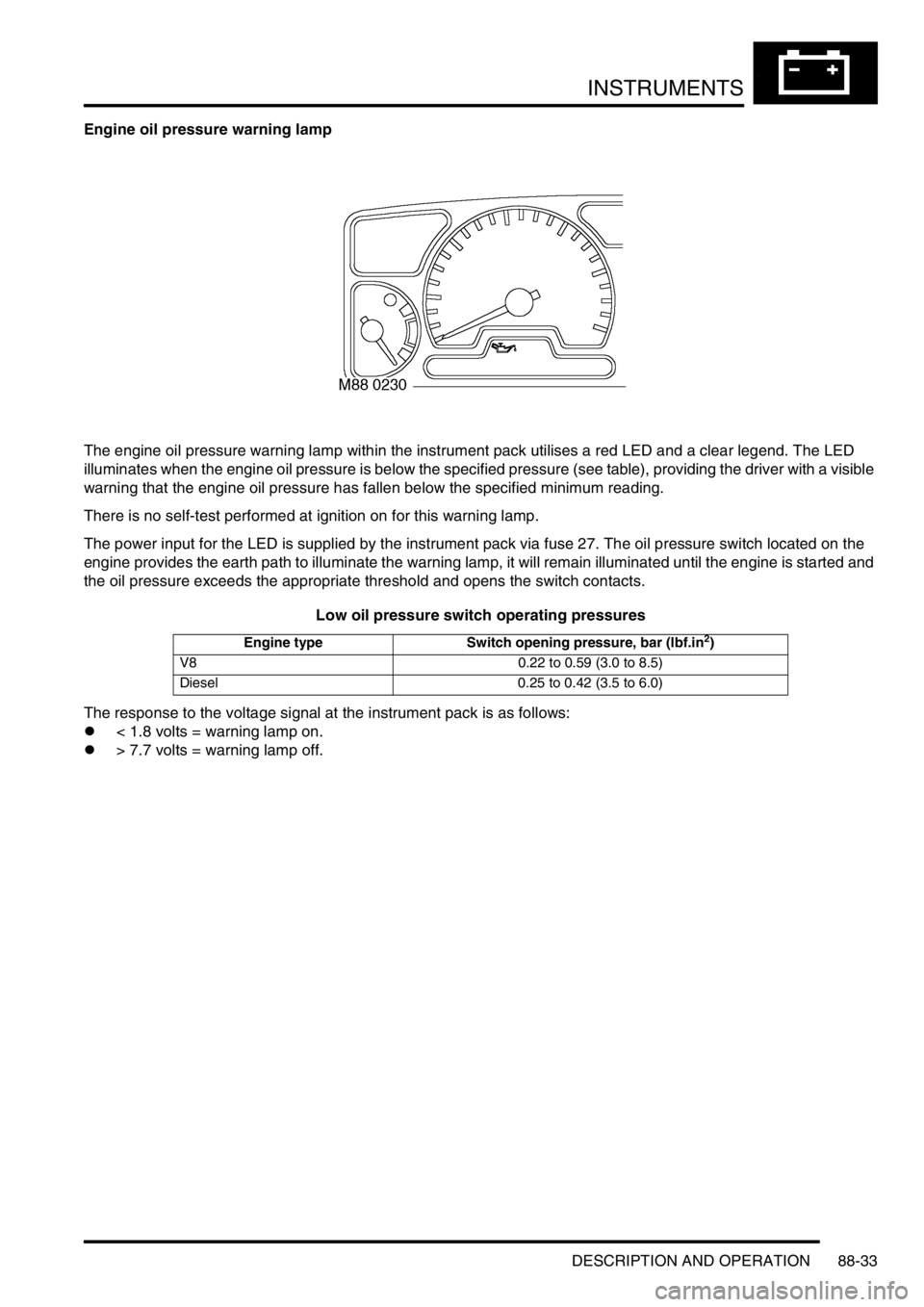
Engine oil pressure warning lamp
The engine oil pressure warning lamp within the instrument pack utilises a red LED and a clear legend. The LED
illuminates when the engine oil pressure is below the specified pressure (see table), providing the driver with a visible
warning that the engine oil pressure has fallen below the specified minimum reading.
There is no self-test performed at ignition on for this warning lamp.
The power input for the LED is supplied by the instrument pack via fuse 27. The oil pressure switch located on the
engine provides the earth path to illuminate the warning lamp, it will remain illuminated until the engine is started and
the oil pressure exceeds the appropriate threshold and opens the switch contacts.
Low oil pressure switch operating pressures
The response to the voltage signal at the instrument pack is as follows:
l< 1.8 volts = warning lamp on.
l> 7.7 volts = warning lamp off.
Engine type Switch opening pressure, bar (lbf.in2)
V8 0.22 to 0.59 (3.0 to 8.5)
Diesel 0.25 to 0.42 (3.5 to 6.0)
Page 1519 of 1529
INSTRUMENTS
88-36 DESCRIPTION AND OPERATION
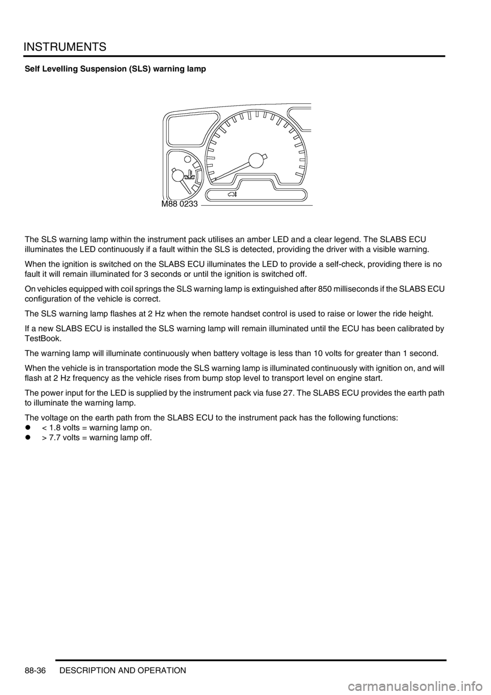
Self Levelling Suspension (SLS) warning lamp
The SLS warning lamp within the instrument pack utilises an amber LED and a clear legend. The SLABS ECU
illuminates the LED continuously if a fault within the SLS is detected, providing the driver with a visible warning.
When the ignition is switched on the SLABS ECU illuminates the LED to provide a self-check, providing there is no
fault it will remain illuminated for 3 seconds or until the ignition is switched off.
On vehicles equipped with coil springs the SLS warning lamp is extinguished after 850 milliseconds if the SLABS ECU
configuration of the vehicle is correct.
The SLS warning lamp flashes at 2 Hz when the remote handset control is used to raise or lower the ride height.
If a new SLABS ECU is installed the SLS warning lamp will remain illuminated until the ECU has been calibrated by
TestBook.
The warning lamp will illuminate continuously when battery voltage is less than 10 volts for greater than 1 second.
When the vehicle is in transportation mode the SLS warning lamp is illuminated continuously with ignition on, and will
flash at 2 Hz frequency as the vehicle rises from bump stop level to transport level on engine start.
The power input for the LED is supplied by the instrument pack via fuse 27. The SLABS ECU provides the earth path
to illuminate the warning lamp.
The voltage on the earth path from the SLABS ECU to the instrument pack has the following functions:
l< 1.8 volts = warning lamp on.
l> 7.7 volts = warning lamp off.
Page 1525 of 1529
INSTRUMENTS
88-42 DESCRIPTION AND OPERATION
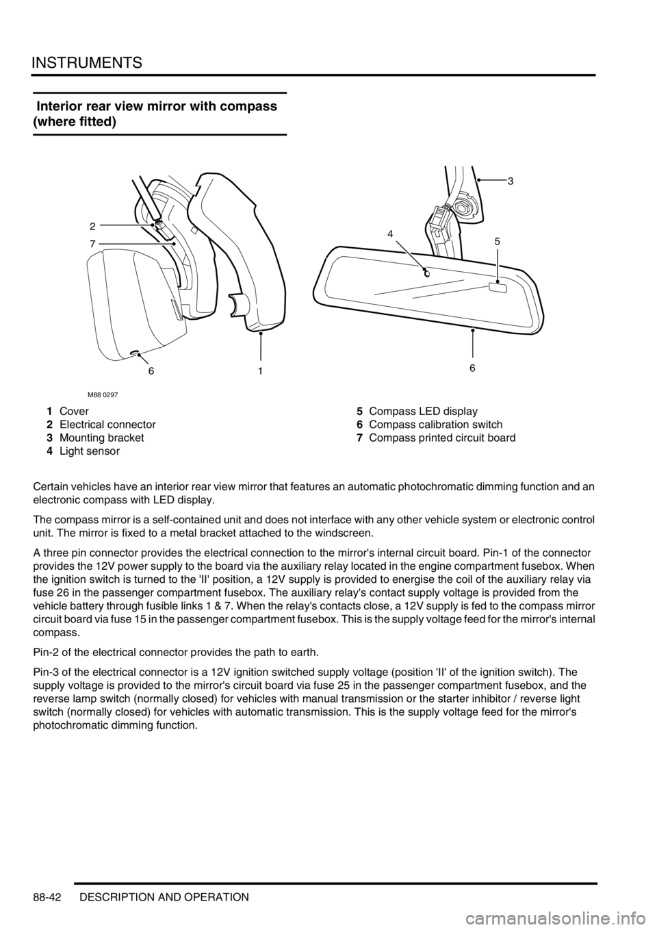
Interior rear view mirror with compass
(where fitted)
1Cover
2Electrical connector
3Mounting bracket
4Light sensor5Compass LED display
6Compass calibration switch
7Compass printed circuit board
Certain vehicles have an interior rear view mirror that features an automatic photochromatic dimming function and an
electronic compass with LED display.
The compass mirror is a self-contained unit and does not interface with any other vehicle system or electronic control
unit. The mirror is fixed to a metal bracket attached to the windscreen.
A three pin connector provides the electrical connection to the mirror's internal circuit board. Pin-1 of the connector
provides the 12V power supply to the board via the auxiliary relay located in the engine compartment fusebox. When
the ignition switch is turned to the 'II' position, a 12V supply is provided to energise the coil of the auxiliary relay via
fuse 26 in the passenger compartment fusebox. The auxiliary relay's contact supply voltage is provided from the
vehicle battery through fusible links 1 & 7. When the relay's contacts close, a 12V supply is fed to the compass mirror
circuit board via fuse 15 in the passenger compartment fusebox. This is the supply voltage feed for the mirror's internal
compass.
Pin-2 of the electrical connector provides the path to earth.
Pin-3 of the electrical connector is a 12V ignition switched supply voltage (position 'II' of the ignition switch). The
supply voltage is provided to the mirror's circuit board via fuse 25 in the passenger compartment fusebox, and the
reverse lamp switch (normally closed) for vehicles with manual transmission or the starter inhibitor / reverse light
switch (normally closed) for vehicles with automatic transmission. This is the supply voltage feed for the mirror's
photochromatic dimming function.
M88 0297
3
2
7
616
45