1999 LAND ROVER DISCOVERY engine oil
[x] Cancel search: engine oilPage 1318 of 1529

BODY CONTROL UNIT
DESCRIPTION AND OPERATION 86-3-31
Gear position indicator illumination
On automatic gearbox models, two variations of illumination for the gear position indicators on the selector lever can
be programmed into the BCU. In option 1, illumination is provided when the ignition is on. In option 2, illumination is
enabled when the ignition is on and the side lamps are off.
Starter relay
The BCU checks the status of the following inputs and internal BCU conditions to determine whether or not to provide
an output to enable the starter relay:
lAutostart inhibit (vehicles with automatic gearbox only).
lSecurity start inhibit (immobilisation check).
lEngine running (link to instrument pack).
lEEPROM locked (internal check).
lIDM and BCU matched.
When the BCU receives a crank signal from the ignition switch, an earth path is completed to the starter relay coil,
provided that the security system has been de-activated. If the ECM has not received a valid unlock/ remobilise signal,
the starter relay will be disengaged and the engine stopped. The BCU also receives an engine running signal from
the instrument pack, so that if the ignition key is turned to the crank position while the engine is running, the starter
motor relay will not be engaged.
If the logic conditions are correct to allow starter operation, the completion of the earth path from the starter relay coil
to the BCU energises the coil and the relay contacts close to supply battery power to the starter motor.
When the ignition switch is released from the crank position, the power supply feed from the ignition switch to the
starter relay coil is interrupted and the relay contacts open to prevent further battery feed to the starter motor.
If a communications link failure is experienced, the BCU will be prevented from detecting the 'engine running'
condition and the BCU will default to assume that the engine is not running.
Cruise control
The Neutral/ Reverse/ Park/ Brake selected output is used by the cruise control system. The BCU checks for the
following inputs:
lIgnition on.
lGearbox state.
lBrake switch activated.
For vehicles with manual transmission, Neutral/ Reverse/ Park/ Brake selected output is on if the ignition is on and
brake switch activated is on. Otherwise, the Neutral/ Reverse/ Park/ Brake selected output is off.
For vehicles with automatic transmission, the Neutral/ Reverse/ Park/ Brake selected output is on if the ignition is on
and brake switch activated is on, or if the ignition is on and 'gearbox state' is in Neutral, Park or Reverse. Otherwise
Neutral/ Reverse/ Park/ Brake selected output is off.
Shift interlock (where fitted)
On automatic gearbox models, the BCU and IDM combine to operate a shift interlock solenoid, so that the gear
selector lever can only be moved when certain logical conditions have been satisfied. Operation of the interlock may
be affected, if the battery becomes discharged.
+ AUTOMATIC GEARBOX - ZF4HP22 - 24, DESCRIPTION AND OPERATION, Description.
When the gear selector lever is in the Park position and the ignition is off, an interlock solenoid is de-energised, locking
the gear selector lever in the Park position.
The gear selector lever can only be moved from the Park position when the ignition is switched on and the brake pedal
is depressed. When these conditions are satisfied, the brake pedal switch signal is received by the BCU which then
signals the IDM to energise the interlock relay. When the interlock relay is energised, the interlock solenoid is
operated, unlocking the gear selector lever.
When the brake pedal is released, the feed to the BCU is removed and the shift interlock solenoid is de-energised.
The locking mechanism controlled by the solenoid will lock the gear selector lever once it is returned to the Park
position.
Page 1336 of 1529
ALARM SYSTEM AND HORN
DESCRIPTION AND OPERATION 86-4-13
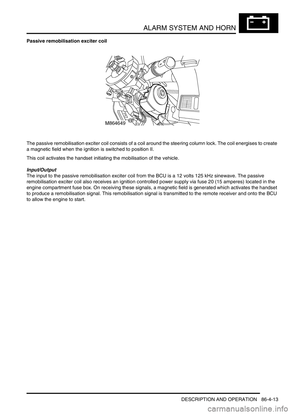
Passive remobilisation exciter coil
The passive remobilisation exciter coil consists of a coil around the steering column lock. The coil energises to create
a magnetic field when the ignition is switched to position II.
This coil activates the handset initiating the mobilisation of the vehicle.
Input/Output
The input to the passive remobilisation exciter coil from the BCU is a 12 volts 125 kHz sinewave. The passive
remobilisation exciter coil also receives an ignition controlled power supply via fuse 20 (15 amperes) located in the
engine compartment fuse box. On receiving these signals, a magnetic field is generated which activates the handset
to produce a remobilisation signal. This remobilisation signal is transmitted to the remote receiver and onto the BCU
to allow the engine to start.
Page 1344 of 1529

ALARM SYSTEM AND HORN
DESCRIPTION AND OPERATION 86-4-21
Passive immobilisation
Passive immobilisation prevents the vehicle from being started unless the authorised key is used to start the vehicle.
There are only two configurations for passive immobilisation:
lpassive immobilisation not active
lpassive immobilisation active
When the ignition is switched off, the vehicle remains mobilised for up to a maximum of 5 minutes. If however the
driver's door is opened, after 2 minutes 30 seconds, the vehicle remains in a mobilised state for a further 30 seconds.
When the timer in the BCU has expired, the vehicle is immobilised.
Once the ignition is switched on, the BCU transmits a coded signal to the ECM. If the coded signal does not
correspond to the programmed code in the ECM, the ECM is inhibited and the BCU inhibits the starting circuit.
In order for passive immobilisation to occur, the following conditions must be met:
lDriver's door closed.
lFuel cut-off switch not tripped.
lKey not inserted in ignition.
Passive remobilisation
Whenever the vehicle is immobilised, passive remobilisation of the engine occurs when the ignition is switched on,
allowing the vehicle to be started.
There are three configurations for passive remobilisation:
lPassive immobilisation not active.
lPassive immobilisation active.
lEKA with super locking on receiving good passive remobilisation exciter coil signal.
The BCU controls the passive remobilisation exciter coil (located around the ignition barrel) to generate a magnetic
field which causes the handset to transmit a remobilisation signal. The BCU receives the signal and allows the vehicle
to be started. If a valid signal from the handset is not received within one minute of the ignition being switched to
position II, the BCU stops the passive coil from generating the magnetic field.
Emergency key access
If the handset fails to operate, the engine can be remobilised by using the key to enter a unique four digit Emergency
Key Access (EKA) code.
There are three configurations for emergency key access:
lEKA not active (no immobiliser fitted).
lEKA active.
lEKA with super locking on receiving good passive remobilisation exciter coil signal.
Page 1413 of 1529
HARNESSES
86-7-8 REPAIRS
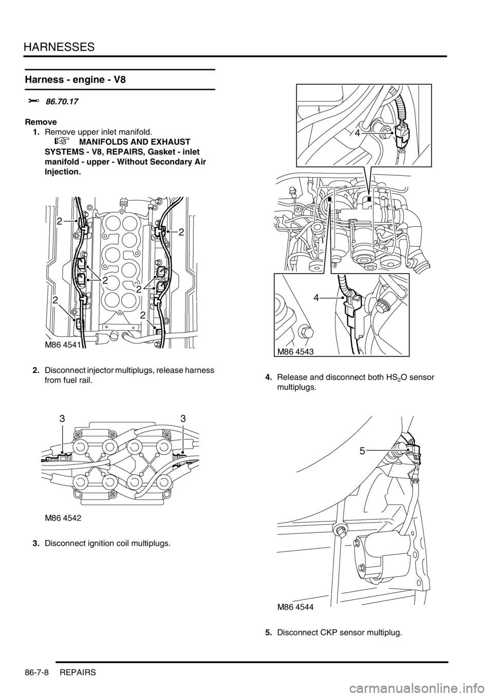
Harness - engine - V8
$% 86.70.17
Remove
1.Remove upper inlet manifold.
+ MANIFOLDS AND EXHAUST
SYSTEMS - V8, REPAIRS, Gasket - inlet
manifold - upper - Without Secondary Air
Injection.
2.Disconnect injector multiplugs, release harness
from fuel rail.
3.Disconnect ignition coil multiplugs.4.Release and disconnect both HS
2O sensor
multiplugs.
5.Disconnect CKP sensor multiplug.
Page 1416 of 1529
HARNESSES
REPAIRS 86-7-11
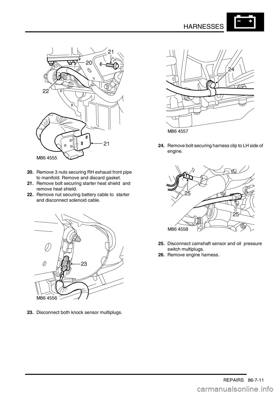
20.Remove 3 nuts securing RH exhaust front pipe
to manifold. Remove and discard gasket.
21.Remove bolt securing starter heat shield and
remove heat shield.
22.Remove nut securing battery cable to starter
and disconnect solenoid cable.
23.Disconnect both knock sensor multiplugs.24.Remove bolt securing harness clip to LH side of
engine.
25.Disconnect camshaft sensor and oil pressure
switch multiplugs.
26.Remove engine harness.
Page 1417 of 1529
HARNESSES
86-7-12 REPAIRS
Refit
1.Position engine harness around engine.
2.Connect oil pressure switch and camshaft
sensor multiplugs.
3.Fit and tighten bolt securing harness to LH side
of engine.
4.Connect both knock sensor multiplugs.
5.Connect battery cable and solenoid cable to
starter motor.
6.Position starter heat shield and secure with
bolt.
7.Clean exhaust flange mating faces, using a
new gasket align exhaust fit nuts and tighten to
60 Nm (44 lbf.ft).
8.Remove stand(s) and lower vehicle.
9.Position harness into footwell and secure
grommet.
10.Connect ECM multiplugs.
11.Position toe board and secure with trim fixings.
12.Connect engine harness to main harness
multiplug and secure earth lead.
13.Connect EVAP solenoid multiplug.
14.Connect both fuse box multiplugs.
15.Position starter lead to fuse box and secure
screw.
16.Fit fuse box cover.
17.Position battery positive lead to battery and
secure nut.
18.Secure harness to coolant rail.
19.Position alternator cables and tighten terminal
B+ to 18 Nm (13 lbf.ft) and terminal D+ to 5 Nm
(3.7 lbf.ft)
20.Connect coolant temperature sensor multiplug.
21.Connect A/C compressor multiplug.
22.Secure harness clip to rear of LH cylinder head.
23.Connect CKP sensor multiplug.
24.Secure injector harness and connect injector
multiplugs.
25.Connect coil multiplugs.
26.Connect and secure HS
2O sensor multiplug
27.Fit upper inlet manifold.
+ MANIFOLDS AND EXHAUST
SYSTEMS - V8, REPAIRS, Gasket - inlet
manifold - upper - Without Secondary Air
Injection.
28.Connect battery earth lead.
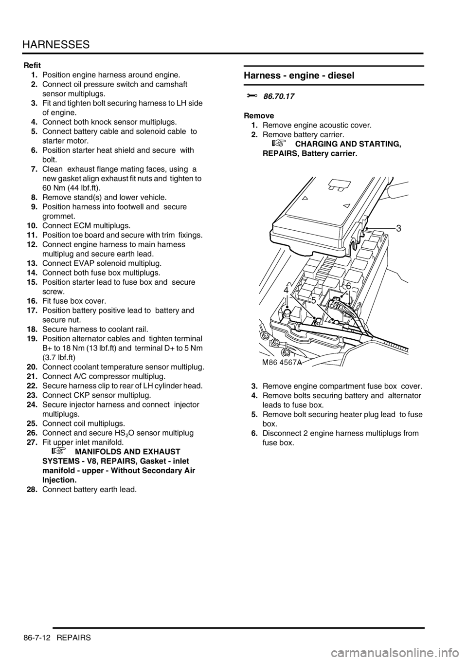
Harness - engine - diesel
$% 86.70.17
Remove
1.Remove engine acoustic cover.
2.Remove battery carrier.
+ CHARGING AND STARTING,
REPAIRS, Battery carrier.
3.Remove engine compartment fuse box cover.
4.Remove bolts securing battery and alternator
leads to fuse box.
5.Remove bolt securing heater plug lead to fuse
box.
6.Disconnect 2 engine harness multiplugs from
fuse box.
Page 1418 of 1529
HARNESSES
REPAIRS 86-7-13
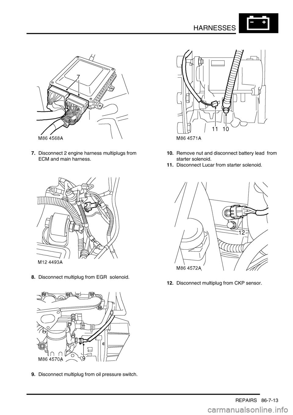
7.Disconnect 2 engine harness multiplugs from
ECM and main harness.
8.Disconnect multiplug from EGR solenoid.
9.Disconnect multiplug from oil pressure switch. 10.Remove nut and disconnect battery lead from
starter solenoid.
11.Disconnect Lucar from starter solenoid.
12.Disconnect multiplug from CKP sensor.
Page 1420 of 1529
HARNESSES
REPAIRS 86-7-15
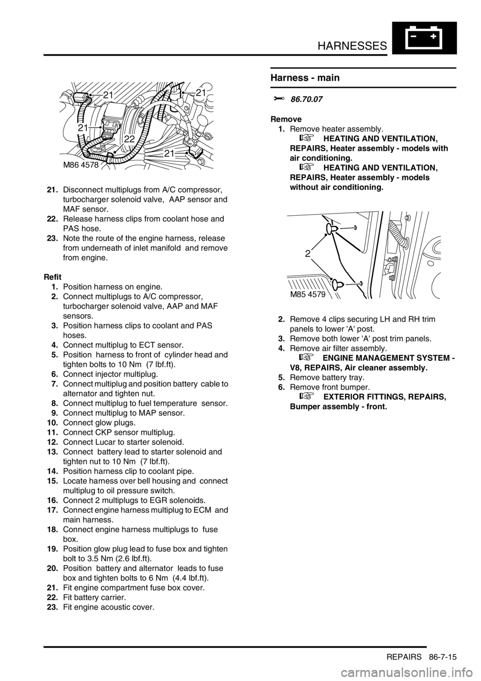
21.Disconnect multiplugs from A/C compressor,
turbocharger solenoid valve, AAP sensor and
MAF sensor.
22.Release harness clips from coolant hose and
PAS hose.
23.Note the route of the engine harness, release
from underneath of inlet manifold and remove
from engine.
Refit
1.Position harness on engine.
2.Connect multiplugs to A/C compressor,
turbocharger solenoid valve, AAP and MAF
sensors.
3.Position harness clips to coolant and PAS
hoses.
4.Connect multiplug to ECT sensor.
5.Position harness to front of cylinder head and
tighten bolts to 10 Nm (7 lbf.ft).
6.Connect injector multiplug.
7.Connect multiplug and position battery cable to
alternator and tighten nut.
8.Connect multiplug to fuel temperature sensor.
9.Connect multiplug to MAP sensor.
10.Connect glow plugs.
11.Connect CKP sensor multiplug.
12.Connect Lucar to starter solenoid.
13.Connect battery lead to starter solenoid and
tighten nut to 10 Nm (7 lbf.ft).
14.Position harness clip to coolant pipe.
15.Locate harness over bell housing and connect
multiplug to oil pressure switch.
16.Connect 2 multiplugs to EGR solenoids.
17.Connect engine harness multiplug to ECM and
main harness.
18.Connect engine harness multiplugs to fuse
box.
19.Position glow plug lead to fuse box and tighten
bolt to 3.5 Nm (2.6 lbf.ft).
20.Position battery and alternator leads to fuse
box and tighten bolts to 6 Nm (4.4 lbf.ft).
21.Fit engine compartment fuse box cover.
22.Fit battery carrier.
23.Fit engine acoustic cover.
Harness - main
$% 86.70.07
Remove
1.Remove heater assembly.
+ HEATING AND VENTILATION,
REPAIRS, Heater assembly - models with
air conditioning.
+ HEATING AND VENTILATION,
REPAIRS, Heater assembly - models
without air conditioning.
2.Remove 4 clips securing LH and RH trim
panels to lower 'A' post.
3.Remove both lower 'A' post trim panels.
4.Remove air filter assembly.
+ ENGINE MANAGEMENT SYSTEM -
V8, REPAIRS, Air cleaner assembly.
5.Remove battery tray.
6.Remove front bumper.
+ EXTERIOR FITTINGS, REPAIRS,
Bumper assembly - front.