1999 LAND ROVER DISCOVERY engine oil
[x] Cancel search: engine oilPage 763 of 1529

FRONT SUSPENSION
60-18 DESCRIPTION AND OPERATION
ACE Electronic control unit (ECU)
1Body Control Unit (Ref. only)
2Bracket3ACE Electronic control unit
4Attachment nuts 3 off
The ACE ECU is mounted on a bracket behind the passenger glove box and is identified from the other ECU's by its
single electrical harness connector. The single 36 pin connector is located on the lower face of the ECU and mates
with a connector from the main harness. The connector supplies power, ground, signal and sensor information to/from
the ECU for control of the ACE system.
The ACE ECU receives a battery power supply from fuse 15 in the engine compartment fusebox via the ACE relay,
also located in the engine compartment fusebox. The ECU provides an earth path for the relay coil, energising the
coil and supplying power to the ECU.
An ignition on signal is supplied from the ignition switch via fuse 29 in the passenger compartment fusebox. The
ignition on signal provides an input to the ECU which tells the ECU that ignition has been selected on and initiates a
250 ms start time. The start time is used to prevent functions operating when software routines are being initialised.
The ignition on signal, when removed, tells the ECU that the ignition is off. The ECU will remain powered for thirty
seconds after the ignition is turned off. The thirty second period allows the ECU to store values and fault flags in the
memory. These values are read by the ECU when the next ignition on signal is received.
An engine speed signal is transmitted to the ECU from the Engine Control Module (ECM) as a pulsed digital signal.
The engine speed signal is used by the ACE ECU to detect that the engine is running and hydraulic pressure for ACE
system operation is available.
A road speed signal is transmitted to the ACE ECU as a pulsed digital signal from the Self-levelling/Anti-lock Braking
System (SLABS) ECU. The road speed signal is used by the ACE ECU for on and off-road roll compensation.
When reverse gear is selected, an input is received from the reverse lamp switch. When the ACE ECU detects that
reverse gear has been selected, the ACE system reverts to a 'locked bars' condition until reverse gear is disengaged.
The diagnostic connection allows diagnostic interrogation of the ACE ECU. The diagnostic socket allows diagnostic
equipment to be connected to interrogate the ACE ECU for fault codes.
Page 863 of 1529

BRAKES
70-10 DESCRIPTION AND OPERATION
Vacuum pump (diesel models only)
1Alternator
2Vacuum pump
3Brake servo assembly vacuum connection4Oil feed pipe
5Oil drain pipe
As the diesel engine air inlet system does not produce sufficient depression to operate the brake servo assembly, an
engine driven vacuum pump is installed.
The vacuum pump is integrated with the engine alternator and driven by the auxiliary drive belt. The pump is a rotary
vane type, lubricated and cooled by engine oil supplied through a pipe connected to the engine block and returned
through a pipe connected to the engine oil sump. Air extracted from the brake servo assembly is vented into the oil
sump with returning lubricating oil.
Page 897 of 1529

BRAKES
70-44 REPAIRS
Refit
1.Clean mating faces of alternator and vacuum
pump.
2.Fit vacuum pump to alternator and tighten
bolts to 8 Nm (6 lbf.ft).
3.Position alternator to engine and connect
multiplug.
4.Connect vacuum hose and oil drain hose to
vacuum pump and secure clips.
5.With assistance align alternator to mounting
bracket and fit but do not tighten bolt.
6.Fit bolt securing support stay to alternator and
tighten to 25 Nm (18 lbf.ft) .
7.Tighten bolt securing alternator to mounting
bracket to 45 Nm (33 lbf.ft).
8.Using new 'O' ring, connect oil supply pipe to
cylinder head and tighten to 10 Nm (7 lbf.ft).
9.Connect lead to alternator and tighten nut to 6
Nm (4.4 lbf.ft).
10.Fit auxiliary drive belt tensioner and tighten bolt
to 50 Nm (37 lbf.ft).
11.Fit auxiliary drive belt.
+ CHARGING AND STARTING,
REPAIRS, Belt - auxiliary drive.
Page 1001 of 1529

SEATS
76-5-4 DESCRIPTION AND OPERATION
Description - electric seats
General
All markets use the same electric seat system. Electically operated lumbar support is optional. The system consists
of an electrical sub-system and a mechanical sub-system.
The electrical sub-system consists of the following components:
lBCU.
lSeat power relays.
lSeat switch packs.
lSeat fore/ aft motors.
lSeat cushion front up/ down motors.
lSeat cushion rear up/ down motors.
lSeat squab motor.
lLumbar pump.
lLumbar deflate solenoid.
The mechanical sub-system consist of the following components:
lGear wheels.
lRack and pinion assemblies.
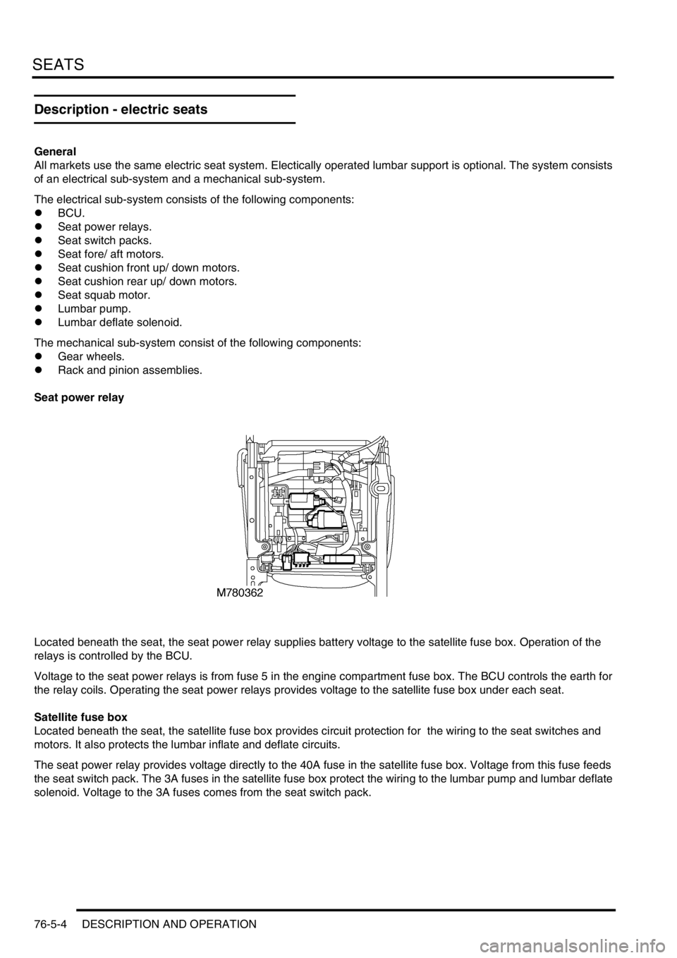
Seat power relay
Located beneath the seat, the seat power relay supplies battery voltage to the satellite fuse box. Operation of the
relays is controlled by the BCU.
Voltage to the seat power relays is from fuse 5 in the engine compartment fuse box. The BCU controls the earth for
the relay coils. Operating the seat power relays provides voltage to the satellite fuse box under each seat.
Satellite fuse box
Located beneath the seat, the satellite fuse box provides circuit protection for the wiring to the seat switches and
motors. It also protects the lumbar inflate and deflate circuits.
The seat power relay provides voltage directly to the 40A fuse in the satellite fuse box. Voltage from this fuse feeds
the seat switch pack. The 3A fuses in the satellite fuse box protect the wiring to the lumbar pump and lumbar deflate
solenoid. Voltage to the 3A fuses comes from the seat switch pack.
Page 1218 of 1529

AIR CONDITIONING
REPAIRS 82-29
REPAIRS
Compressor - diesel
$% 82.10.20
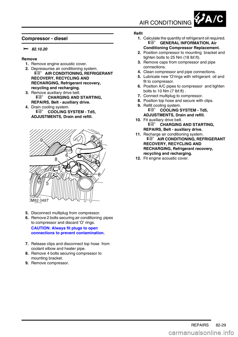
Remove
1.Remove engine acoustic cover.
2.Depressurise air conditioning system.
+ AIR CONDITIONING, REFRIGERANT
RECOVERY, RECYCLING AND
RECHARGING, Refrigerant recovery,
recycling and recharging.
3.Remove auxiliary drive belt.
+ CHARGING AND STARTING,
REPAIRS, Belt - auxiliary drive.
4.Drain cooling system.
+ COOLING SYSTEM - Td5,
ADJUSTMENTS, Drain and refill.
5.Disconnect multiplug from compressor.
6.Remove 2 bolts securing air conditioning pipes
to compressor and discard 'O' rings.
CAUTION: Always fit plugs to open
connections to prevent contamination.
7.Release clips and disconnect top hose from
coolant elbow and heater pipe.
8.Remove 4 bolts securing compressor to
mounting bracket.
9.Remove compressor.Refit
1.Calculate the quantity of refrigerant oil required.
+ GENERAL INFORMATION, Air
Conditioning Compressor Replacement.
2.Position compressor to mounting bracket and
tighten bolts to 25 Nm (18 lbf.ft).
3.Remove caps from compressor and pipe
connections.
4.Clean compressor and pipe connections.
5.Lubricate new 'O'rings with refrigerant oil and
fit to compressor.
6.Position A/C pipes to compressor and tighten
bolts to 10 Nm (7 lbf.ft) .
7.Connect multiplug to compressor.
8.Position top hose and secure with clips.
9.Refill cooling system.
+ COOLING SYSTEM - Td5,
ADJUSTMENTS, Drain and refill.
10.Fit auxiliary drive belt.
+ CHARGING AND STARTING,
REPAIRS, Belt - auxiliary drive.
11.Recharge air conditioning system.
+ AIR CONDITIONING, REFRIGERANT
RECOVERY, RECYCLING AND
RECHARGING, Refrigerant recovery,
recycling and recharging.
12.Fit engine acoustic cover.
Page 1243 of 1529

WIPERS AND WASHERS
84-8 DESCRIPTION AND OPERATION
Description
General
All markets have a common wiper system with headlamp powerwash as an option.
The wipers system comprises two front wipers and one rear wiper which are powered by electric motors. A washer
reservoir is located in the front left hand wheel arch and is fitted with two electric pumps. Each pump supplies washer
fluid to either the front or rear screens. On certain models, a third pump can be fitted to operate a headlamp power
wash function. Operation of the front and rear wipers and washers is controlled by the driver using switches located
on a steering column stalk and push button switches on the fascia.
Control of the wipers and washers is achieved by the following components:
lBCU.
lIDM.
lFront wiper relay.
lFront wash/ wipe switch.
lVariable delay switch.
lFront wiper motor assembly.
lFront washer pump motor.
lRear wiper relay.
lRear wiper switch.
lRear washer switch.
lRear wiper motor.
lRear washer pump motor.
Both the Body Control Unit (BCU) and the Intelligent Driver Module (IDM) control the wiper system. The BCU controls
the time delay function of the wiper system and is located below and behind the passenger glovebox. During engine
cranking the BCU prevents wiper functions. Two relays are located in the passenger compartment fusebox. The
relays control the delay operation of the front and rear wipers. The relays are an integral part of the fusebox and
cannot be renewed separately.
Power for the wiper system is supplied by the IDM, which is integral with the passenger fusebox and cannot be
renewed as a component. A serial communication link allows communication between the IDM and the BCU.
The system has diagnostic capabilities through TestBook.
Front wipers
The two front windscreen wipers are operated by a linkage assembly and an electric motor located under the plenum
grill below the windscreen. The linkage and motor assembly is handed for left and right hand drive vehicles. The motor
is an integral part of the linkage and cannot be replaced separately.
The linkage comprises a pressed steel mounting plate which provides for the attachment of a wheel box at each end.
The mounting plate is secured to the bulkhead with flanged nuts which attach to a stud plate located behind the
bulkhead. A link arm is attached to each wheel box by a short link and secured with circlips. The link arm has an
attachment hole centrally located along its length for the electric motor drive link.
The electric motor is mounted in a recess in the bulkhead below a sealed cover plate. The drive spindle of the motor
protrudes through the cover plate and is fitted with a link. The link is attached to a tapered spline on the motor spindle
and is secured with a lock washer and nut. The opposite end of the link is attached to the central attachment point on
the link arm and secured with a circlip.
Each wheel box has a taper splined shaft which allows for the attachment of the wiper arm which is secured with a
washer and nut. The shaft of each wheel box is passed through a rubber sealed aperture in the plenum. The wiper
arm attachment to the splined shaft has a pivot to which the remainder of the arm is attached. The two parts of the
arm are connected by a spring which controls the pressure of the blade on the screen to a predetermined amount.
The wiper blades are attached to the wiper arms with a clips that allow the blade to pivot. Each wiper blade comprises
a number of levers and yokes to which the rubber wiper is attached. The levers and yokes ensure that the pressure
applied by the arm spring is distributed evenly along the full length of the blade. The rubber wiper is held in the yokes
by a pair of stainless steel strips which also contribute to the even distribution of spring pressure along the blade. The
driver's side wiper blade is fitted with an aerofoil which presses the blade onto the screen at high speed. This prevents
the blade from lifting off the screen and maintains the wiping performance.
Page 1251 of 1529

WIPERS AND WASHERS
84-16 DESCRIPTION AND OPERATION
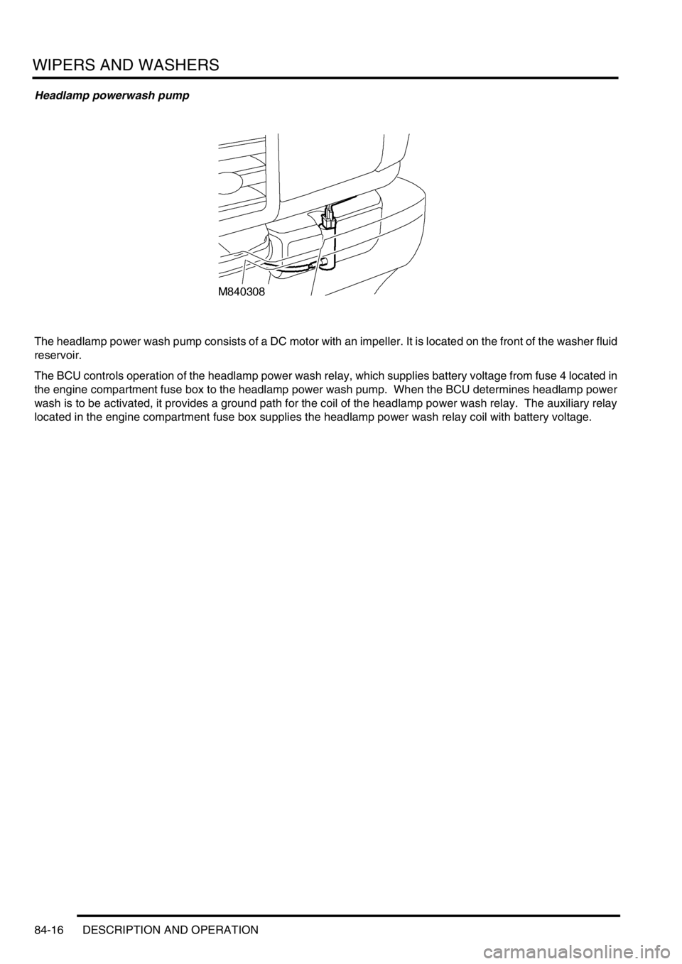
Headlamp powerwash pump
The headlamp power wash pump consists of a DC motor with an impeller. It is located on the front of the washer fluid
reservoir.
The BCU controls operation of the headlamp power wash relay, which supplies battery voltage from fuse 4 located in
the engine compartment fuse box to the headlamp power wash pump. When the BCU determines headlamp power
wash is to be activated, it provides a ground path for the coil of the headlamp power wash relay. The auxiliary relay
located in the engine compartment fuse box supplies the headlamp power wash relay coil with battery voltage.
Page 1267 of 1529

CHARGING AND STARTING
86-1-2 REPAIRS
Refit
1.Clean mating faces of alternator and vacuum
pump.
2.Fit vacuum pump to alternator and tighten
bolts to 8 Nm (6 lbf.ft).
3.Position alternator to engine and connect
multiplug.
4.Connect vacuum hose and oil drain hose to
vacuum pump and secure clips.
5.With assistance align alternator to mounting
bracket and fit but do not tighten bolt.
6.Fit bolt securing support stay to alternator and
tighten to 25 Nm (18 lbf.ft) .
7.Tighten bolt securing alternator to mounting
bracket to 45 Nm (33 lbf.ft).
8.Using new 'O' ring, connect oil supply pipe to
cylinder head and tighten to 10 Nm (7 lbf.ft).
9.Connect lead to alternator and tighten nut to 6
Nm (4.4 lbf.ft).
10.Fit auxiliary drive belt tensioner and tighten bolt
to 50 Nm (37 lbf.ft).
11.Fit auxiliary drive belt.
+ CHARGING AND STARTING,
REPAIRS, Belt - auxiliary drive.