Page 741 of 1529

STEERING
57-48 REPAIRS
Ball joint - track rod
$% 57.55.07
Remove
1.Raise front of vehicle.
WARNING: Do not work on or under a
vehicle supported only by a jack. Always
support the vehicle on safety stands.
2.Remove LH front road wheel.
3.Loosen adjuster clamp bolts.
4.Remove nut securing track rod ball joint to
steering knuckle.
5.Using tool LRT-57-036 break taper joint and
release track rod.
CAUTION: Before disconnecting any part of
the steering linkage, ensure the road wheels
are positioned straight ahead and the
steering wheel is prevented from turning.
Unrestricted turning of the steering wheel
will damage the SRS rotary coupler.
6.Unscrew ball joint and adjuster.
7.Remove clamps from adjuster and track rod. Refit
1.Clean adjuster, clamps and track rod.
2.Fit clamps to track rod and adjuster. Screw in
adjuster and ball joint.
3.Clean ball joint taper and taper seat.
4.Adjust length of track rod so that ball joint taper
is centralised in steering knuckle.
5.Fit track rod to steering knuckle and tighten nut
to 80 Nm (59 lbf.in).
6.Fit road wheel and tighten nuts to 140 Nm (103
lbf.ft).
7.Remove stand(s) and lower vehicle.
8.Check and, if necessary, adjust wheel
alignment.
+ STEERING, ADJUSTMENTS, Wheel
alignment - front.
9.After check/adjustment of wheel alignment,
ensure track rod adjuster clamp bolts are
tightened. Tighten M8 bolts to 22 Nm (16 lbf.ft)
and M10 bolts to 33 Nm (24 lbf.ft).
Page 949 of 1529

EXTERIOR FITTINGS
76-2-2 REPAIRS
8.Remove 8 bolts securing wing to body and
remove wing.
Refit
1.Position wing to body.
2.Connect side repeater lamp to multiplug and fit
to wing.
3.Position wing to body, align wing to bonnet and
front door so that the correct gaps are achieved
and tighten bolts to 17 Nm (13 lbf.ft).
4.Check alignment of wing to bonnet and front
door. If necessary, adjust wing to achieve
correct gaps.
5.Fit and tighten nut securing wing to bracket on
sill finisher to 17 Nm (13 lbf.ft).
6.Fit and tighten screw securing wing to
headlamp surround panel.
7.Fit and tighten bolt securing front of wing to
bracket on body to 17 Nm (13 lbf.ft).
8.Fit wheel arch liner extension to bumper and
secure with screws.
9.Fit front wheel arch liner.
+ EXTERIOR FITTINGS, REPAIRS,
Liner - wheel arch - front.
10.Fit front repeater lamp.
+ LIGHTING, REPAIRS, Lamp - front
repeater - up to 03MY.
Wing - front - from 03MY
$% 76.10.24
Remove
1.Remove the headlamp assembly.
+ LIGHTING, REPAIRS, Headlamp -
from 03MY.
2.Remove the front wheel arch liner.
+ EXTERIOR FITTINGS, REPAIRS,
Liner - wheel arch - front.
3.Remove screw securing wheel arch liner
extension panel to the inner wing.
4.Remove 6 screws securing wheel arch liner
extension panel to the front bumper and
remove the extension panel.
5.Release side repeater lamp from front wing,
disconnect the multiplug and remove the lamp.
Page 951 of 1529

EXTERIOR FITTINGS
76-2-4 REPAIRS
Refit
1.Clean front wing body mounting brackets.
2.Fit and secure the front wheel arch finisher to
the front wing.
3.Position lower support bracket to the front wing,
fit nut and tighten to 8 Nm (6 lbf.ft).
4.Position front wing to body, fit bracket and bolts
but do not tighten at this stage.
5.Check and adjust alignment of the front wing to
the bonnet and door.
6.Tighten the front wing retaining bolts to 8 Nm (6
lbf.ft).
7.Fit bonnet sealing rubber to the front wing
flange.
8.Fit bolt securing lower support bracket to the
body and tighten to 8 Nm (6 lbf.ft).
9.Fit nut securing sill finisher to the front wing
lower support bracket and tighten to 8 Nm (6
lbf.ft).
10.Fit bolt securing front wing to the front support
bracket and tighten to 8 Nm (6 lbf.ft).
11.Fit side repeater lamp to the front wing and
connect the multiplug.
12.Fit front wheel arch liner extension panel to the
front bumper and secure with screws.
13.Fit and tighten screw securing front wheel arch
liner extension panel to the inner wing.
14.Fit the front wheel arch liner.
+ EXTERIOR FITTINGS, REPAIRS,
Liner - wheel arch - front.
15.Fit the headlamp assembly.
+ LIGHTING, REPAIRS, Headlamp -
from 03MY.
Rear folding step
$% 76.10.41
Remove
1.Remove 2 bolts securing step and damper
assembly to chassis.
2.Remove step and damper assembly.
3.Remove 2 patch lock nuts securing damper to
step and discard nuts.
4.Remove damper from step.
Refit
1.Fit damper to step and secure with new patch
lock nuts. Tighten nuts to 17 Nm (13 lbf.ft).
2.Position step and damper assembly to chassis
and secure with bolts. Tighten bolts to 45 Nm
(33 lbf.ft).
Page 1049 of 1529

SUNROOF
76-6-18 REPAIRS
Motor - sunroof
$% 76.84.07
This procedure is applicable to the motor of both
sunroofs.
Remove
1.Gain access to the sunroof motor:
lFor front sunroof motor, remove front
stowage pocket.
+ INTERIOR TRIM COMPONENTS,
REPAIRS, Stowage pocket - front.
lFor rear sunroof motor, remove headlining.
+ INTERIOR TRIM COMPONENTS,
REPAIRS, Headlining.
CAUTION: The sunroof must be fully closed
before removing the sunroof motor.
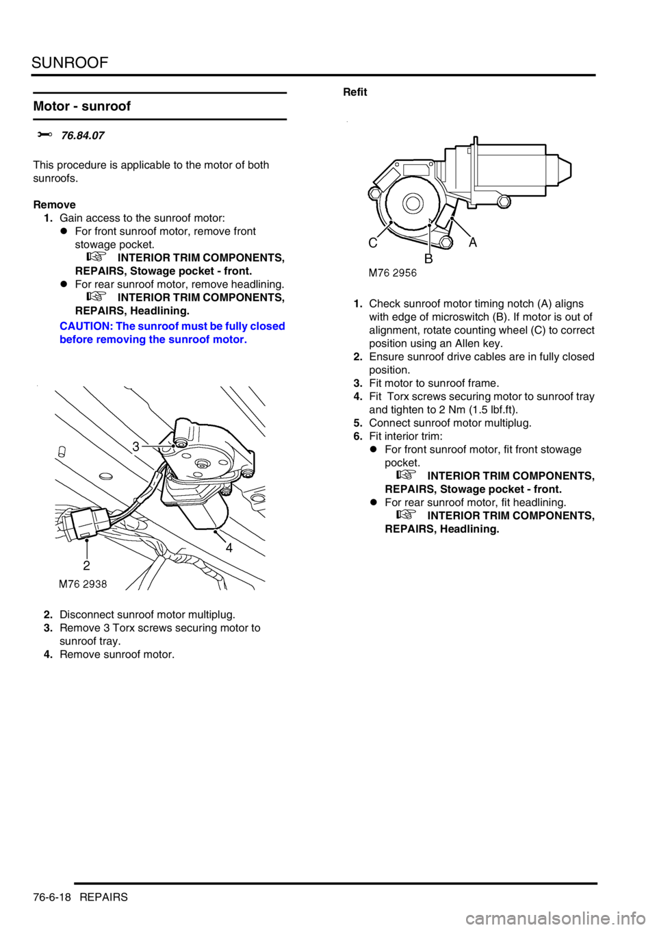
2.Disconnect sunroof motor multiplug.
3.Remove 3 Torx screws securing motor to
sunroof tray.
4.Remove sunroof motor. Refit
1.Check sunroof motor timing notch (A) aligns
with edge of microswitch (B). If motor is out of
alignment, rotate counting wheel (C) to correct
position using an Allen key.
2.Ensure sunroof drive cables are in fully closed
position.
3.Fit motor to sunroof frame.
4.Fit Torx screws securing motor to sunroof tray
and tighten to 2 Nm (1.5 lbf.ft).
5.Connect sunroof motor multiplug.
6.Fit interior trim:
lFor front sunroof motor, fit front stowage
pocket.
+ INTERIOR TRIM COMPONENTS,
REPAIRS, Stowage pocket - front.
lFor rear sunroof motor, fit headlining.
+ INTERIOR TRIM COMPONENTS,
REPAIRS, Headlining.