1999 LAND ROVER DISCOVERY CD changer
[x] Cancel search: CD changerPage 30 of 1529

CONTENTS
CONTENTS 27
WINDOWS ................................................................................................ 86-5-1
DESCRIPTION AND OPERATION
Electric windows block diagram ...................................................................................................... 86-5-1
Electric windows component layout ................................................................................................ 86-5-2
Description ...................................................................................................................................... 86-5-4
Operation ....................................................................................................................................... 86-5-11
REPAIRS
Switch - rear door .......................................................................................................................... 86-5-13
Switch - console ............................................................................................................................ 86-5-13
Switch - heated rear screen ............................................................................................................ 86-5-14
IN CAR ENTERTAINMENT ...................................................................... 86-6-1
DESCRIPTION AND OPERATION
ICE System Component layout ....................................................................................................... 86-6-1
Base and mid line ICE system control diagram .............................................................................. 86-6-2
High line ICE system control diagram ............................................................................................. 86-6-3
Description ...................................................................................................................................... 86-6-4
DESCRIPTION AND OPERATION
DVD Player Component Layout ...................................................................................................... 86-6-12
DVD Player Control Diagram .......................................................................................................... 86-6-14
Description ...................................................................................................................................... 86-6-16
Operation ........................................................................................................................................ 86-6-27
REPAIRS
Radio ............................................................................................................................................. 86-6-31
Speaker - low/full range - front door .............................................................................................. 86-6-32
Speaker - low range - rear door ..................................................................................................... 86-6-32
Switches - remote control - ICE .................................................................................................... 86-6-33
Amplifier - aerial .............................................................................................................................. 86-6-33
Speaker - mid range - front door ................................................................................................... 86-6-34
Speaker - high range - rear door ................................................................................................... 86-6-34
Amplifier - power ........................................................................................................................... 86-6-35
Speaker - tail door ......................................................................................................................... 86-6-36
CD autochanger ............................................................................................................................ 86-6-36
DVD screen/player unit .................................................................................................................. 86-6-37
Switch box - CD/DVD player ........................................................................................................... 86-6-38
HARNESSES ............................................................................................ 86-7-1
REPAIRS
Harness - injectors - diesel ............................................................................................................ 86-7-1
Harness - body .............................................................................................................................. 86-7-1
Harness - engine - V8 ..................................................................................................................... 86-7-8
Harness - engine - diesel ................................................................................................................ 86-7-12
Harness - main .............................................................................................................................. 86-7-15
Harness - main - DVD unit ............................................................................................................. 86-7-28
Harness - link - CD/DVD switch box ............................................................................................... 86-7-32
Page 425 of 1529

COOLING SYSTEM - V8
26-2-10 DESCRIPTION AND OPERATION
Operation
Coolant flow - Engine warm up
Refer to illustration.
+ COOLING SYSTEM - V8, DESCRIPTION AND OPERATION, Cooling system coolant flow.
During warm-up the coolant pump moves fluid through the cylinder block and it emerges from the inlet manifold outlet
pipe. From the outlet pipe, the warm coolant flow is prevented from flowing through the radiator because the
thermostat is closed. The coolant is directed into the heater circuit.
Some coolant from the by-pass pipe can pass through small sensing holes in the flow valve. The warm coolant enters
a tube in the thermostat housing and surrounds 90% of the thermostat sensitive area. Cold coolant returning from the
radiator bottom hose conducts through 10% of the thermostat sensitive area. In cold ambient temperatures the engine
temperature can be raised by up to 10°C (50°F) to compensate for the heat loss of the 10% exposure to the cold
coolant returning from the radiator bottom hose.
At engine idle speed, the by-pass valve is closed only allowing the small flow through the sensing holes. As the engine
speed increases above idle, the greater flow and pressure from the pump overcomes the light spring and opens the
by-pass flow valve. The flow valve opens to meet the engines cooling needs at higher engine speeds and prevents
excess pressure in the system. With the thermostat closed, maximum flow is directed through the heater circuit.
The heater matrix acts as a heat exchanger reducing coolant temperature as it passes through the matrix. Coolant
emerges from the matrix and flows into the coolant pump feed pipe and recirculated around the heater circuit. In this
condition the cooling system is operating at maximum heater performance.
Coolant flow - Engine hot
As the coolant temperature increases the thermostat opens. This allows some coolant from the outlet housing to flow
through the top hose and into the radiator to be cooled. The hot coolant flows from the left tank in the radiator, along
the tubes to the right tank. The air flowing through the fins between the tubes cools the coolant as it passes through
the radiator.
A controlled flow of the lower temperature coolant is drawn by the pump and blended with hot coolant from the by-
pass and the heater return pipes in the pump feed pipe. The pump then passes this coolant into the cylinder block to
cool the cylinders.
Page 983 of 1529

INTERIOR TRIM COMPONENTS
76-3-18 REPAIRS
Carpet - front
$% 76.49.02
Remove
1. Models with premium ICE: Remove power
amplifier.
+ IN CAR ENTERTAINMENT,
REPAIRS, Amplifier - power.
2. Models with premium ICE: Remove CD
autochanger.
+ IN CAR ENTERTAINMENT,
REPAIRS, CD autochanger.
3.Remove centre console.
lFor models with manual gearbox:
+ INTERIOR TRIM COMPONENTS,
REPAIRS, Console - centre - manual
models.
lFor models with automatic gearbox:
+ INTERIOR TRIM COMPONENTS,
REPAIRS, Console - centre - automatic
models.
4.Remove both lower 'A' post trim panels.
5.Remove finisher from both front carpet
retainers.
6.Remove 8 screws securing front carpet
retainers to floor.
7.Remove front carpet retainers.
8.Remove 2 nuts securing main body harness to
transmission tunnel.
9.With assistance release and remove carpet.Refit
1.With assistance position carpet.
2.Secure main body harness to transmission
tunnel with nuts.
3.Position front carpet retainers and secure to
floor with screws.
4.Fit finishers to front carpet retainers
5.Fit both lower 'A' post trim panels.
6.Fit centre console.
lFor models with manual gearbox:
+ INTERIOR TRIM COMPONENTS,
REPAIRS, Console - centre - manual
models.
lFor models with automatic gearbox:
+ INTERIOR TRIM COMPONENTS,
REPAIRS, Console - centre - automatic
models.
7. Models with premium ICE: Fit CD
autochanger.
+ IN CAR ENTERTAINMENT,
REPAIRS, CD autochanger.
8. Models with premium ICE: Fit power
amplifier.
+ IN CAR ENTERTAINMENT,
REPAIRS, Amplifier - power.
Page 1102 of 1529

PANEL REPAIRS
REPAIRS 77-2-35
'A' post assembly
In this procedure, the front wing and the valance
outer reinforcement (rear section) are replaced in
conjunction with the 'A' post assembly. The dash side
assembly can also be replaced in this procedure if
required.
Remove
1.Disconnect both battery leads, negative lead
first.
2.Disconnect leads/multiplug from alternator.
3.Remove bonnet.
4.Remove front wing.
+ EXTERIOR FITTINGS, REPAIRS,
Wing - front - up to 03MY.
5.Remove RH or LH front door.
+ DOORS, REPAIRS, Door - front.
6.Remove RH or LH sill finisher.
7.Remove windscreen.
+ SCREENS, REPAIRS, Windscreen.
8. Diesel models: Remove ECM.
+ ENGINE MANAGEMENT SYSTEM -
Td5, REPAIRS, Engine control module
(ECM).
9.Remove RH or LH 'A' post inner finishers and
disconnect speaker multiplug (if fitted).
10.Release sunroof drain tube and position aside.
11.Remove RH or LH front seat.
+ SEATS, REPAIRS, Seat - front.
12. RH side: Remove CD autochanger.
+ IN CAR ENTERTAINMENT,
REPAIRS, CD autochanger.
13.Remove fascia.
+ INTERIOR TRIM COMPONENTS,
REPAIRS, Fascia.
14. Driver's side: Remove steering column
support bracket.
15.Remove relevant wiring from 'A' post.
16.Remove tread plate from front door aperture.
17.Release front carpet and position aside.
18.Remove front door aperture seal.
19.Remove engine bulkhead insulation.Repair
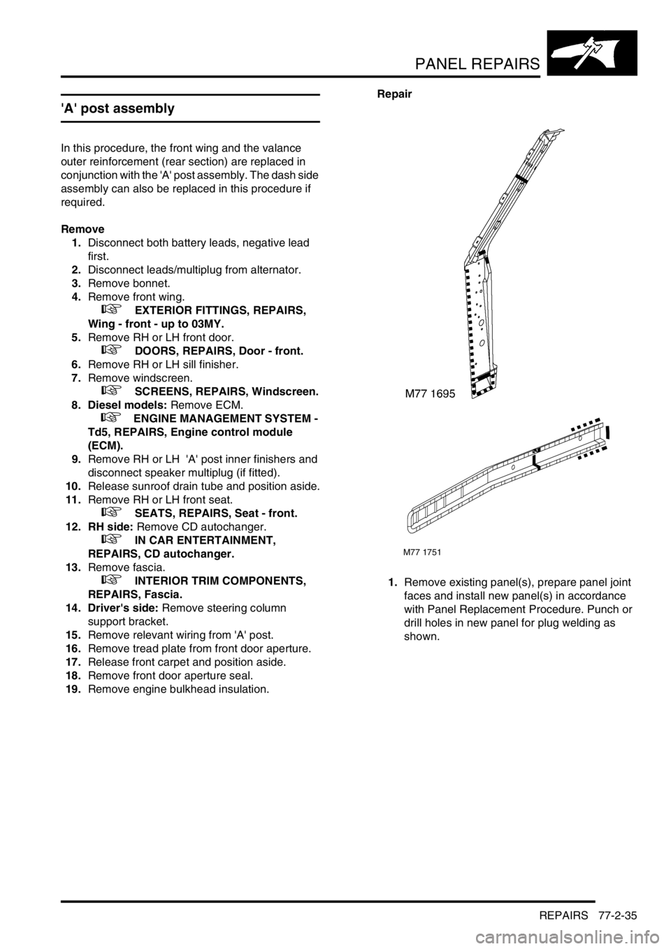
1.Remove existing panel(s), prepare panel joint
faces and install new panel(s) in accordance
with Panel Replacement Procedure. Punch or
drill holes in new panel for plug welding as
shown.
M77 1751
Page 1103 of 1529

PANEL REPAIRS
77-2-36 REPAIRS
Refit
1.Fit insulation pad to engine bulkhead.
2.Fit front door aperture seal.
3.Position front carpet and fit tread plate to front
door aperture.
4.Fit wiring to 'A' post.
5. Driver's side: Fit steering column support
bracket.
6.Fit fascia.
+ INTERIOR TRIM COMPONENTS,
REPAIRS, Fascia.
7. RH side: Fit CD autochanger.
+ IN CAR ENTERTAINMENT,
REPAIRS, CD autochanger.
8.Fit RH or LH front seat.
+ SEATS, REPAIRS, Seat - front.
9.Fit sunroof drain tube.
10.Connect multiplug to speaker (if fitted) and fit
finisher to 'A' post.
11. Diesel models: Fit ECM.
+ ENGINE MANAGEMENT SYSTEM -
Td5, REPAIRS, Engine control module
(ECM).
12.Fit windscreen.
+ SCREENS, REPAIRS, Windscreen.
13.Fit sill finisher.
14.Fit front door.
+ DOORS, REPAIRS, Door - front.
15.Fit front wing.
+ EXTERIOR FITTINGS, REPAIRS,
Wing - front - up to 03MY.
16.Fit bonnet.
17.Connect leads/multiplug to alternator.
18.Connect battery leads, negative lead last.
Page 1105 of 1529

PANEL REPAIRS
77-2-38 REPAIRS
Sill outer assembly
Remove
1.Disconnect both battery leads, negative lead
first.
2.Disconnect leads/multiplug from alternator.
3.Remove RH or LH front wing.
+ EXTERIOR FITTINGS, REPAIRS,
Wing - front - up to 03MY.
4.Remove RH or LH front door.
+ DOORS, REPAIRS, Door - front.
5.Remove RH or LH rear door.
+ DOORS, REPAIRS, Door - rear.
6.Remove RH or LH sill finisher.
7.Remove RH or LH 'A' post inner lower
finishers.
8.Remove RH or LH front seat.
+ SEATS, REPAIRS, Seat - front.
9. LH side: Remove power amplifier and EAT
ECU.
+ IN CAR ENTERTAINMENT,
REPAIRS, Amplifier - power.
10. RH side: Remove CD autochanger.
+ IN CAR ENTERTAINMENT,
REPAIRS, CD autochanger.
11.Remove rear seats.
+ SEATS, REPAIRS, Seat - rear.
12.Remove RH or LH front seat belt.
+ RESTRAINT SYSTEMS, REPAIRS,
Seat belt - front.
13.Remove tread plates from front and rear door
apertures.
14.Release carpet and position aside.
15.Remove front and rear door aperture seals.
16.Release relevant wiring from 'A' post, 'B/C' post
and sill areas, and position aside.
17.Remove loadspace lower trim casing.
+ INTERIOR TRIM COMPONENTS,
REPAIRS, Trim casing - side - loadspace.
18. RH side: Remove lower ACE accelerometer.
+ FRONT SUSPENSION, REPAIRS,
Accelerometer - ACE - lower.
19. LH side: Remove SLS air compressor unit.
+ REAR SUSPENSION, REPAIRS,
Compressor unit - air - SLS.
20. Models with rear A/C: Recover refrigerant
from A/C system and remove A/C pipes from
LH sill.
+ AIR CONDITIONING, REFRIGERANT
RECOVERY, RECYCLING AND
RECHARGING, Refrigerant recovery,
recycling and recharging.
21.Remove 2 bolts securing body to chassis.Repair
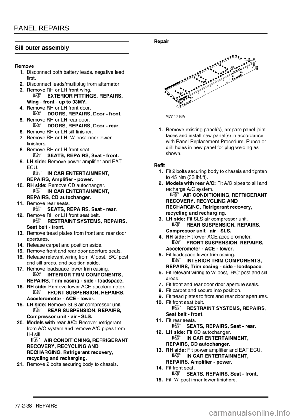
1.Remove existing panel(s), prepare panel joint
faces and install new panel(s) in accordance
with Panel Replacement Procedure. Punch or
drill holes in new panel for plug welding as
shown.
Refit
1.Fit 2 bolts securing body to chassis and tighten
to 45 Nm (33 lbf.ft).
2. Models with rear A/C: Fit A/C pipes to sill and
recharge A/C system.
+ AIR CONDITIONING, REFRIGERANT
RECOVERY, RECYCLING AND
RECHARGING, Refrigerant recovery,
recycling and recharging.
3. LH side: Fit SLS air compressor unit.
+ REAR SUSPENSION, REPAIRS,
Compressor unit - air - SLS.
4. RH side: Fit lower ACE accelerometer.
+ FRONT SUSPENSION, REPAIRS,
Accelerometer - ACE - lower.
5.Fit loadspace lower trim casing.
+ INTERIOR TRIM COMPONENTS,
REPAIRS, Trim casing - side - loadspace.
6.Fit relevant wiring to 'A' post, 'B/C' post and sill
areas.
7.Fit front and rear door door aperture seals.
8.Fit carpet and secure into position.
9.Fit tread plates to front and rear door apertures.
10.Fit front seat belt.
+ RESTRAINT SYSTEMS, REPAIRS,
Seat belt - front.
11.Fit rear seats.
+ SEATS, REPAIRS, Seat - rear.
12. LH side: Fit CD autochanger.
+ IN CAR ENTERTAINMENT,
REPAIRS, CD autochanger.
13. RH side: Fit power amplifier and EAT ECU.
+ IN CAR ENTERTAINMENT,
REPAIRS, Amplifier - power.
14.Fit front seat.
+ SEATS, REPAIRS, Seat - front.
15.Fit 'A' post inner lower finishers.
M77 1716A
Page 1107 of 1529

PANEL REPAIRS
77-2-40 REPAIRS
'B/C' post assembly
Remove
1.Disconnect both battery leads, negative lead
first.
2.Disconnect leads/multiplug from alternator.
3.Remove RH or LH rear door.
+ DOORS, REPAIRS, Door - rear.
4.Remove front door striker from 'B/C' post.
5.Remove RH or LH sill finisher.
6.Remove RH or LH front seat.
+ SEATS, REPAIRS, Seat - front.
7. RH side: Remove power amplifier.
+ IN CAR ENTERTAINMENT,
REPAIRS, Amplifier - power.
8. LH side: Remove CD autochanger.
+ IN CAR ENTERTAINMENT,
REPAIRS, CD autochanger.
9.Remove RH or LH front seat belt.
+ RESTRAINT SYSTEMS, REPAIRS,
Seat belt - front.
10.Remove RH or LH rear seat.
+ SEATS, REPAIRS, Seat - rear.
11.Remove head lining.
+ INTERIOR TRIM COMPONENTS,
REPAIRS, Headlining.
12.Remove tread plate from front and rear door
apertures.
13.Release carpet from fixings and position aside.
14.Remove front and rear door door aperture
seals.
15.Release relevant wiring from 'B/C' post and sill
areas and position aside.
16.Remove side drip rail finisher.Repair
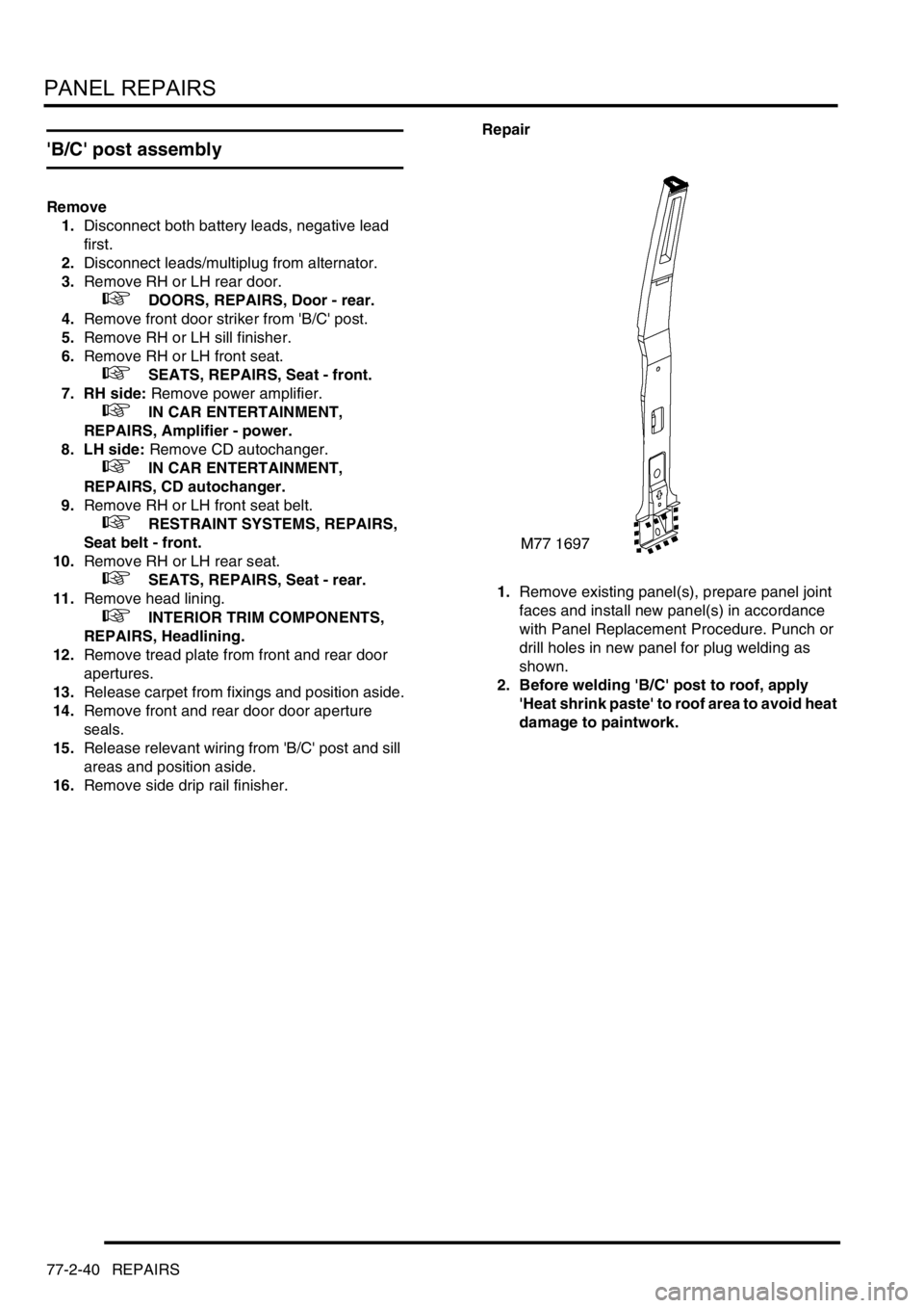
1.Remove existing panel(s), prepare panel joint
faces and install new panel(s) in accordance
with Panel Replacement Procedure. Punch or
drill holes in new panel for plug welding as
shown.
2. Before welding 'B/C' post to roof, apply
'Heat shrink paste' to roof area to avoid heat
damage to paintwork.
Page 1108 of 1529

PANEL REPAIRS
REPAIRS 77-2-41
Refit
1.Fit side drip rail finisher.
2.Fit wiring to 'B/C' post and sill areas.
3.Fit front and rear door door aperture seal.
4.Position carpet and secure with fixings.
5.Fit tread plates to front and rear door apertures.
6.Fit head lining.
+ INTERIOR TRIM COMPONENTS,
REPAIRS, Headlining.
7.Fit rear seat.
+ SEATS, REPAIRS, Seat - rear.
8.Fit front seat belt.
+ RESTRAINT SYSTEMS, REPAIRS,
Seat belt - front.
9. LH side: Fit CD autochanger.
+ IN CAR ENTERTAINMENT,
REPAIRS, CD autochanger.
10. RH side: Fit power amplifier.
+ IN CAR ENTERTAINMENT,
REPAIRS, Amplifier - power.
11.Fit RH or LH front seat.
+ SEATS, REPAIRS, Seat - front.
12.Fit sill finisher.
13.Fit front door striker to B/C post, fit Torx bolts
and tighten to 26 Nm (19 lbf.ft).
14.Fit rear door.
+ DOORS, REPAIRS, Door - rear.
15.Connect leads/multiplug to alternator.
16.Connect battery leads, negative lead last.
Panel body side assembly
Remove
1.Disconnect both battery leads, negative lead
first.
2.Disconnect leads/multiplug from alternator.
3.Remove loadspace side trim casing.
+ INTERIOR TRIM COMPONENTS,
REPAIRS, Trim casing - side - loadspace.
4.Remove head lining rear trim finisher.
5.Remove rear head rests, if fitted.
6.Remove body side rear glass.
+ SCREENS, REPAIRS, Glass - body
side - rear.
7.Remove rear bumper assembly.
+ EXTERIOR FITTINGS, REPAIRS,
Bumper assembly - rear - up to 03MY.
8.Remove rear bumper finisher.
9.Remove rear wheel arch liner.
+ EXTERIOR FITTINGS, REPAIRS,
Liner - wheel arch - rear.
10.Remove mud flap.
11.Remove tread plate from rear door aperture.
12.Remove rear door aperture seal.
13.Remove rear door striker from 'D' post.
14.Remove 'D' post outer trim finisher.
15.Remove wheel arch trim finisher.
16.Remove side drip rail finisher.
17. RH side: Remove tail door.
18. LH side: Remove tail door striker and setting
block from 'E' post.
19.Remove tail door tread plate.
20.Remove loadspace carpet retainer.
21.Remove tail door aperture seal.
22.Remove tail lamp.
+ LIGHTING, REPAIRS, Lamp - tail.
23. RH side: Remove fuel filler flap.
24. RH side: Remove fuel filler tube.
+ FUEL DELIVERY SYSTEM - V8,
REPAIRS, Filler tube - fuel.
25.Remove aerial amplifier.
26.Remove relevant wiring from body side area.