1999 LAND ROVER DISCOVERY suspension
[x] Cancel search: suspensionPage 1297 of 1529

BODY CONTROL UNIT
86-3-10 DESCRIPTION AND OPERATION
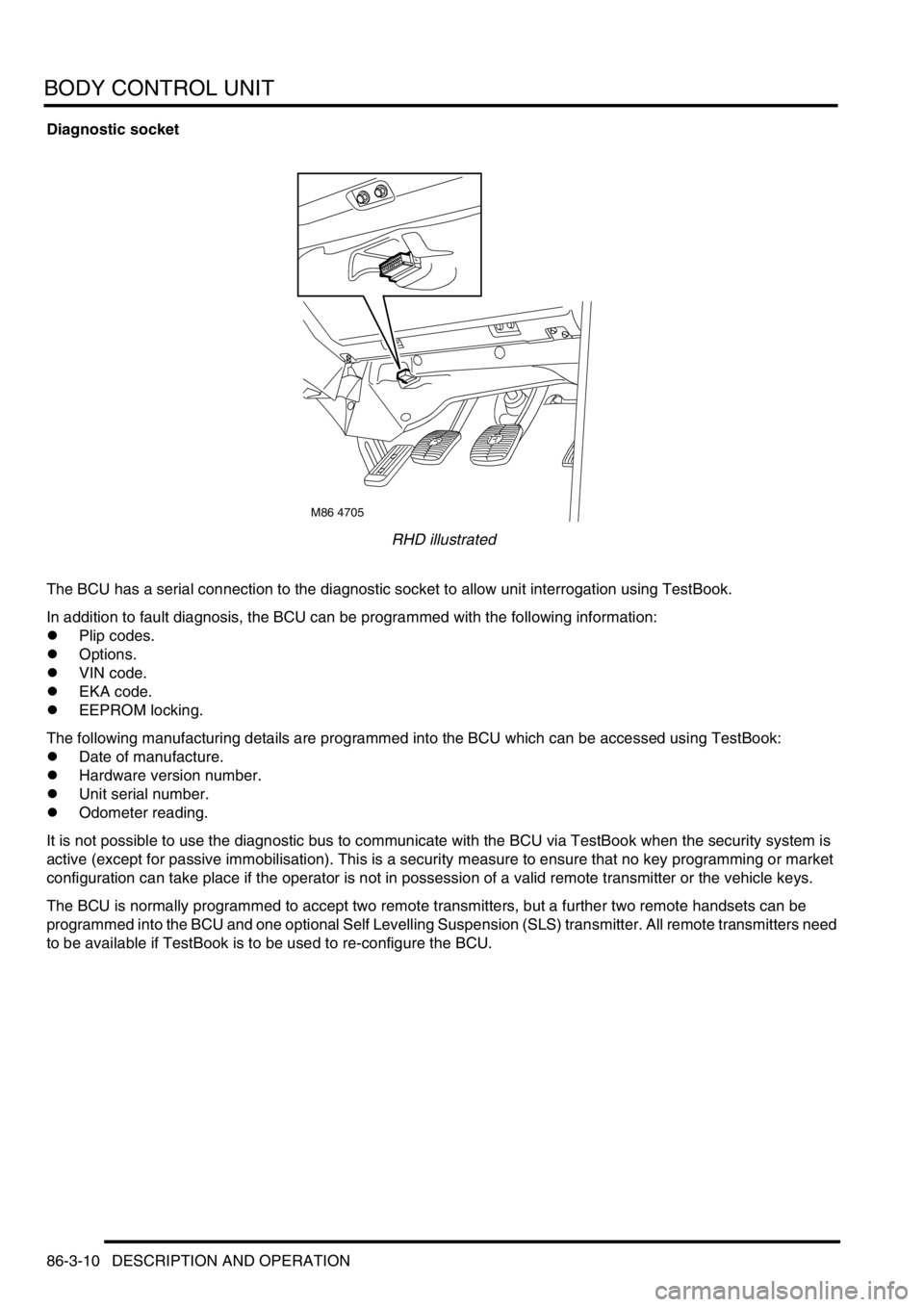
Diagnostic socket
RHD illustrated
The BCU has a serial connection to the diagnostic socket to allow unit interrogation using TestBook.
In addition to fault diagnosis, the BCU can be programmed with the following information:
lPlip codes.
lOptions.
lVIN code.
lEKA code.
lEEPROM locking.
The following manufacturing details are programmed into the BCU which can be accessed using TestBook:
lDate of manufacture.
lHardware version number.
lUnit serial number.
lOdometer reading.
It is not possible to use the diagnostic bus to communicate with the BCU via TestBook when the security system is
active (except for passive immobilisation). This is a security measure to ensure that no key programming or market
configuration can take place if the operator is not in possession of a valid remote transmitter or the vehicle keys.
The BCU is normally programmed to accept two remote transmitters, but a further two remote handsets can be
programmed into the BCU and one optional Self Levelling Suspension (SLS) transmitter. All remote transmitters need
to be available if TestBook is to be used to re-configure the BCU.
M86 4705
Page 1304 of 1529

BODY CONTROL UNIT
DESCRIPTION AND OPERATION 86-3-17
The existence of an intermediate state causes a fault code to be detected by the BCU. To reduce the chances of the
fault condition occurring while changing selector lever position, the inputs are debounced and only considered valid
when they have existed for at least 33 ms.
Transmission neutral selector
The transmission neutral sensor provides an earth signal to the BCU when the transfer box is in neutral. The earth
signal causes the BCU to operate an audible warning when the transfer box is in neutral with the ignition switched on.
+ TRANSFER BOX - LT230SE, DESCRIPTION AND OPERATION, Description.
Self levelling suspension and ABS
The BCU communicates with the SLABS ECU for several functions:
lAn output is provided from the SLABS ECU to the BCU to provide the logic conditions for issuing the SLS audible
warning.
lThe BCU receives an input from the SLABS ECU relating to the raise/ lower command from the remote handset.
+ REAR SUSPENSION, DESCRIPTION AND OPERATION, Description - SLS.
Hill descent control
The BCU provides an output signal to the SLABS ECU for automatic transmission in neutral for HDC control. The
BCU checks the status of the ignition and 'gearbox state' inputs and provides a 'Neutral selected' output. If the ignition
is on and 'gearbox state' is Neutral, the 'Neutral selected' output is on, otherwise 'Neutral selected' is off.
+ BRAKES, DESCRIPTION AND OPERATION, Description.
Heated screens
The Heated Front Screen (HFS) is fitted for some market destinations and is operated from a non-latching switch
located on the instrument pack cowl. The BCU will only allow the heated front screen to operate when the engine is
running and controls the time-out period for switching the circuit off.
The heated front screen operation can also be controlled from the Automatic Temperature Control (ATC) ECU on
vehicles fitted with air conditioning.
The heated rear window will only function when the engine is running, and is operated by a non-latching switch on the
instrument pack cowl. The heated rear window can also be operated by the ATC ECU on vehicles fitted with air
conditioning.
Interior courtesy lamps
The BCU controls the operation of the interior courtesy lamps. The courtesy lamps are situated in the front, mid and
rear areas of the headlining.
Fuel flap actuator
The BCU provides an earth path to the fuel flap release solenoid to allow the fuel filler flap to be opened. This is only
allowed if the alarm system is not set and all other conditions have been satisfied. The fuel flap release switch is
located in the fascia switch pack on vehicles up to 2003 model year or in the instrument pack binacle on vehicles from
2003 model year. The switch receives a voltage supply from the passenger compartment fuse box.
Page 1489 of 1529

INSTRUMENTS
88-6 DESCRIPTION AND OPERATION
The third warning lamp pack is located in the top right-hand side of the instrument pack and contains the following
warning lamps:
lSRS warning lamp.
lSLS off road mode warning lamp.
lTrailer warning lamp.
lGlow plug warning lamp.
lWater in fuel filter warning lamp.
lSeat belt warning lamp.
lTransmission high temperature warning lamp.
The fourth warning lamp pack is located underneath the tachometer of the instrument pack contains the following
warning lamps:
lOil pressure warning lamp.
lAlternator charge warning lamp.
lHDC fault warning lamp.
lSelf Levelling Suspension (SLS) warning lamp.
lActive Cornering Enhancement (ACE) warning lamp.
lGearbox manual/sport mode warning lamps.
The serial communication link is used to allow information to travel to and from the instrument pack, and it provides
the ability to configure the instrument pack to a specific market. It also allows the instrument pack to be controlled by
TestBook for diagnostics.
There are five market specific variants of the instrument pack:
lUnited Kingdom (UK).
lNorth American Specification (NAS).
lCanada.
lAustralia.
lRest Of the World (ROW), Gulf and Japan.
The main difference between the five markets is that the speedometer will indicate road speed in mph as major figures
and km/h as minor figures, km/h as major figures and mph as minor figures or km/h only.
When TestBook is used to diagnose the instrument pack it demands each of the dials and warning lamps to operate
in-turn so a visual check of their operation can be made.
CAUTION: The instrument pack must not be stored on its face side at any time. This is because the dials have
damping fluid within them to ensure smooth operation of the dials' indicator needles. This fluid will leak out.
Speedometer
The speedometer informs the driver of the current vehicle road speed. It has a Liquid Crystal Display (LCD) to show
odometer, trip meter and, on automatic gearbox models, the selected gear. The speedometer will not show speeds
of less than 1.5 mph (2.5 km/h).
There are three different market configurations:
lNAS and UK = mph as major figures km/h as minor figures.
lCanada = km/h as major figures mph as minor figures.
lROW and Australia = km/h only.
The Self Levelling and Anti-Lock Brake System (SLABS) ECU provides the signal input for the road speed. The signal
is at 8000 pulses per mile (1.6 kilometres).
Page 1509 of 1529

INSTRUMENTS
88-26 DESCRIPTION AND OPERATION
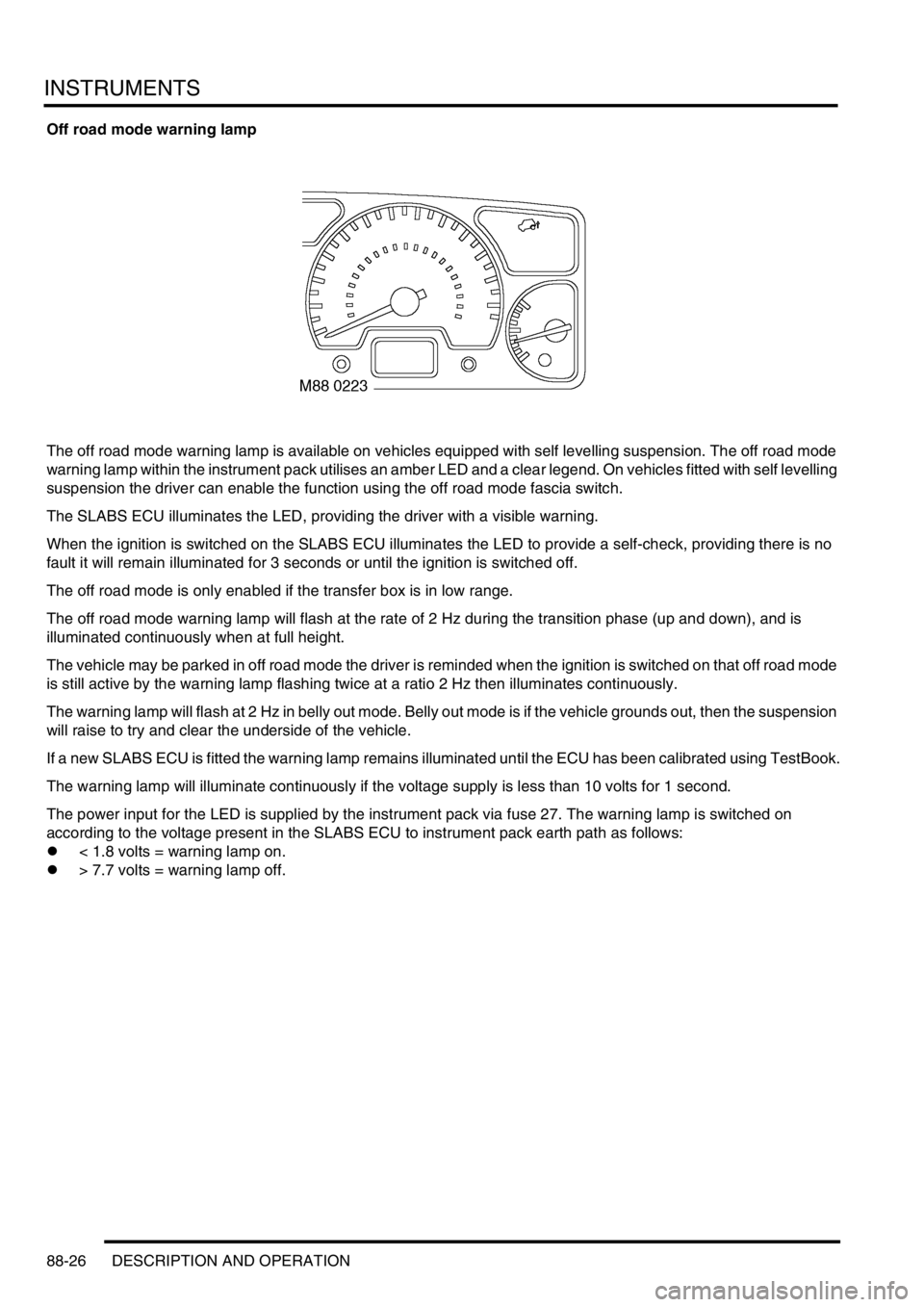
Off road mode warning lamp
The off road mode warning lamp is available on vehicles equipped with self levelling suspension. The off road mode
warning lamp within the instrument pack utilises an amber LED and a clear legend. On vehicles fitted with self levelling
suspension the driver can enable the function using the off road mode fascia switch.
The SLABS ECU illuminates the LED, providing the driver with a visible warning.
When the ignition is switched on the SLABS ECU illuminates the LED to provide a self-check, providing there is no
fault it will remain illuminated for 3 seconds or until the ignition is switched off.
The off road mode is only enabled if the transfer box is in low range.
The off road mode warning lamp will flash at the rate of 2 Hz during the transition phase (up and down), and is
illuminated continuously when at full height.
The vehicle may be parked in off road mode the driver is reminded when the ignition is switched on that off road mode
is still active by the warning lamp flashing twice at a ratio 2 Hz then illuminates continuously.
The warning lamp will flash at 2 Hz in belly out mode. Belly out mode is if the vehicle grounds out, then the suspension
will raise to try and clear the underside of the vehicle.
If a new SLABS ECU is fitted the warning lamp remains illuminated until the ECU has been calibrated using TestBook.
The warning lamp will illuminate continuously if the voltage supply is less than 10 volts for 1 second.
The power input for the LED is supplied by the instrument pack via fuse 27. The warning lamp is switched on
according to the voltage present in the SLABS ECU to instrument pack earth path as follows:
l< 1.8 volts = warning lamp on.
l> 7.7 volts = warning lamp off.
Page 1519 of 1529

INSTRUMENTS
88-36 DESCRIPTION AND OPERATION
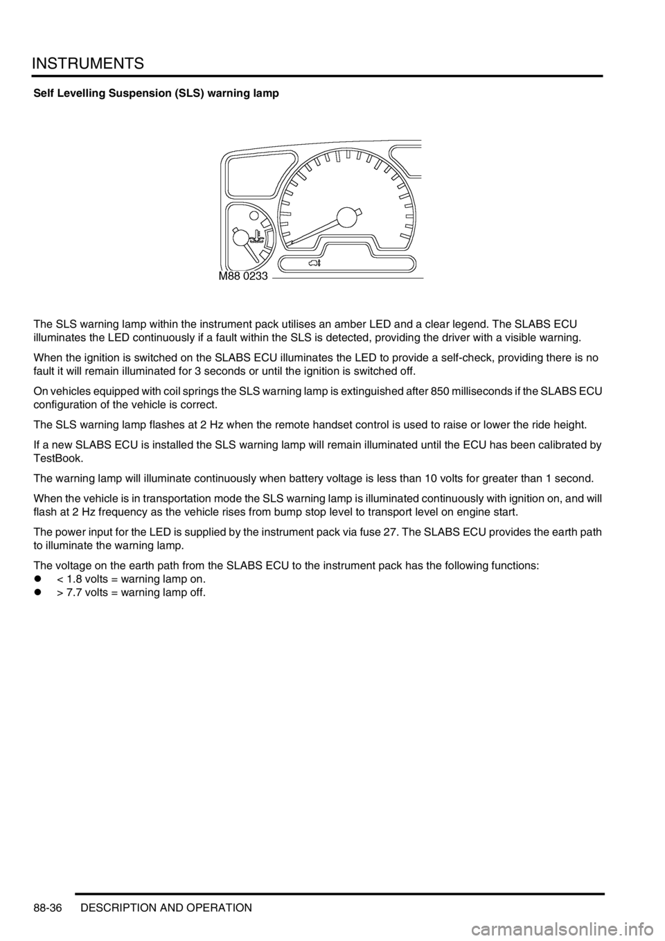
Self Levelling Suspension (SLS) warning lamp
The SLS warning lamp within the instrument pack utilises an amber LED and a clear legend. The SLABS ECU
illuminates the LED continuously if a fault within the SLS is detected, providing the driver with a visible warning.
When the ignition is switched on the SLABS ECU illuminates the LED to provide a self-check, providing there is no
fault it will remain illuminated for 3 seconds or until the ignition is switched off.
On vehicles equipped with coil springs the SLS warning lamp is extinguished after 850 milliseconds if the SLABS ECU
configuration of the vehicle is correct.
The SLS warning lamp flashes at 2 Hz when the remote handset control is used to raise or lower the ride height.
If a new SLABS ECU is installed the SLS warning lamp will remain illuminated until the ECU has been calibrated by
TestBook.
The warning lamp will illuminate continuously when battery voltage is less than 10 volts for greater than 1 second.
When the vehicle is in transportation mode the SLS warning lamp is illuminated continuously with ignition on, and will
flash at 2 Hz frequency as the vehicle rises from bump stop level to transport level on engine start.
The power input for the LED is supplied by the instrument pack via fuse 27. The SLABS ECU provides the earth path
to illuminate the warning lamp.
The voltage on the earth path from the SLABS ECU to the instrument pack has the following functions:
l< 1.8 volts = warning lamp on.
l> 7.7 volts = warning lamp off.