Page 836 of 1529
REAR SUSPENSION
REPAIRS 64-27
REPAIRS
Wheel hub
$% 64.15.01
Models with SLS:
WARNING: Ensure the air suspension system is
made safe before commencing work. Otherwise
the chassis may lower onto the bump stops
during repair.
Remove
1.Raise rear of vehicle.
WARNING: Do not work on or under a
vehicle supported only by a jack. Always
support the vehicle on safety stands.
2.Remove road wheel.
3.Release stake in drive shaft nut.
4.With an assistant depressing the brake pedal,
remove and discard drive shaft nut.
5.Remove rear brake disc.
+ BRAKES, REPAIRS, Brake disc -
rear.6.Disconnect ABS sensor multiplug.
7.Release harness from brake hose and hose
bracket.
8.Remove 4 bolts securing wheel hub to axle.
9.Release and remove wheel hub and drive shaft
assembly from axle. Remove and discard 'O'
ring from wheel hub.
Page 837 of 1529

REAR SUSPENSION
64-28 REPAIRS
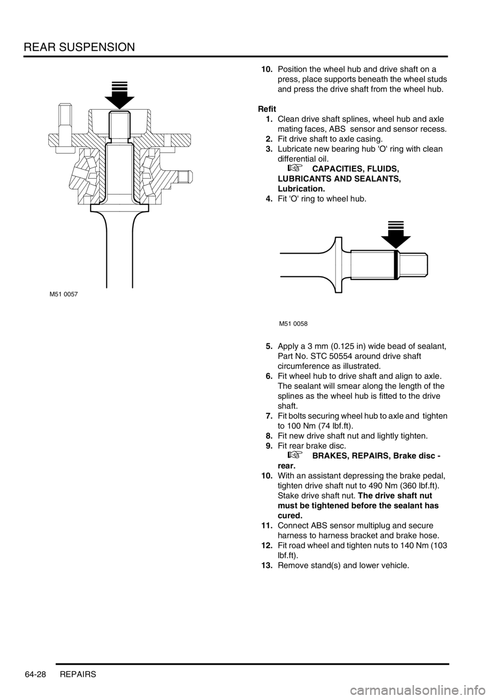
10.Position the wheel hub and drive shaft on a
press, place supports beneath the wheel studs
and press the drive shaft from the wheel hub.
Refit
1.Clean drive shaft splines, wheel hub and axle
mating faces, ABS sensor and sensor recess.
2.Fit drive shaft to axle casing.
3.Lubricate new bearing hub 'O' ring with clean
differential oil.
+ CAPACITIES, FLUIDS,
LUBRICANTS AND SEALANTS,
Lubrication.
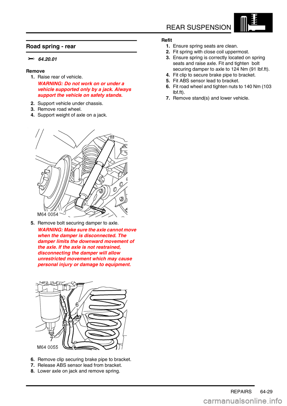
4.Fit 'O' ring to wheel hub.
5.Apply a 3 mm (0.125 in) wide bead of sealant,
Part No. STC 50554 around drive shaft
circumference as illustrated.
6.Fit wheel hub to drive shaft and align to axle.
The sealant will smear along the length of the
splines as the wheel hub is fitted to the drive
shaft.
7.Fit bolts securing wheel hub to axle and tighten
to 100 Nm (74 lbf.ft).
8.Fit new drive shaft nut and lightly tighten.
9.Fit rear brake disc.
+ BRAKES, REPAIRS, Brake disc -
rear.
10.With an assistant depressing the brake pedal,
tighten drive shaft nut to 490 Nm (360 lbf.ft).
Stake drive shaft nut. The drive shaft nut
must be tightened before the sealant has
cured.
11.Connect ABS sensor multiplug and secure
harness to harness bracket and brake hose.
12.Fit road wheel and tighten nuts to 140 Nm (103
lbf.ft).
13.Remove stand(s) and lower vehicle.
M51 0057
M51 0058
Page 838 of 1529

REAR SUSPENSION
REPAIRS 64-29
Road spring - rear
$% 64.20.01
Remove
1.Raise rear of vehicle.
WARNING: Do not work on or under a
vehicle supported only by a jack. Always
support the vehicle on safety stands.
2.Support vehicle under chassis.
3.Remove road wheel.
4.Support weight of axle on a jack.
5.Remove bolt securing damper to axle.
WARNING: Make sure the axle cannot move
when the damper is disconnected. The
damper limits the downward movement of
the axle. If the axle is not restrained,
disconnecting the damper will allow
unrestricted movement which may cause
personal injury or damage to equipment.
6.Remove clip securing brake pipe to bracket.
7.Release ABS sensor lead from bracket.
8.Lower axle on jack and remove spring.Refit
1.Ensure spring seats are clean.
2.Fit spring with close coil uppermost.
3.Ensure spring is correctly located on spring
seats and raise axle. Fit and tighten bolt
securing damper to axle to 124 Nm (91 lbf.ft).
4.Fit clip to secure brake pipe to bracket.
5.Fit ABS sensor lead to bracket.
6.Fit road wheel and tighten nuts to 140 Nm (103
lbf.ft).
7.Remove stand(s) and lower vehicle.
Page 839 of 1529

REAR SUSPENSION
64-30 REPAIRS
Air spring - SLS
$% 64.21.01
Remove
1.Using TestBook, depressurise SLS air system.
After depressurisation, approximately 1 bar
(15 lbf.in
2) air pressure remains in the
system.
2.Raise rear of vehicle and support under
chassis.
WARNING: Do not work on or under a
vehicle supported only by a jack. Always
support the vehicle on safety stands.
3.Remove road wheel.
4.Remove 2 clips securing air spring to chassis.
5.Collapse air spring and disconnect pipe from
top of air spring.
CAUTION: Always fit plugs to open
connections to prevent contamination.
6.Rotate air spring, to unlock from axle and
remove from vehicle.
7.Remove connector from pipe.Refit
1.Clean mating faces of air spring, axle and
chassis.
CAUTION: Check air bag for signs of
damage. If air bag is damaged, air spring
must be replaced.
2.Fit pipe connector to air spring.
3.Locate air spring on axle and rotate 90° to fully
engage bayonet fitting.
4.Connect pipe to top of air spring.
5.Engage top locating pins of air spring in chassis
and secure with clips.
6.Repressurise SLS air system using TestBook.
WARNING: Eye protection must be worn
during the repressurisation procedure.
7.Fit road wheel and tighten nuts to 140 Nm (103
lbf.ft).
8.Remove stand(s) and lower vehicle.
Page 840 of 1529

REAR SUSPENSION
REPAIRS 64-31
Damper - rear
$% 64.30.02
Remove
1.Raise rear of vehicle and support under
chassis.
WARNING: Do not work on or under a
vehicle supported only by a jack. Always
support the vehicle on safety stands.
2.Remove road wheel.
3.Support weight of axle on a jack.
4.Remove 2 bolts securing damper to axle and
chassis.
WARNING: Make sure the axle cannot move
when the damper is disconnected. The
damper limits the downward movement of
the axle. If the axle is not restrained,
disconnecting the damper will allow
unrestricted movement which may cause
personal injury or damage to equipment.
5.Compress damper and remove from vehicle.
Refit
1.Locate damper in axle and fit lower bolt, extend
damper to chassis and fit top bolt.
2.Tighten damper bolts to 125 Nm (92 lbf.ft).
3.Lower axle and remove jack.
4.Fit road wheel and tighten nuts to 140 Nm (103
lbf.ft).
5.Remove stand(s) and lower vehicle.
Bushes - radius arm
$% 64.35.29
Models with SLS:
WARNING: Ensure the air suspension system is
made safe before commencing work. Otherwise
the chassis may lower onto the bump stops
during repair.
Remove
1.Raise rear of vehicle.
WARNING: Do not work on or under a
vehicle supported only by a jack. Always
support the vehicle on safety stands.
2.Remove road wheel(s).
3. Models with SLS: Remove nut and bolt
securing height sensor link to radius arm.
4.Remove nut and bolt securing radius arm to
chassis.
5.Remove 2 nuts securing radius arm to axle.
6.Remove rear bolt and lower radius arm.
Page 841 of 1529
REAR SUSPENSION
64-32 REPAIRS
7.Remove front bolt from radius arm and remove
radius arm from axle.
8.Using LRT-60-011/1 and LRT-60-011/2 press
out bush from rear end of radius arm.
9.Using LRT-60-034/1 press out bushes from
axle end of radius arm.
Refit
1.Clean and lubricate bush and radius arm
mating faces.2.Using LRT-60-011/1, LRT-60-011/2 and LRT-
60-011/3 press bush into rear end of radius
arm.
3.Using LRT-60-034/1 press front radius arm
bush into LRT-60-034/2, until aproximately
2mm of bush is protruding from opposite end
of tool.
Page 842 of 1529
REAR SUSPENSION
REPAIRS 64-33
4.Position LRT-60-034/2 over radius arm and
locate bush to aperture.
5.With assistance, press bush into aperture.
6.Repeat above operation for remaining bush.
7.Position radius arm to vehicle and fit securing
nuts and bolts, do not tighten at this stage.
CAUTION: Nuts and bolts must be tightened
with the weight of the vehicle on the
suspension.
8. Models with SLS: Position height sensor link
to radius arm and tighten nut and bolt to 25 Nm
(18 lbf.ft).
9.Fit road wheel and tighten nuts to 140 Nm (103
lbf.ft).
10.Remove stands and lower vehicle.
11.Tighten radius arm nuts and bolts to 230 Nm
(170 lbf.ft).
Page 843 of 1529

REAR SUSPENSION
64-34 REPAIRS
Bushes - Watts linkage
$% 64.35.35
Models with SLS:
WARNING: Ensure the air suspension system is
made safe before commencing work. Otherwise
the chassis may lower onto the bump stops
during repair.
Remove
1.Raise rear of vehicle.
WARNING: Do not work on or under a
vehicle supported only by a jack. Always
support the vehicle on safety stands.
2.Remove 3 nuts and bolts securing Watts
linkage to axle and chassis and remove Watts
linkage.
3.Remove 2 nuts and bolts securing transverse
links to pivot housing and remove links from
pivot housing. 4.Use LRT-60-010/1 and LRT-60-010/3 to press
bushes from transverse links and pivot
housing.
Refit
1.Clean bush locations in transverse links and
pivot housing.
2.Using LRT-60-010/1 and LRT-60-010/2press
new bushes into transverse links and pivot
housing.
3.Position transverse links to pivot housing and
tighten bolts to 155 Nm (114 lbf.ft).
4.Position Watts linkage to axle and chassis. Fit
bolts but do not tighten at this stage.
5.Remove stand(s) and lower vehicle.
6.Tighten bolts securing pivot housing to axle to
230 Nm (170 lbf.ft). Tighten bolts securing
transverse links to chassis to 140 Nm (103
lbf.ft).
CAUTION: Nuts and bolts must be tightened
with weight of vehicle on suspension.