1999 LAND ROVER DISCOVERY suspension
[x] Cancel search: suspensionPage 852 of 1529

REAR SUSPENSION
REPAIRS 64-43
Refit
1.Clean bush locations in long arm.
2.Use suitable adaptors to press new actuator
rod end bush into long arm. Ensure bush is
correctly aligned.
3.Align slots in new slipper bush halves with
those in long arm. Carefully press both halves
of slipper bush into long arm. Ensure the
sealing rings on the bush faces are not
damaged.
4.Clean long arm and mating face on torsion bar.
5.Fit long arm to torsion bar. Restrain torsion bar
and tighten bolt to 180 Nm (133 lbf.ft).
6.Ensure actuator and bushes are clean.
7.Fit actuator and tighten nut and bolt securing
actuator to short arm to 180 Nm (133 lbf.ft).
8.Using LRT-60-009 , fit and tighten nut securing
actuator push rod to long arm to 48 Nm (35
lbf.ft).
9.With assistance, position torsion bar and
actuator to vehicle and fit torsion bar clamps.
Tighten torsion bar clamp bolts to 45 Nm (33
lbf.ft).
10.Connect pipes to actuator with cap nuts and
new sealing washers. Tighten cap nuts to 29
Nm (21 lbf.ft). Ensure pipes are not under
tension or kinked.
11.Fit anti-roll bar links to torsion bar and tighten
nuts to 50 Nm (37 lbf.ft).
12.Ensure washer is in place on lower ball joint of
each anti-roll bar link and connect lower ball
joints to axle. Tighten nuts to 100 Nm (74 lbf.ft).
13.Renew ACE high pressure filter.
+ FRONT SUSPENSION, REPAIRS,
Filter - high pressure - ACE.
14.Lower vehicle.
15.Bleed ACE hydraulic system.
+ FRONT SUSPENSION,
ADJUSTMENTS, ACE hydraulic system
bleeding.
Page 871 of 1529

BRAKES
70-18 DESCRIPTION AND OPERATION
The SLABS ECU continually calculates vehicle speed using the wheel speed inputs from all four ABS sensors. The
calculated vehicle speed is then used as a reference against which individual wheel speeds are monitored for
unacceptable acceleration or deceleration. The ABS sensor inputs are also used by the SLABS ECU to detect vehicle
deceleration rate, vehicle cornering rate and rough terrain.
The engaged forward gear and (on manual gearbox models) the clutch status are computed from the engine data
input, the engine speed input and vehicle speed. Reverse gear status is provided by an input from the reverse lamp
switch (manual gearbox models) or the BCU (automatic gearbox models). On automatic models, the BCU also
provides the neutral selected input.
In addition to controlling the brake related functions, the SLABS ECU:
lControls the operation of the self levelling suspension (SLS) system (where fitted).
+ REAR SUSPENSION, DESCRIPTION AND OPERATION, Description.
lOn V8 models, outputs a rough road signal to the ECM when traversing rough terrain.
lOutputs a vehicle speed signal.
The vehicle speed signal is output to the following systems (where fitted):
lActive Cornering Enhancement.
+ FRONT SUSPENSION, DESCRIPTION AND OPERATION, Description - ACE.
lAir conditioning.
+ AIR CONDITIONING, DESCRIPTION AND OPERATION, Description.
lCruise control.
+ ENGINE MANAGEMENT SYSTEM - Td5, DESCRIPTION AND OPERATION, Description.
+ ENGINE MANAGEMENT SYSTEM - V8, DESCRIPTION AND OPERATION, Description - engine
management.
lEngine management.
+ ENGINE MANAGEMENT SYSTEM - Td5, DESCRIPTION AND OPERATION, Description.
+ ENGINE MANAGEMENT SYSTEM - V8, DESCRIPTION AND OPERATION, Description - engine
management.
lIn-car entertainment.
+ IN CAR ENTERTAINMENT, DESCRIPTION AND OPERATION, Description.
lInstrument pack.
+ INSTRUMENTS, DESCRIPTION AND OPERATION, Description.
5 Front right inlet solenoid valve Output
6 Shuttle valve switches Input
7 Rear left outlet solenoid valve Output
8 Rear left inlet solenoid valve Output
9 Centre differential lock switch Input
10 Rear right outlet solenoid valve Output
11 Rear right inlet solenoid valve Output
12 Brake lamp relay Output
15 Return pump relay Output
C0655
7 Audible warning Output
10 Engine speed Input
Connector and pins not listed are either not used or used by the self levelling suspension system.
+ REAR SUSPENSION, DESCRIPTION AND OPERATION, Description.
Connector/Pin
No.Description Input/Output
Page 901 of 1529

BRAKES
70-48 REPAIRS
Sensor – ABS – front
$% 70.65.30
ABS sensor is supplied fitted to wheel hub and
must not be removed.
Remove
1.Remove wheel hub.
+ FRONT SUSPENSION, REPAIRS,
Wheel hub.
Refit
1.Fit wheel hub.
+ FRONT SUSPENSION, REPAIRS,
Wheel hub.
Sensor – ABS – rear
$% 70.65.31
ABS sensor is supplied fitted to wheel hub and
must not be removed.
Remove
1.Remove wheel hub.
+ REAR SUSPENSION, REPAIRS,
Wheel hub.
Refit
1.Fit wheel hub.
+ REAR SUSPENSION, REPAIRS,
Wheel hub.
Page 1096 of 1529
PANEL REPAIRS
REPAIRS 77-2-29
Refit
1. Models with A/C: Fit A/C pipes and recharge
A/C system.
+ AIR CONDITIONING, REFRIGERANT
RECOVERY, RECYCLING AND
RECHARGING, Refrigerant recovery,
recycling and recharging.
2.Fit harness to valance.
3.Fit brake pipes to valance.
4.Fit ABS modulator.
+ BRAKES, REPAIRS, Modulator unit
- ABS.
5.Fit PAS/ACE reservoir, refill fluids to correct
levelsand bleed ACE system.
+ FRONT SUSPENSION,
ADJUSTMENTS, ACE hydraulic system
bleeding.
+ CAPACITIES, FLUIDS,
LUBRICANTS AND SEALANTS, Fluids.
6.Fit air filter assembly.
+ ENGINE MANAGEMENT SYSTEM -
V8, REPAIRS, Air cleaner assembly.
+ ENGINE MANAGEMENT SYSTEM -
Td5, REPAIRS, Air filter assembly.
7.Fit front wing.
+ EXTERIOR FITTINGS, REPAIRS,
Wing - front - up to 03MY.
+ EXTERIOR FITTINGS, REPAIRS,
Wing - front - from 03MY.
8.Connect leads/multiplug to alternator.
9.Connect battery leads, negative lead last.
Valance upper assembly - RH
In this procedure, the front wing and the valance
outer reinforcement are replaced in conjunction with
the RH valance upper assembly.
Remove
1.Disconnect both battery leads, negative lead
first.
2.Disconnect leads/multiplug from alternator.
3.Remove front wing.
+ EXTERIOR FITTINGS, REPAIRS,
Wing - front - up to 03MY.
+ EXTERIOR FITTINGS, REPAIRS,
Wing - front - from 03MY.
4.Remove battery.
+ CHARGING AND STARTING,
REPAIRS, Battery.
5.Remove battery tray.
6.Remove fuse box.
7.Release expansion tank from fixings and
position aside.
8.Release harness from valance and position
aside.
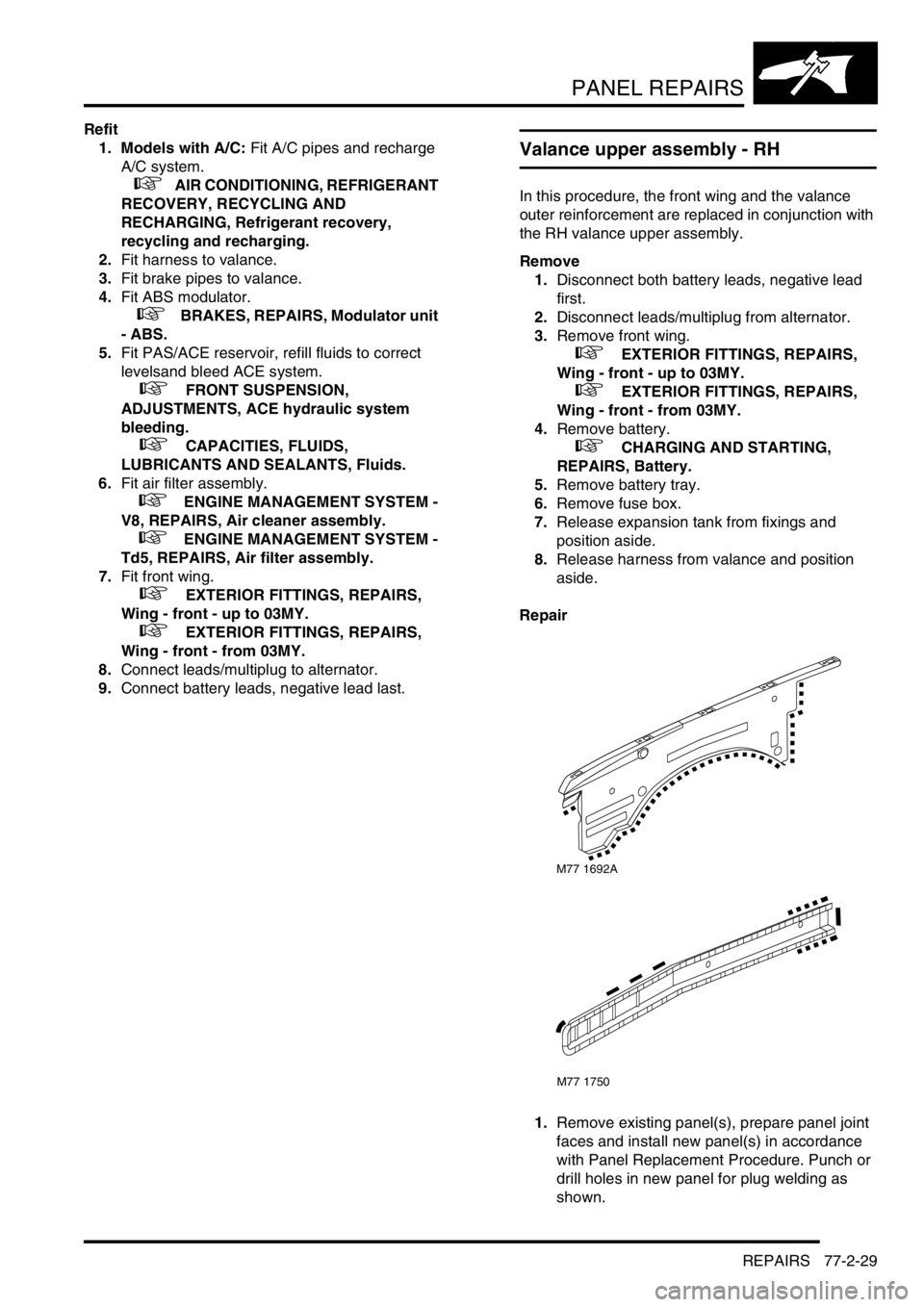
Repair
1.Remove existing panel(s), prepare panel joint
faces and install new panel(s) in accordance
with Panel Replacement Procedure. Punch or
drill holes in new panel for plug welding as
shown.
M77 1692A
M77 1750
Page 1098 of 1529
PANEL REPAIRS
REPAIRS 77-2-31
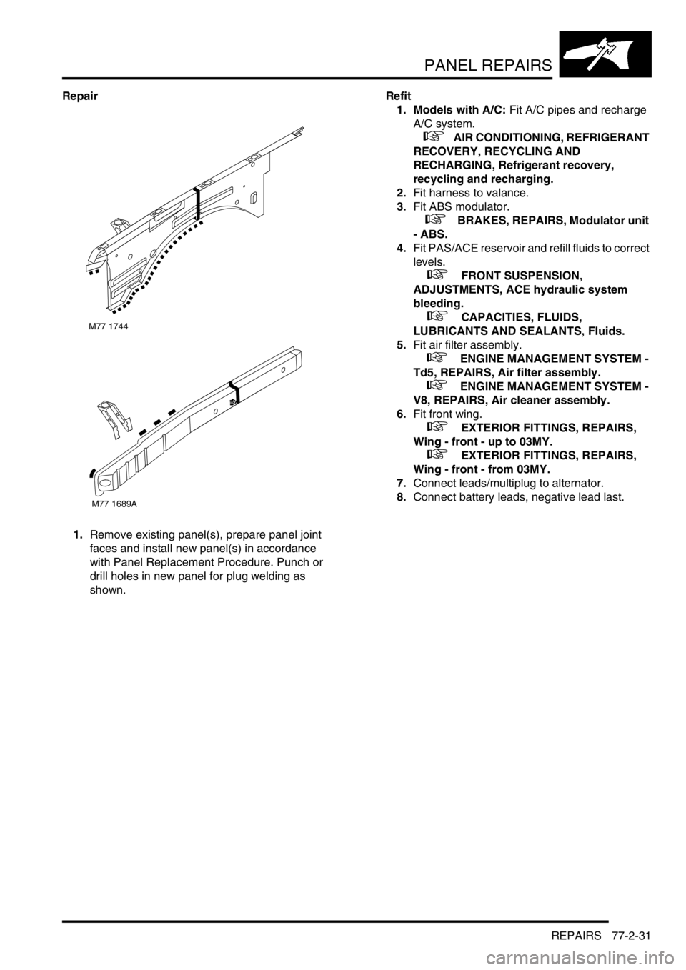
Repair
1.Remove existing panel(s), prepare panel joint
faces and install new panel(s) in accordance
with Panel Replacement Procedure. Punch or
drill holes in new panel for plug welding as
shown.Refit
1. Models with A/C: Fit A/C pipes and recharge
A/C system.
+ AIR CONDITIONING, REFRIGERANT
RECOVERY, RECYCLING AND
RECHARGING, Refrigerant recovery,
recycling and recharging.
2.Fit harness to valance.
3.Fit ABS modulator.
+ BRAKES, REPAIRS, Modulator unit
- ABS.
4.Fit PAS/ACE reservoir and refill fluids to correct
levels.
+ FRONT SUSPENSION,
ADJUSTMENTS, ACE hydraulic system
bleeding.
+ CAPACITIES, FLUIDS,
LUBRICANTS AND SEALANTS, Fluids.
5.Fit air filter assembly.
+ ENGINE MANAGEMENT SYSTEM -
Td5, REPAIRS, Air filter assembly.
+ ENGINE MANAGEMENT SYSTEM -
V8, REPAIRS, Air cleaner assembly.
6.Fit front wing.
+ EXTERIOR FITTINGS, REPAIRS,
Wing - front - up to 03MY.
+ EXTERIOR FITTINGS, REPAIRS,
Wing - front - from 03MY.
7.Connect leads/multiplug to alternator.
8.Connect battery leads, negative lead last.
M77 1744
M77 1689A
Page 1105 of 1529
PANEL REPAIRS
77-2-38 REPAIRS
Sill outer assembly
Remove
1.Disconnect both battery leads, negative lead
first.
2.Disconnect leads/multiplug from alternator.
3.Remove RH or LH front wing.
+ EXTERIOR FITTINGS, REPAIRS,
Wing - front - up to 03MY.
4.Remove RH or LH front door.
+ DOORS, REPAIRS, Door - front.
5.Remove RH or LH rear door.
+ DOORS, REPAIRS, Door - rear.
6.Remove RH or LH sill finisher.
7.Remove RH or LH 'A' post inner lower
finishers.
8.Remove RH or LH front seat.
+ SEATS, REPAIRS, Seat - front.
9. LH side: Remove power amplifier and EAT
ECU.
+ IN CAR ENTERTAINMENT,
REPAIRS, Amplifier - power.
10. RH side: Remove CD autochanger.
+ IN CAR ENTERTAINMENT,
REPAIRS, CD autochanger.
11.Remove rear seats.
+ SEATS, REPAIRS, Seat - rear.
12.Remove RH or LH front seat belt.
+ RESTRAINT SYSTEMS, REPAIRS,
Seat belt - front.
13.Remove tread plates from front and rear door
apertures.
14.Release carpet and position aside.
15.Remove front and rear door aperture seals.
16.Release relevant wiring from 'A' post, 'B/C' post
and sill areas, and position aside.
17.Remove loadspace lower trim casing.
+ INTERIOR TRIM COMPONENTS,
REPAIRS, Trim casing - side - loadspace.
18. RH side: Remove lower ACE accelerometer.
+ FRONT SUSPENSION, REPAIRS,
Accelerometer - ACE - lower.
19. LH side: Remove SLS air compressor unit.
+ REAR SUSPENSION, REPAIRS,
Compressor unit - air - SLS.
20. Models with rear A/C: Recover refrigerant
from A/C system and remove A/C pipes from
LH sill.
+ AIR CONDITIONING, REFRIGERANT
RECOVERY, RECYCLING AND
RECHARGING, Refrigerant recovery,
recycling and recharging.
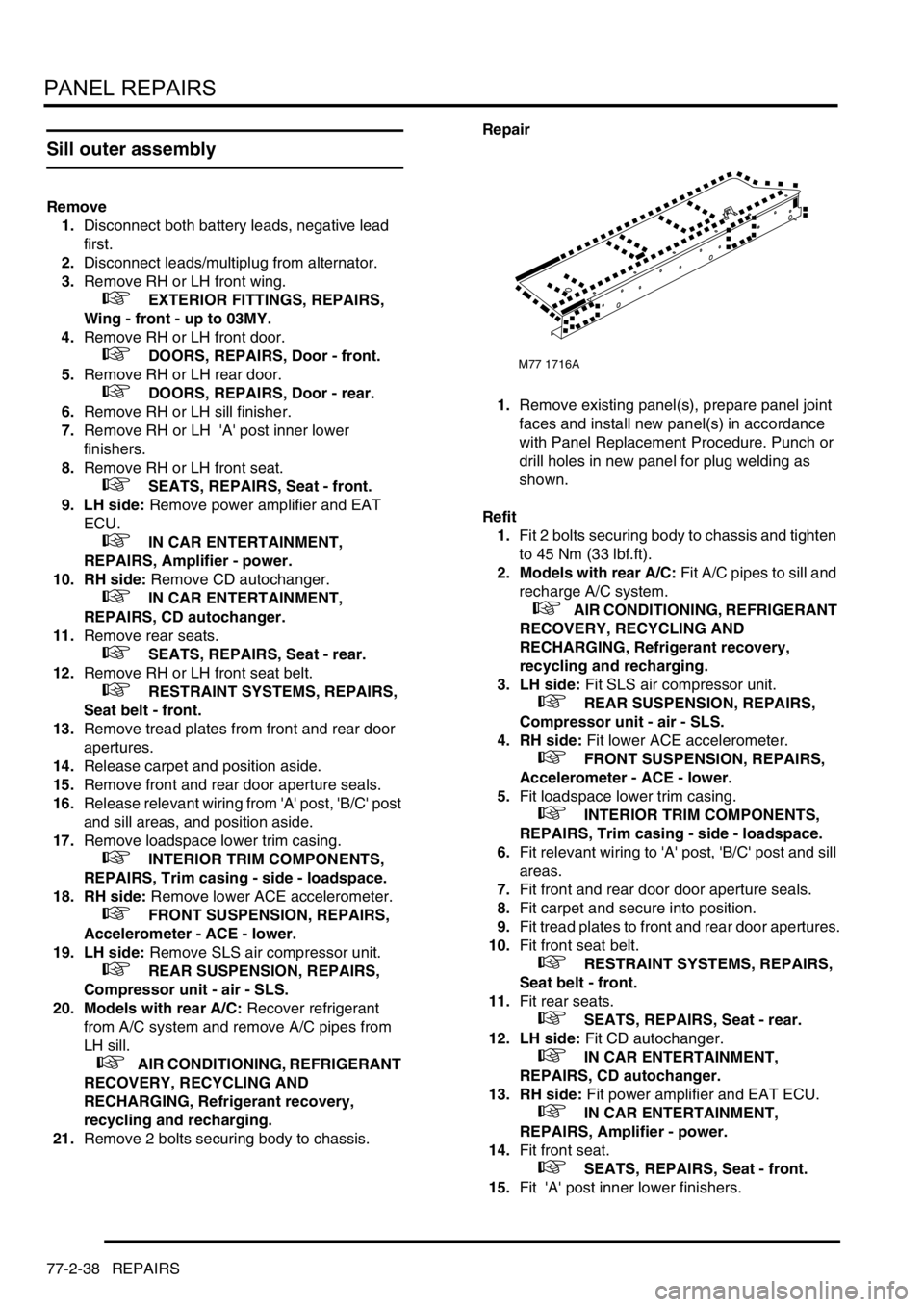
21.Remove 2 bolts securing body to chassis.Repair
1.Remove existing panel(s), prepare panel joint
faces and install new panel(s) in accordance
with Panel Replacement Procedure. Punch or
drill holes in new panel for plug welding as
shown.
Refit
1.Fit 2 bolts securing body to chassis and tighten
to 45 Nm (33 lbf.ft).
2. Models with rear A/C: Fit A/C pipes to sill and
recharge A/C system.
+ AIR CONDITIONING, REFRIGERANT
RECOVERY, RECYCLING AND
RECHARGING, Refrigerant recovery,
recycling and recharging.
3. LH side: Fit SLS air compressor unit.
+ REAR SUSPENSION, REPAIRS,
Compressor unit - air - SLS.
4. RH side: Fit lower ACE accelerometer.
+ FRONT SUSPENSION, REPAIRS,
Accelerometer - ACE - lower.
5.Fit loadspace lower trim casing.
+ INTERIOR TRIM COMPONENTS,
REPAIRS, Trim casing - side - loadspace.
6.Fit relevant wiring to 'A' post, 'B/C' post and sill
areas.
7.Fit front and rear door door aperture seals.
8.Fit carpet and secure into position.
9.Fit tread plates to front and rear door apertures.
10.Fit front seat belt.
+ RESTRAINT SYSTEMS, REPAIRS,
Seat belt - front.
11.Fit rear seats.
+ SEATS, REPAIRS, Seat - rear.
12. LH side: Fit CD autochanger.
+ IN CAR ENTERTAINMENT,
REPAIRS, CD autochanger.
13. RH side: Fit power amplifier and EAT ECU.
+ IN CAR ENTERTAINMENT,
REPAIRS, Amplifier - power.
14.Fit front seat.
+ SEATS, REPAIRS, Seat - front.
15.Fit 'A' post inner lower finishers.
M77 1716A
Page 1140 of 1529
CORROSION PREVENTION AND SEALING
CORROSION PREVENTION 77-4-7
The checks described above are intended to be visual only. It is not intended that the operator should remove trim
panels, finishers, rubbing strips or sound-deadening materials when checking the vehicle for corrosion and paint
damage.
With the vehicle on a lift, and using an inspection or spot lamp, visually check for the following:
lCorrosion damage and damaged paintwork, condition of underbody sealer on front and rear lower panels, sills
and wheel arches;
lDamage to underbody sealer. Corrosion in areas adjacent to suspension mountings and fuel tank fixings.
NOTE: The presence of small blisters in the underbody sealer is acceptable, providing they do not expose bare metal.
Pay special attention to signs of damage caused to panels or corrosion protection material by incorrect jack
positioning.
WARNING: It is essential to follow the correct jacking and lifting procedures.
With the vehicle lowered, visually check for evidence of damage and corrosion on all visible painted areas, in
particular the following:
lFront edge of bonnet;
lVisible flanges in engine compartment;
lLower body and door panels.
Rectify any bodywork damage or evidence of corrosion found during inspection as soon as is practicable, both to
minimise the extent of the damage and to ensure the long term effectiveness of the factory-applied corrosion
prevention treatment. Where the cost of rectification work is the owner's responsibility, the Dealer must advise the
owner and endorse the relevant documentation accordingly.
Where corrosion has become evident and is emanating from beneath a removable component (e.g. trim panel,
window glass, seat etc.), remove the component as required to permit effective rectification.
Underbody protection repairs
Whenever body repairs are carried out, ensure that full sealing and corrosion protection treatments are reinstated.
This applies both to the damaged areas and also to areas where protection has been indirectly impaired, as a result
either of accident damage or repair operations.
Remove corrosion protection from the damaged area before straightening or panel beating. This applies in particular
to panels coated with wax, PVC underbody sealer, sound deadening pads etc.
WARNING: DO NOT use oxy-acetylene gas equipment to remove corrosion prevention materials. Large
volumes of fumes and gases are liberated by these materials when they burn.
NOTE: Equipment for the removal of tough anti-corrosion sealers offers varying degrees of speed and effectiveness.
The compressed air-operated scraper (NOT an air chisel) offers a relatively quiet mechanical method using an
extremely rapid reciprocating action. Move the operating end of the tool along the work surface to remove the material.
The most common method of removal is by means of a hot air blower with integral scraper.
Another tool, and one of the most efficient methods, is the rapid-cutting 'hot knife'. This tool uses a wide blade and is
quick and versatile, able to be used easily in profiled sections where access is otherwise difficult.
Use the following procedure when repairing underbody coatings:
1Remove existing underbody coatings
2After panel repair, clean the affected area with a solvent wipe, and treat bare metal with an etch phosphate
material
3Re-prime the affected area
CAUTION: DO NOT, under any circumstances, apply underbody sealer directly to bare metal surfaces.
4Replace all heat-fusible plugs which have been disturbed. Where such plugs are not available use rubber
grommets of equivalent size, ensuring that they are embedded in sealer
5Mask off all mounting faces from which mechanical components, hoses and pipe clips, have been removed.
Underbody sealer must be applied before such components are refitted
6Brush sealer into all exposed seams
7Spray the affected area with an approved service underbody sealer
8Remove masking from component mounting faces, and touch-in where necessary. Allow adequate drying time
before applying underbody wax
Page 1142 of 1529
CORROSION PREVENTION AND SEALING
SEALING 77-4-9
SEALING
Body Sealing
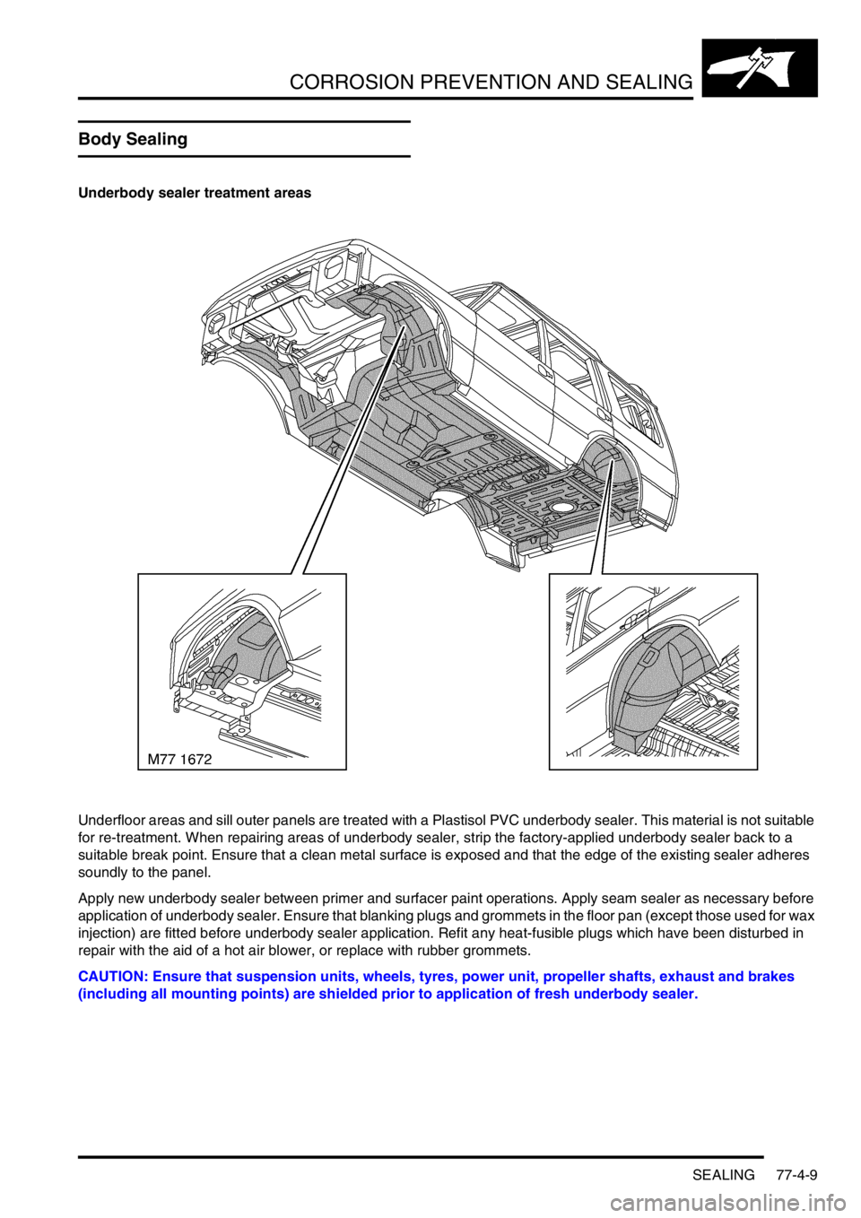
Underbody sealer treatment areas
Underfloor areas and sill outer panels are treated with a Plastisol PVC underbody sealer. This material is not suitable
for re-treatment. When repairing areas of underbody sealer, strip the factory-applied underbody sealer back to a
suitable break point. Ensure that a clean metal surface is exposed and that the edge of the existing sealer adheres
soundly to the panel.
Apply new underbody sealer between primer and surfacer paint operations. Apply seam sealer as necessary before
application of underbody sealer. Ensure that blanking plugs and grommets in the floor pan (except those used for wax
injection) are fitted before underbody sealer application. Refit any heat-fusible plugs which have been disturbed in
repair with the aid of a hot air blower, or replace with rubber grommets.
CAUTION: Ensure that suspension units, wheels, tyres, power unit, propeller shafts, exhaust and brakes
(including all mounting points) are shielded prior to application of fresh underbody sealer.