1999 LAND ROVER DISCOVERY belt
[x] Cancel search: beltPage 1108 of 1529
PANEL REPAIRS
REPAIRS 77-2-41
Refit
1.Fit side drip rail finisher.
2.Fit wiring to 'B/C' post and sill areas.
3.Fit front and rear door door aperture seal.
4.Position carpet and secure with fixings.
5.Fit tread plates to front and rear door apertures.
6.Fit head lining.
+ INTERIOR TRIM COMPONENTS,
REPAIRS, Headlining.
7.Fit rear seat.
+ SEATS, REPAIRS, Seat - rear.
8.Fit front seat belt.
+ RESTRAINT SYSTEMS, REPAIRS,
Seat belt - front.
9. LH side: Fit CD autochanger.
+ IN CAR ENTERTAINMENT,
REPAIRS, CD autochanger.
10. RH side: Fit power amplifier.
+ IN CAR ENTERTAINMENT,
REPAIRS, Amplifier - power.
11.Fit RH or LH front seat.
+ SEATS, REPAIRS, Seat - front.
12.Fit sill finisher.
13.Fit front door striker to B/C post, fit Torx bolts
and tighten to 26 Nm (19 lbf.ft).
14.Fit rear door.
+ DOORS, REPAIRS, Door - rear.
15.Connect leads/multiplug to alternator.
16.Connect battery leads, negative lead last.
Panel body side assembly
Remove
1.Disconnect both battery leads, negative lead
first.
2.Disconnect leads/multiplug from alternator.
3.Remove loadspace side trim casing.
+ INTERIOR TRIM COMPONENTS,
REPAIRS, Trim casing - side - loadspace.
4.Remove head lining rear trim finisher.
5.Remove rear head rests, if fitted.
6.Remove body side rear glass.
+ SCREENS, REPAIRS, Glass - body
side - rear.
7.Remove rear bumper assembly.
+ EXTERIOR FITTINGS, REPAIRS,
Bumper assembly - rear - up to 03MY.
8.Remove rear bumper finisher.
9.Remove rear wheel arch liner.
+ EXTERIOR FITTINGS, REPAIRS,
Liner - wheel arch - rear.
10.Remove mud flap.
11.Remove tread plate from rear door aperture.
12.Remove rear door aperture seal.
13.Remove rear door striker from 'D' post.
14.Remove 'D' post outer trim finisher.
15.Remove wheel arch trim finisher.
16.Remove side drip rail finisher.
17. RH side: Remove tail door.
18. LH side: Remove tail door striker and setting
block from 'E' post.
19.Remove tail door tread plate.
20.Remove loadspace carpet retainer.
21.Remove tail door aperture seal.
22.Remove tail lamp.
+ LIGHTING, REPAIRS, Lamp - tail.
23. RH side: Remove fuel filler flap.
24. RH side: Remove fuel filler tube.
+ FUEL DELIVERY SYSTEM - V8,
REPAIRS, Filler tube - fuel.
25.Remove aerial amplifier.
26.Remove relevant wiring from body side area.
Page 1110 of 1529
PANEL REPAIRS
REPAIRS 77-2-43
Body side inner rear assembly
In this procedure, the panel body side assembly is
replaced in conjunction with the body side inner rear
assembly.
Remove
1.Disconnect battery eath lead.
2.Disconnect leads/multiplug from alternator.
3.Remove panel body side assembly.
+ PANEL REPAIRS, REPAIRS, Panel
body side assembly.
4.Remove RH or LH rear seat.
+ SEATS, REPAIRS, Seat - rear.
5.Remove loadspace carpet.
+ INTERIOR TRIM COMPONENTS,
REPAIRS, Carpet - loadspace.
6.Remove rear side seat belt.
+ RESTRAINT SYSTEMS, REPAIRS,
Seat belt - rear - side.
7.Remove third row seat belt.
+ RESTRAINT SYSTEMS, REPAIRS,
Seat belts - third row.
8.Remove fuel tank.
+ FUEL DELIVERY SYSTEM - V8,
REPAIRS, Tank - fuel.
+ FUEL DELIVERY SYSTEM - Td5,
REPAIRS, Tank - fuel.
9.Remove fuel filler tube.
+ FUEL DELIVERY SYSTEM - V8,
REPAIRS, Filler tube - fuel.
10. RH side: Remove fuel flap release solenoid.
+ FUEL DELIVERY SYSTEM - Td5,
REPAIRS, Solenoid - fuel filler flap release.
+ FUEL DELIVERY SYSTEM - V8,
REPAIRS, Solenoid - fuel filler flap release.
11. RH side: Remove air extractor vent.
12.Remove relevant wiring.Repair
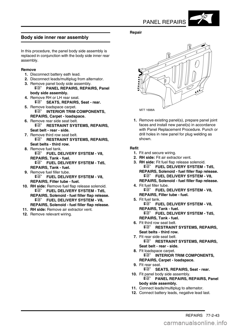
1.Remove existing panel(s), prepare panel joint
faces and install new panel(s) in accordance
with Panel Replacement Procedure. Punch or
drill holes in new panel for plug welding as
shown.
Refit
1.Fit and secure wiring.
2. RH side: Fit air extractor vent.
3. RH side: Fit fuel flap release solenoid.
+ FUEL DELIVERY SYSTEM - Td5,
REPAIRS, Solenoid - fuel filler flap release.
+ FUEL DELIVERY SYSTEM - V8,
REPAIRS, Solenoid - fuel filler flap release.
4.Fit fuel filler tube.
+ FUEL DELIVERY SYSTEM - V8,
REPAIRS, Filler tube - fuel.
5.Fit fuel tank.
+ FUEL DELIVERY SYSTEM - V8,
REPAIRS, Tank - fuel.
+ FUEL DELIVERY SYSTEM - Td5,
REPAIRS, Tank - fuel.
6.Fit third row seat belt.
+ RESTRAINT SYSTEMS, REPAIRS,
Seat belts - third row.
7.Fit rear side seat belt.
+ RESTRAINT SYSTEMS, REPAIRS,
Seat belt - rear - side.
8.Fit loadspace carpet.
+ INTERIOR TRIM COMPONENTS,
REPAIRS, Carpet - loadspace.
9.Fit rear seat.
+ SEATS, REPAIRS, Seat - rear.
10.Fit panel body side assembly.
+ PANEL REPAIRS, REPAIRS, Panel
body side assembly.
11.Connect leads/multiplug to alternator.
12.Connect battery leads, negative lead last.
M77 1698A
Page 1113 of 1529
PANEL REPAIRS
77-2-46 REPAIRS
'E' post assembly
In this procedure, the panel body side assembly and
tail door are replaced in conjunction with the 'E' post
assembly. If required the 'E' post closing assembly
can also be replaced.
Remove
1.Disconnect both battery leads, negative lead
first.
2.Disconnect leads/multiplug from alternator.
3.Remove panel body side assembly.
+ PANEL REPAIRS, REPAIRS, Panel
body side assembly.
4.Remove rear seats.
+ SEATS, REPAIRS, Seat - rear.
5.Remove loadspace carpet.
+ INTERIOR TRIM COMPONENTS,
REPAIRS, Carpet - loadspace.
6.Remove third row seat belts.
+ RESTRAINT SYSTEMS, REPAIRS,
Seat belts - third row.
7.Remove relevant wiring.
8.Remove rear drip rail finisher.
Repair
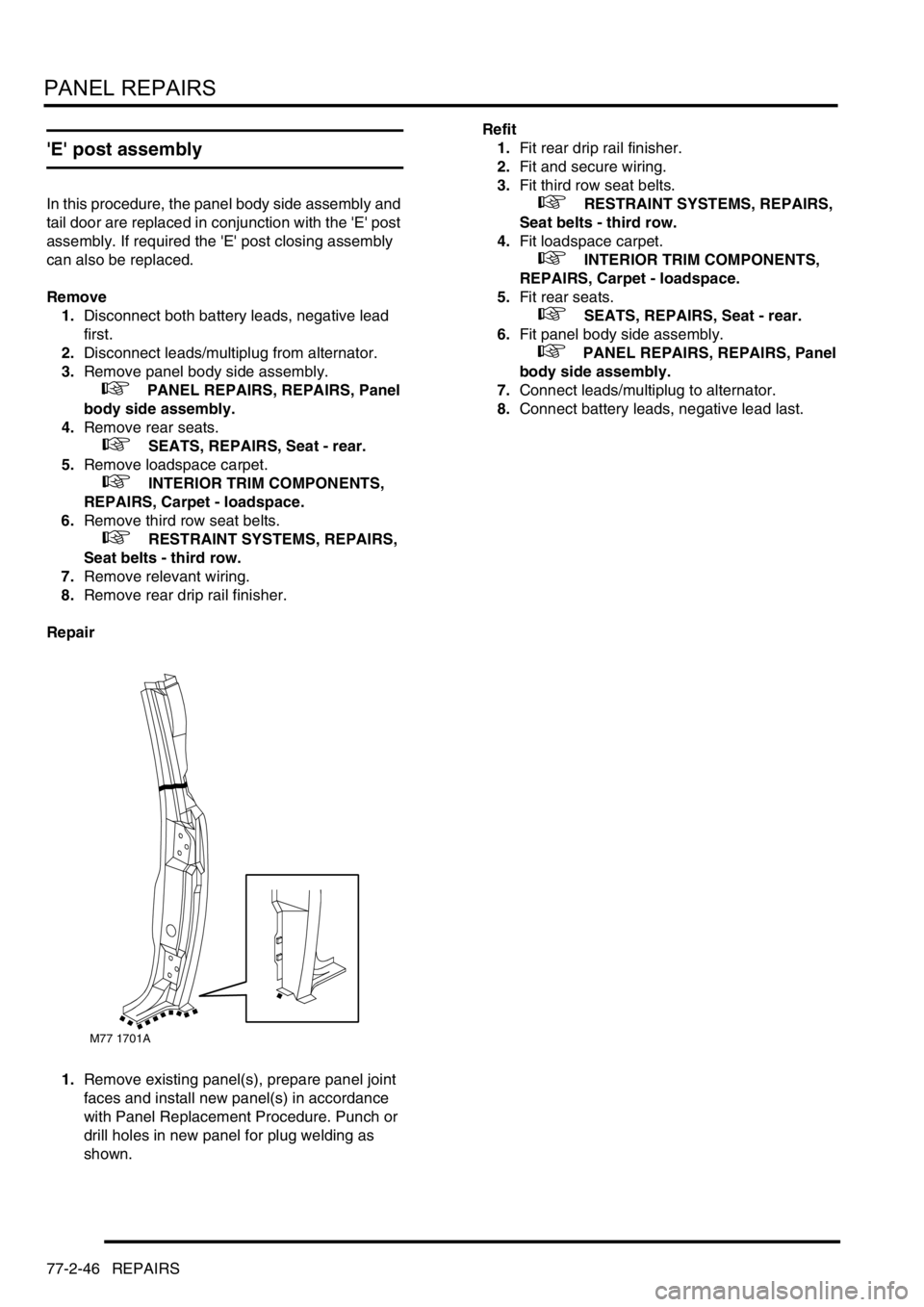
1.Remove existing panel(s), prepare panel joint
faces and install new panel(s) in accordance
with Panel Replacement Procedure. Punch or
drill holes in new panel for plug welding as
shown.Refit
1.Fit rear drip rail finisher.
2.Fit and secure wiring.
3.Fit third row seat belts.
+ RESTRAINT SYSTEMS, REPAIRS,
Seat belts - third row.
4.Fit loadspace carpet.
+ INTERIOR TRIM COMPONENTS,
REPAIRS, Carpet - loadspace.
5.Fit rear seats.
+ SEATS, REPAIRS, Seat - rear.
6.Fit panel body side assembly.
+ PANEL REPAIRS, REPAIRS, Panel
body side assembly.
7.Connect leads/multiplug to alternator.
8.Connect battery leads, negative lead last.
M77 1701A
Page 1141 of 1529
CORROSION PREVENTION AND SEALING
77-4-8 CORROSION PREVENTION
After refitting mechanical components, including hoses and pipes and other fixtures, mask off the brake discs and
apply a coat of approved underbody wax.
NOTE: Where repairs include the application of finish paint coats in the areas requiring underbody wax, carry out paint
operations before applying wax.
Cavity wax injection
Areas treated with cavity wax are shown in the previous figures. After repairs, always re-treat these areas with an
approved cavity wax. In addition, treat all interior surfaces which have been disturbed during repairs whether they
have been treated in production or not. This includes all box members, cavities and door interiors. It is permissible to
drill extra holes for access where necessary, provided these are not positioned in load-bearing members. Ensure that
such holes are treated with a suitable zinc rich primer, brushed with wax and then sealed with a rubber grommet.
Before wax injection, ensure that the cavity to be treated is free from any contamination or foreign matter. Where
necessary, clear out any debris using compressed air.
Ensure that cavity wax is applied AFTER the final paint process and BEFORE refitting any trim components.
During application, ensure that the wax covers all flange and seam areas and that it is adequately applied to all
repaired areas of both new and existing panels.
It should be noted that new panel assemblies and complete body shells are supplied without wax injection treatment.
Ensure that such treatment is carried out after repairs.
Effective cavity wax protection is vital. Always observe the following points:
lComplete all paint refinish operations before wax application;
lClean body panel areas and blow-clean cavities if necessary, before treatment;
lMaintain a temperature of 18° C (64° F) during application and drying;
lCheck the spray pattern of injection equipment;
lMask off all areas not to be wax coated and which could be contaminated by wax overspray;
lRemove body fixings, such as seat belt retractors, if contamination is at all likely;
lMove door glasses to fully closed position before treating door interiors;
lTreat body areas normally covered by trim before refitting items;
lCheck that body and door drain holes are clear after the protective wax has dried;
lKeep all equipment clean, especially wax injection nozzles.
Underbody wax
The underbody wax must be reinstated following all repairs affecting floor panels. The wax is applied over paints and
underbody sealers.
Remove old underbody wax completely from a zone extending at least 200 mm (7.874 in) beyond the area where new
underbody sealer is to be applied.
Engine bay wax
Reinstate all protective engine bay wax disturbed during repairs using an approved material.
Where repairs have involved replacement of engine bay panels, treat the entire engine compartment including all
components, clips and other fixtures with an approved underbonnet lacquer or wax.
+ BODY SEALING MATERIALS, MATERIALS AND APPLICATIONS, Approved materials.
Page 1194 of 1529
AIR CONDITIONING
DESCRIPTION AND OPERATION 82-5
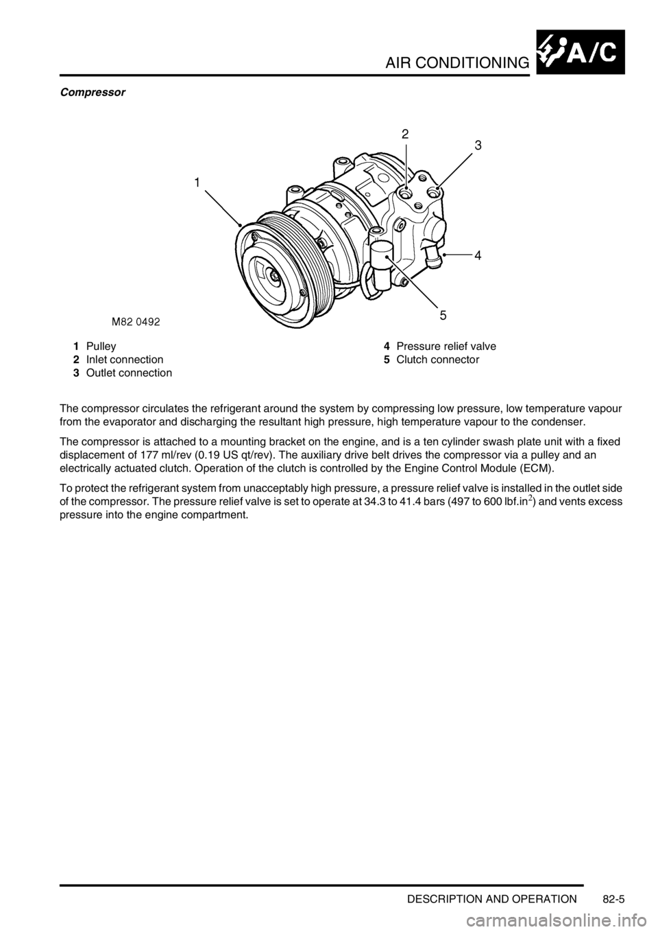
Compressor
1Pulley
2Inlet connection
3Outlet connection4Pressure relief valve
5Clutch connector
The compressor circulates the refrigerant around the system by compressing low pressure, low temperature vapour
from the evaporator and discharging the resultant high pressure, high temperature vapour to the condenser.
The compressor is attached to a mounting bracket on the engine, and is a ten cylinder swash plate unit with a fixed
displacement of 177 ml/rev (0.19 US qt/rev). The auxiliary drive belt drives the compressor via a pulley and an
electrically actuated clutch. Operation of the clutch is controlled by the Engine Control Module (ECM).
To protect the refrigerant system from unacceptably high pressure, a pressure relief valve is installed in the outlet side
of the compressor. The pressure relief valve is set to operate at 34.3 to 41.4 bars (497 to 600 lbf.in
2) and vents excess
pressure into the engine compartment.
Page 1218 of 1529
AIR CONDITIONING
REPAIRS 82-29
REPAIRS
Compressor - diesel
$% 82.10.20
Remove
1.Remove engine acoustic cover.
2.Depressurise air conditioning system.
+ AIR CONDITIONING, REFRIGERANT
RECOVERY, RECYCLING AND
RECHARGING, Refrigerant recovery,
recycling and recharging.
3.Remove auxiliary drive belt.
+ CHARGING AND STARTING,
REPAIRS, Belt - auxiliary drive.
4.Drain cooling system.
+ COOLING SYSTEM - Td5,
ADJUSTMENTS, Drain and refill.
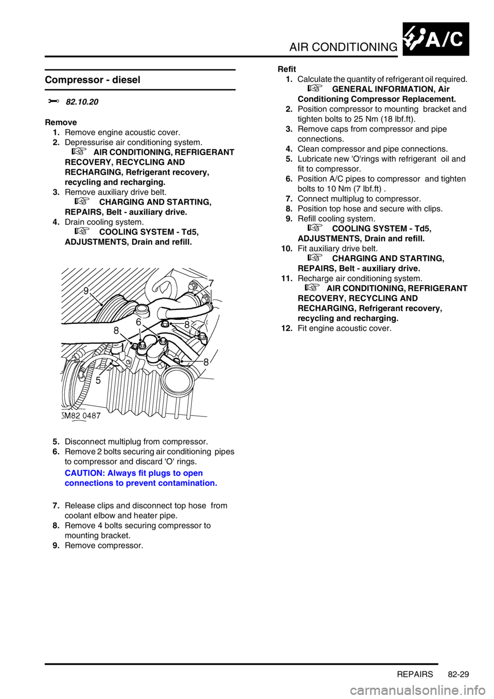
5.Disconnect multiplug from compressor.
6.Remove 2 bolts securing air conditioning pipes
to compressor and discard 'O' rings.
CAUTION: Always fit plugs to open
connections to prevent contamination.
7.Release clips and disconnect top hose from
coolant elbow and heater pipe.
8.Remove 4 bolts securing compressor to
mounting bracket.
9.Remove compressor.Refit
1.Calculate the quantity of refrigerant oil required.
+ GENERAL INFORMATION, Air
Conditioning Compressor Replacement.
2.Position compressor to mounting bracket and
tighten bolts to 25 Nm (18 lbf.ft).
3.Remove caps from compressor and pipe
connections.
4.Clean compressor and pipe connections.
5.Lubricate new 'O'rings with refrigerant oil and
fit to compressor.
6.Position A/C pipes to compressor and tighten
bolts to 10 Nm (7 lbf.ft) .
7.Connect multiplug to compressor.
8.Position top hose and secure with clips.
9.Refill cooling system.
+ COOLING SYSTEM - Td5,
ADJUSTMENTS, Drain and refill.
10.Fit auxiliary drive belt.
+ CHARGING AND STARTING,
REPAIRS, Belt - auxiliary drive.
11.Recharge air conditioning system.
+ AIR CONDITIONING, REFRIGERANT
RECOVERY, RECYCLING AND
RECHARGING, Refrigerant recovery,
recycling and recharging.
12.Fit engine acoustic cover.
Page 1219 of 1529

AIR CONDITIONING
82-30REPAIRS
Compressor - V8
$% 82.10.20
Remove
1.Depressurise air conditioning system.
+ AIR CONDITIONING, REFRIGERANT
RECOVERY, RECYCLING AND
RECHARGING, Refrigerant recovery,
recycling and recharging.
2.Remove auxiliary drive belt.
+ CHARGING AND STARTING,
REPAIRS, Belt - auxiliary drive.
3.Disconnect multiplug from compressor.
4.Remove 2 bolts securing air conditioning pipes
to compressor and discard 'O' rings.
CAUTION: Always fit plugs to open
connections to prevent contamination.
5.Remove 4 bolts securing compressor to
mounting bracket.
6.Remove compressor.Refit
1.Calculate the quantity of refrigerant oil required.
+ GENERAL INFORMATION, Air
Conditioning Compressor Replacement.
2.Clean compressor dowels and dowel holes.
3.Position compressor to mounting bracket and
tighten bolts to 25 Nm (18 lbf.ft).
4.Remove caps from compressor and pipe
connections.
5.Clean compressor and pipe connections.
6.Lubricate new 'O' rings with refrigerant oil and
fit to compressor.
7.Position A/C pipes to compressor and tighten
bolts to 10 Nm (7 lbf.ft).
8.Connect multiplug to compressor.
9.Fit auxiliary drive belt.
+ CHARGING AND STARTING,
REPAIRS, Belt - auxiliary drive.
10.Recharge air conditioning system.
+ AIR CONDITIONING, REFRIGERANT
RECOVERY, RECYCLING AND
RECHARGING, Refrigerant recovery,
recycling and recharging.
Page 1266 of 1529
CHARGING AND STARTING
REPAIRS 86-1-1
CHARGING AND STARTING REPAIRS
Alternator - diesel
$% 86.10.02
Remove
1.Remove auxiliary drive belt.
+ CHARGING AND STARTING,
REPAIRS, Belt - auxiliary drive.
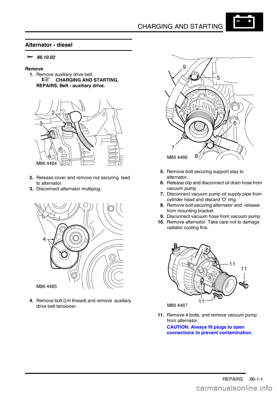
2.Release cover and remove nut securing lead
to alternator.
3.Disconnect alternator multiplug.
4.Remove bolt (LH thread) and remove auxiliary
drive belt tensioner. 5.Remove bolt securing support stay to
alternator.
6.Release clip and disconnect oil drain hose from
vacuum pump.
7.Disconnect vacuum pump oil supply pipe from
cylinder head and discard 'O' ring.
8.Remove bolt securing alternator and release
from mounting bracket.
9.Disconnect vacuum hose from vacuum pump.
10.Remove alternator. Take care not to damage
radiator cooling fins.
11.Remove 4 bolts, and remove vacuum pump
from alternator.
CAUTION: Always fit plugs to open
connections to prevent contamination.