1999 LAND ROVER DISCOVERY belt
[x] Cancel search: beltPage 1267 of 1529

CHARGING AND STARTING
86-1-2 REPAIRS
Refit
1.Clean mating faces of alternator and vacuum
pump.
2.Fit vacuum pump to alternator and tighten
bolts to 8 Nm (6 lbf.ft).
3.Position alternator to engine and connect
multiplug.
4.Connect vacuum hose and oil drain hose to
vacuum pump and secure clips.
5.With assistance align alternator to mounting
bracket and fit but do not tighten bolt.
6.Fit bolt securing support stay to alternator and
tighten to 25 Nm (18 lbf.ft) .
7.Tighten bolt securing alternator to mounting
bracket to 45 Nm (33 lbf.ft).
8.Using new 'O' ring, connect oil supply pipe to
cylinder head and tighten to 10 Nm (7 lbf.ft).
9.Connect lead to alternator and tighten nut to 6
Nm (4.4 lbf.ft).
10.Fit auxiliary drive belt tensioner and tighten bolt
to 50 Nm (37 lbf.ft).
11.Fit auxiliary drive belt.
+ CHARGING AND STARTING,
REPAIRS, Belt - auxiliary drive.
Page 1268 of 1529

CHARGING AND STARTING
REPAIRS 86-1-3
Alternator - V8
$% 86.10.02
Remove
1.Remove auxiliary drive belt.
+ CHARGING AND STARTING,
REPAIRS, Belt - auxiliary drive.
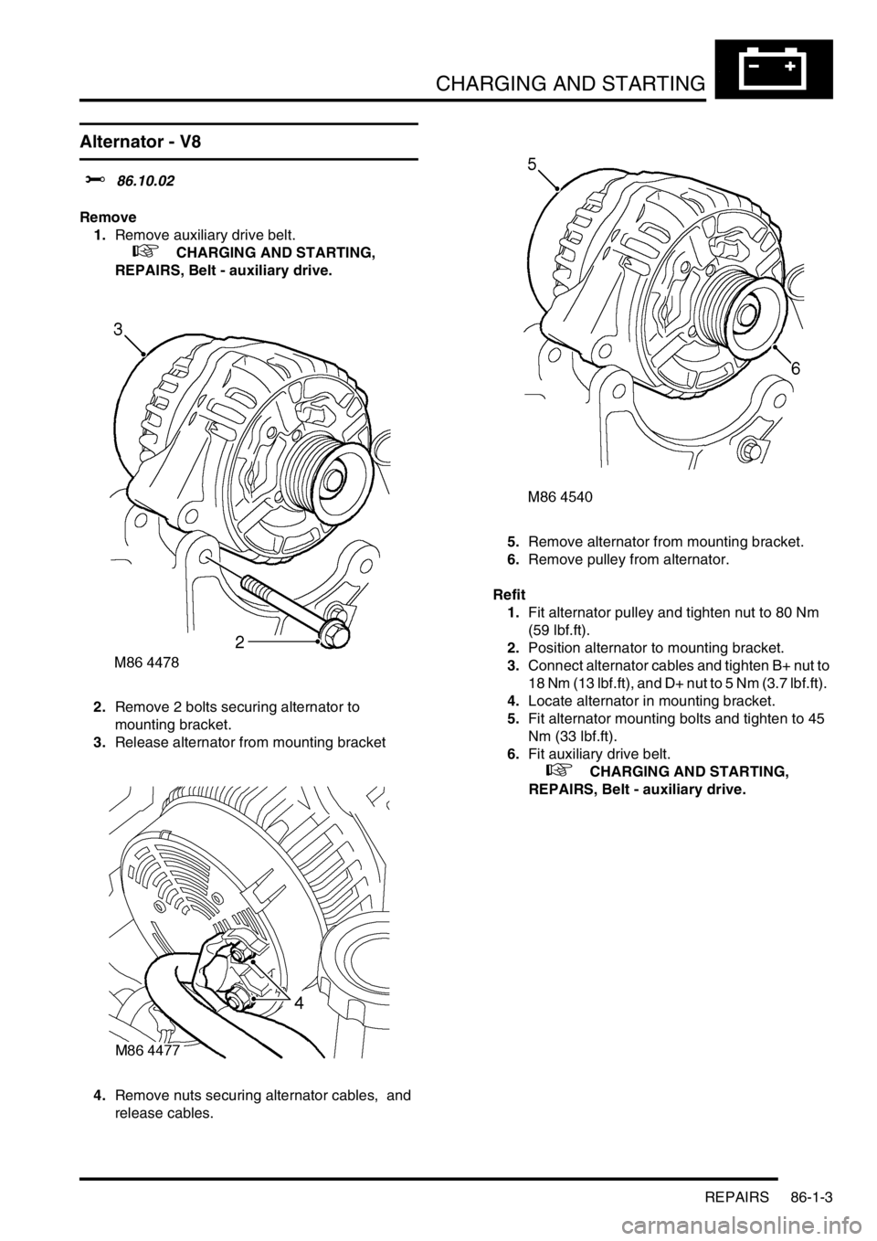
2.Remove 2 bolts securing alternator to
mounting bracket.
3.Release alternator from mounting bracket
4.Remove nuts securing alternator cables, and
release cables. 5.Remove alternator from mounting bracket.
6.Remove pulley from alternator.
Refit
1.Fit alternator pulley and tighten nut to 80 Nm
(59 lbf.ft).
2.Position alternator to mounting bracket.
3.Connect alternator cables and tighten B+ nut to
18 Nm (13 lbf.ft), and D+ nut to 5 Nm (3.7 lbf.ft).
4.Locate alternator in mounting bracket.
5.Fit alternator mounting bolts and tighten to 45
Nm (33 lbf.ft).
6.Fit auxiliary drive belt.
+ CHARGING AND STARTING,
REPAIRS, Belt - auxiliary drive.
Page 1269 of 1529

CHARGING AND STARTING
86-1-4 REPAIRS
Belt - auxiliary drive
$% 86.10.03
Remove
1.Remove viscous fan:
l
+ COOLING SYSTEM - V8,
REPAIRS, Fan - viscous.
l
+ COOLING SYSTEM - Td5,
REPAIRS, Fan - viscous.
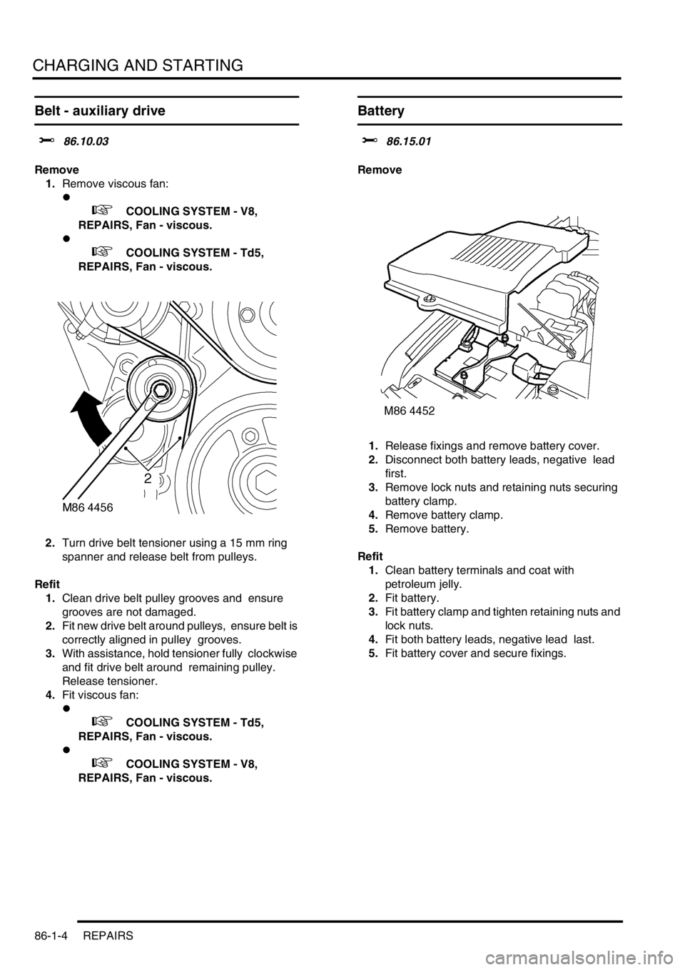
2.Turn drive belt tensioner using a 15 mm ring
spanner and release belt from pulleys.
Refit
1.Clean drive belt pulley grooves and ensure
grooves are not damaged.
2.Fit new drive belt around pulleys, ensure belt is
correctly aligned in pulley grooves.
3.With assistance, hold tensioner fully clockwise
and fit drive belt around remaining pulley.
Release tensioner.
4.Fit viscous fan:
l
+ COOLING SYSTEM - Td5,
REPAIRS, Fan - viscous.
l
+ COOLING SYSTEM - V8,
REPAIRS, Fan - viscous.
Battery
$% 86.15.01
Remove
1.Release fixings and remove battery cover.
2.Disconnect both battery leads, negative lead
first.
3.Remove lock nuts and retaining nuts securing
battery clamp.
4.Remove battery clamp.
5.Remove battery.
Refit
1.Clean battery terminals and coat with
petroleum jelly.
2.Fit battery.
3.Fit battery clamp and tighten retaining nuts and
lock nuts.
4.Fit both battery leads, negative lead last.
5.Fit battery cover and secure fixings.
Page 1299 of 1529

BODY CONTROL UNIT
86-3-12 DESCRIPTION AND OPERATION
Seatbelt warning lamp Timed The warning lamp is on for 6 seconds after the ignition is turned on.
Buckle The warning lamp is on for 6 seconds after ignition is turned on or until
the buckle is fastened.
Ignition II If the buckle is unfastened when the ignition is turned on then the
warning lamp comes on for 6 seconds.
Disable The warning lamp is not used.
Seatbelt audible warning Timed The audible warning is on for 6 seconds after the ignition is turned on.
Buckle The audible warning is on for 6 seconds after the ignition is turned on
or until the buckle is fastened.
Ignition II If the buckle is unfastened when the ignition is turned on then the
audible warning is on for 6 seconds.
Disable The audible warning is not used.
Bulb failure warning Disabled Direction indicator bulb failure detection is disabled.
Enabled Direction indicator bulb failure detection is enabled.
Superlocking None Superlocking is not available.
Double The vehicle will superlock on a double press of the remote transmitter
or double key turn.
Single The vehicle will superlock on a single press of the remote transmitter
or a single key turn.
No key The vehicle will superlock on a single press of the remote transmitter
but not with the key.
Door unlocking Not SPE The SPE (Single Point Entry) function is not used. All doors unlock on
a remote transmitter press.
SPE Only the driver's door unlocks on the first remote transmitter press, all
other doors on the second press.
Alarm disarming Always Operation of the key in the driver's door always disarms the vehicle.
Key only Operation of the key in the driver's door only disarms the vehicle if it
was locked with the key.
Key never The security system is not disarmed by the key (except for EKA).
Inertia switch No hazards Operation of the inertia switch does not operate the hazard warning
lamps.
Hazards Operation of the inertia switch operates the hazard warning lamps.
Speed locking Disabled Speed related locking is disabled.
Enabled Speed related locking is enabled. The door locks are disabled when
the vehicle is moving.
Volumetric sensing Disabled Volumetric sensing is disabled.
Enabled Volumetric sensing is enabled.
Alarm Disabled The vehicle is not fitted with a security system.
Enabled The vehicle is fitted with a security system.
Passive immobilisation Disabled Passive immobilisation is disabled.
Enabled Passive immobilisation is enabled.
Hazard warning lamps Disabled The hazard warning lamps do not flash on security system arm,
disarm or trigger.
Enabled The hazard warning lamps flash on security system trigger only.
All The hazards flash on security system arm, disarm and trigger.
Mislocking audible
warningDisabled Mislock audible warnings are disabled.
Enabled Mislock audible warnings are enabled.
Alarm sounder Alarm Audible warnings are given by the security system sounder only.
Both Audible warnings are given by both the security system sounder and
the vehicle horn.
Vehicle Audible warnings are given by the vehicle horn only.
BBUS Audible warnings are given by the security system sounder, vehicle
horn and BBUS.
Disabled Audible warnings are not given. Function Option Details
Page 1305 of 1529

BODY CONTROL UNIT
86-3-18 DESCRIPTION AND OPERATION
Audible warnings
The BCU can request the instrument pack to generate an audible warning in response to conditions it has detected
and which need to be drawn to the driver's attention. One of six different audible warnings can be requested by the
BCU.
Sound request number Sound functions Priority (1 = lowest, 6 = highest)
0Off 1
1 Seat belt warning 6
2Key-in warning 3
3 SLABS/ HDC warning 4
4 Transfer box in neutral warning 5
5 Lights on warning 2
Page 1320 of 1529

BODY CONTROL UNIT
DESCRIPTION AND OPERATION 86-3-33
In the event of a communications link failure occurring while the transfer box enable is on, the output will be switched
off.
Gear position switch
On automatic gearbox models, the BCU provides an output which supplies power to the automatic gearbox gear
position switch. The BCU checks for the following inputs before it supplies power:
lIgnition on.
lAuxiliary.
When the ignition is on, the feed to the gear position switch is on. When the ignition is off and auxiliary is off for more
than 30 seconds, feed to the gear position switch is off.
+ AUTOMATIC GEARBOX - ZF4HP22 - 24, DESCRIPTION AND OPERATION, Description.
Fuel flap release
The fuel flap release solenoid only operates when the ignition switch is switched off, the anti-theft system is not
activated and the fuel flap release switch is pressed. If the BCU detects that these conditions have been satisfied, it
provides a path to earth for the fuel flap solenoid, so allowing the fuel flap to be opened.
To decide the correct conditions for providing a fuel flap enable output, the BCU checks the following input conditions:
lIgnition state.
lPerimetric alarm state.
If the battery state is not normal, the electric fuel flap enable is switched off.
Audible warnings
The BCU can request the instrument pack to generate an audible warning in response to logic conditions which have
been detected by the BCU and which need to be drawn to the driver's attention.
+ INSTRUMENTS, DESCRIPTION AND OPERATION, Description.
Seat belt warning
The BCU can be programmed to include seat belt warning using one of four options:
lOption 1 – warning on for 6 seconds.
lOption 2 – warning on for 6 seconds or until the seat belt is fastened.
lOption 3 – warning on for 6 seconds unless the seat belt is fastened.
lOption 4 – no warning.
The BCU checks the status of the following inputs:
lIgnition on.
lSeat belt fastened.
Depending on the logic conditions of the inputs, the BCU provides the following outputs:
lAudible warning No.1 requested.
lSeat belt not fastened warning on instrument pack (via datalink to the instrument pack).
When programmed for option 1 operation, audible warning No. 1 is requested when the ignition switch is turned from
off to position II. The audible warning remains active for 6 seconds and a warning lamp on the instrument pack is
illuminated for the same duration.
When programmed for option 2 operation, audible warning No. 1 is requested when the ignition switch is turned from
off to position II. The audible warning remains active for 6 seconds or until the seat belt fastened signal is on and a
warning lamp on the instrument pack is illuminated for the same duration.
When programmed for option 3 operation, audible warning No. 1 is requested when the ignition switch is turned from
off to position II. The audible warning remains active for 6 seconds if the seat belt fastened signal is off; a warning
lamp on the instrument pack is illuminated for the same duration.
In the event of a communications link failure occurring, the audible and visual warning requests are not sent to the
instrument pack.
Page 1484 of 1529

INSTRUMENTS
DESCRIPTION AND OPERATION 88-1
INS TRUMENTS DESCRIPTION AND OPERAT ION
Instrument pack
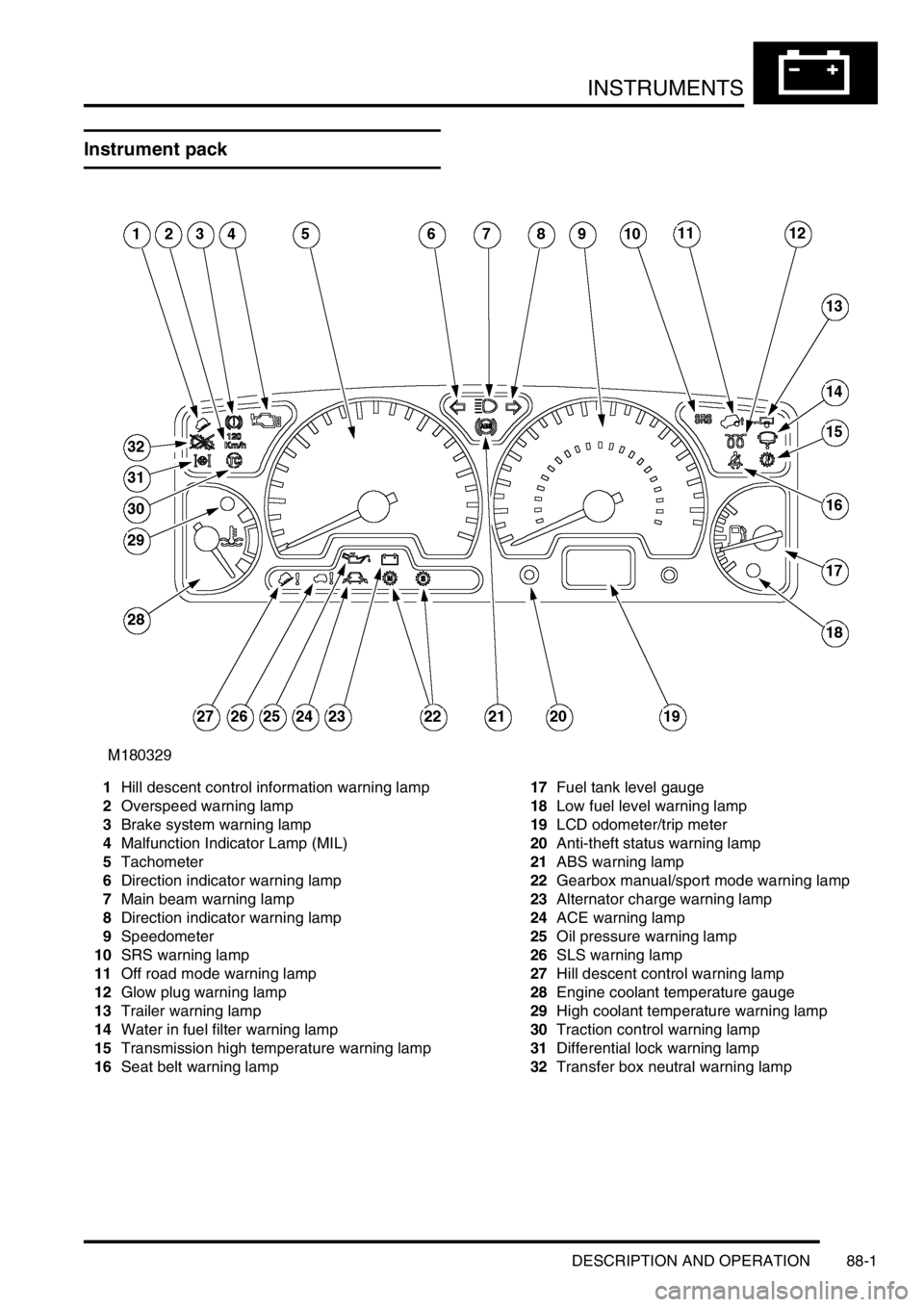
1Hill descent control information warning lamp
2Overspeed warning lamp
3Brake system warning lamp
4Malfunction Indicator Lamp (MIL)
5Tachometer
6Direction indicator warning lamp
7Main beam warning lamp
8Direction indicator warning lamp
9Speedometer
10SRS warning lamp
11Off road mode warning lamp
12Glow plug warning lamp
13Trailer warning lamp
14Water in fuel filter warning lamp
15Transmission high temperature warning lamp
16Seat belt warning lamp17Fuel tank level gauge
18Low fuel level warning lamp
19LCD odometer/trip meter
20Anti-theft status warning lamp
21ABS warning lamp
22Gearbox manual/sport mode warning lamp
23Alternator charge warning lamp
24ACE warning lamp
25Oil pressure warning lamp
26SLS warning lamp
27Hill descent control warning lamp
28Engine coolant temperature gauge
29High coolant temperature warning lamp
30Traction control warning lamp
31Differential lock warning lamp
32Transfer box neutral warning lamp
Page 1489 of 1529

INSTRUMENTS
88-6 DESCRIPTION AND OPERATION
The third warning lamp pack is located in the top right-hand side of the instrument pack and contains the following
warning lamps:
lSRS warning lamp.
lSLS off road mode warning lamp.
lTrailer warning lamp.
lGlow plug warning lamp.
lWater in fuel filter warning lamp.
lSeat belt warning lamp.
lTransmission high temperature warning lamp.
The fourth warning lamp pack is located underneath the tachometer of the instrument pack contains the following
warning lamps:
lOil pressure warning lamp.
lAlternator charge warning lamp.
lHDC fault warning lamp.
lSelf Levelling Suspension (SLS) warning lamp.
lActive Cornering Enhancement (ACE) warning lamp.
lGearbox manual/sport mode warning lamps.
The serial communication link is used to allow information to travel to and from the instrument pack, and it provides
the ability to configure the instrument pack to a specific market. It also allows the instrument pack to be controlled by
TestBook for diagnostics.
There are five market specific variants of the instrument pack:
lUnited Kingdom (UK).
lNorth American Specification (NAS).
lCanada.
lAustralia.
lRest Of the World (ROW), Gulf and Japan.
The main difference between the five markets is that the speedometer will indicate road speed in mph as major figures
and km/h as minor figures, km/h as major figures and mph as minor figures or km/h only.
When TestBook is used to diagnose the instrument pack it demands each of the dials and warning lamps to operate
in-turn so a visual check of their operation can be made.
CAUTION: The instrument pack must not be stored on its face side at any time. This is because the dials have
damping fluid within them to ensure smooth operation of the dials' indicator needles. This fluid will leak out.
Speedometer
The speedometer informs the driver of the current vehicle road speed. It has a Liquid Crystal Display (LCD) to show
odometer, trip meter and, on automatic gearbox models, the selected gear. The speedometer will not show speeds
of less than 1.5 mph (2.5 km/h).
There are three different market configurations:
lNAS and UK = mph as major figures km/h as minor figures.
lCanada = km/h as major figures mph as minor figures.
lROW and Australia = km/h only.
The Self Levelling and Anti-Lock Brake System (SLABS) ECU provides the signal input for the road speed. The signal
is at 8000 pulses per mile (1.6 kilometres).