Page 1029 of 1529

SEATS
76-5-32 REPAIRS
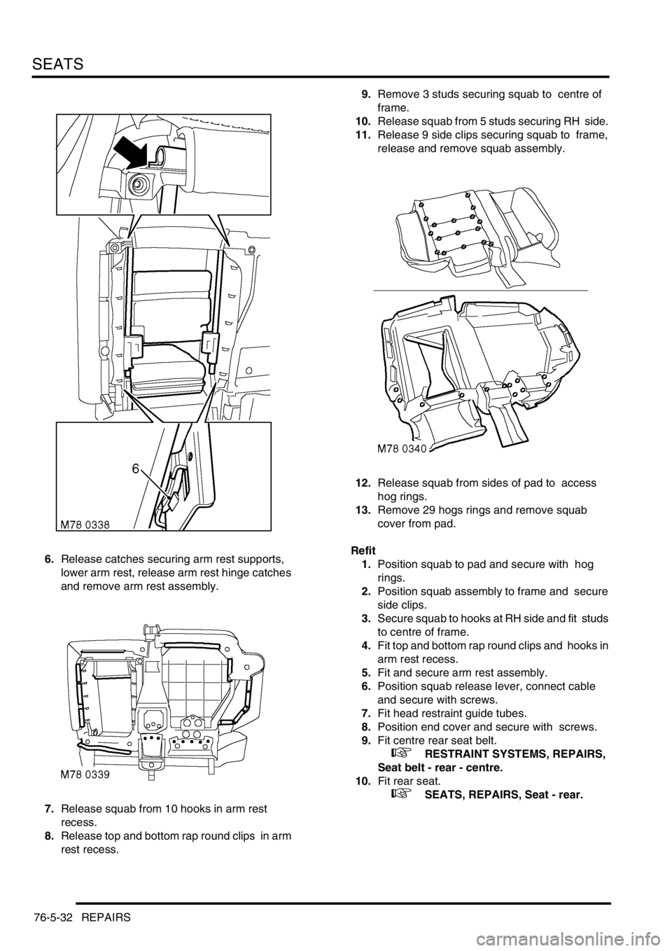
6.Release catches securing arm rest supports,
lower arm rest, release arm rest hinge catches
and remove arm rest assembly.
7.Release squab from 10 hooks in arm rest
recess.
8.Release top and bottom rap round clips in arm
rest recess. 9.Remove 3 studs securing squab to centre of
frame.
10.Release squab from 5 studs securing RH side.
11.Release 9 side clips securing squab to frame,
release and remove squab assembly.
12.Release squab from sides of pad to access
hog rings.
13.Remove 29 hogs rings and remove squab
cover from pad.
Refit
1.Position squab to pad and secure with hog
rings.
2.Position squab assembly to frame and secure
side clips.
3.Secure squab to hooks at RH side and fit studs
to centre of frame.
4.Fit top and bottom rap round clips and hooks in
arm rest recess.
5.Fit and secure arm rest assembly.
6.Position squab release lever, connect cable
and secure with screws.
7.Fit head restraint guide tubes.
8.Position end cover and secure with screws.
9.Fit centre rear seat belt.
+ RESTRAINT SYSTEMS, REPAIRS,
Seat belt - rear - centre.
10.Fit rear seat.
+ SEATS, REPAIRS, Seat - rear.
Page 1062 of 1529
CHASSIS AND BODY DIMENSIONS
BODY DIMENSIONS 77-1-11
Internal information
I.D Description Length
A Distance between seat belt anchorage top fixing and
seat belt reel lower fixing1814.5 (71.437)
B Distance between seat belt anchorage lower fixings on
wheel arch inner1430.2 (56.307)
M77 1760
A
B
Page 1080 of 1529

PANEL REPAIRS
PROCEDURES 77-2-13
PROCEDURES
General welding precautions
General
For ease of reference, the diagrams on the following pages show only the type of weld used in repair where it varies
from that used in production.
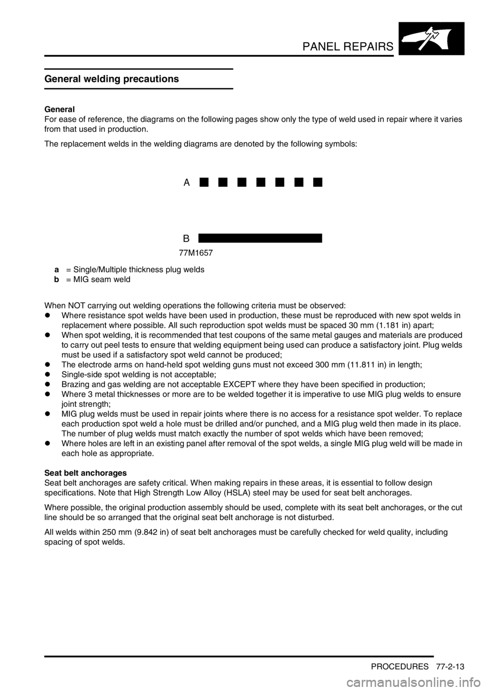
The replacement welds in the welding diagrams are denoted by the following symbols:
a = Single/Multiple thickness plug welds
b = MIG seam weld
When NOT carrying out welding operations the following criteria must be observed:
lWhere resistance spot welds have been used in production, these must be reproduced with new spot welds in
replacement where possible. All such reproduction spot welds must be spaced 30 mm (1.181 in) apart;
lWhen spot welding, it is recommended that test coupons of the same metal gauges and materials are produced
to carry out peel tests to ensure that welding equipment being used can produce a satisfactory joint. Plug welds
must be used if a satisfactory spot weld cannot be produced;
lThe electrode arms on hand-held spot welding guns must not exceed 300 mm (11.811 in) in length;
lSingle-side spot welding is not acceptable;
lBrazing and gas welding are not acceptable EXCEPT where they have been specified in production;
lWhere 3 metal thicknesses or more are to be welded together it is imperative to use MIG plug welds to ensure
joint strength;
lMIG plug welds must be used in repair joints where there is no access for a resistance spot welder. To replace
each production spot weld a hole must be drilled and/or punched, and a MIG plug weld then made in its place.
The number of plug welds must match exactly the number of spot welds which have been removed;
lWhere holes are left in an existing panel after removal of the spot welds, a single MIG plug weld will be made in
each hole as appropriate.
Seat belt anchorages
Seat belt anchorages are safety critical. When making repairs in these areas, it is essential to follow design
specifications. Note that High Strength Low Alloy (HSLA) steel may be used for seat belt anchorages.
Where possible, the original production assembly should be used, complete with its seat belt anchorages, or the cut
line should be so arranged that the original seat belt anchorage is not disturbed.
All welds within 250 mm (9.842 in) of seat belt anchorages must be carefully checked for weld quality, including
spacing of spot welds.
Page 1083 of 1529
PANEL REPAIRS
77-2-16 PROCEDURES
4.Cut away the bulk of the panel as necessary
using an air saw.
NOTE: On certain panel joints MIG welds and
braze should be removed using a sander where
possible, before cutting out the panel bulk.
5.Separate spot welded joints and remove panel
remnants using hammer, bolster chisel and
pincers.
Prepare old surfaces
1.Remove any remaining sealant using a hot air
gun to minimise the risk of toxic fumes caused
by heat generated during welding.
CAUTION: Care must be taken to avoid
excessive heat build-up when using the hot
air gun.2.Clean all panel joint edges to a bright smooth
finish, using a belt-type sander.
NOTE: As an alternative, a disc sander may be
used.
3.Straighten existing panel joint edges using a
shaping block and hammer.
Page 1086 of 1529
PANEL REPAIRS
PROCEDURES 77-2-19
3.Use a resistance spot welder where access
permits. Try to ensure weld quality by using a
welding monitor where possible.
4.MIG tack weld butt joints and re-check
alignment and panel contours where
necessary. Ensure that a gap is maintained to
minimise welding distortion, by inserting a
hacksaw blade as an approximate guide.5.Dress MIG tack welds using a sander with 36
grit disc, or a belt-type sander where access is
limited.
6.MIG seam weld butt joints.
Page 1087 of 1529
PANEL REPAIRS
77-2-20 PROCEDURES
7.Always use MIG plug welds where excessive
metal thickness or limited access make
resistance spot welding impractical. Make plug
welds either by using holes left by the spot weld
cutter, or through holes punched and drilled for
the purpose.
8.Dress all welds using either a sander with 36
grit disc, or a belt-type sander and/or
impregnated wire brush.
NOTE: Brazing operations, if required, must be
carried out at this point.
Page 1105 of 1529

PANEL REPAIRS
77-2-38 REPAIRS
Sill outer assembly
Remove
1.Disconnect both battery leads, negative lead
first.
2.Disconnect leads/multiplug from alternator.
3.Remove RH or LH front wing.
+ EXTERIOR FITTINGS, REPAIRS,
Wing - front - up to 03MY.
4.Remove RH or LH front door.
+ DOORS, REPAIRS, Door - front.
5.Remove RH or LH rear door.
+ DOORS, REPAIRS, Door - rear.
6.Remove RH or LH sill finisher.
7.Remove RH or LH 'A' post inner lower
finishers.
8.Remove RH or LH front seat.
+ SEATS, REPAIRS, Seat - front.
9. LH side: Remove power amplifier and EAT
ECU.
+ IN CAR ENTERTAINMENT,
REPAIRS, Amplifier - power.
10. RH side: Remove CD autochanger.
+ IN CAR ENTERTAINMENT,
REPAIRS, CD autochanger.
11.Remove rear seats.
+ SEATS, REPAIRS, Seat - rear.
12.Remove RH or LH front seat belt.
+ RESTRAINT SYSTEMS, REPAIRS,
Seat belt - front.
13.Remove tread plates from front and rear door
apertures.
14.Release carpet and position aside.
15.Remove front and rear door aperture seals.
16.Release relevant wiring from 'A' post, 'B/C' post
and sill areas, and position aside.
17.Remove loadspace lower trim casing.
+ INTERIOR TRIM COMPONENTS,
REPAIRS, Trim casing - side - loadspace.
18. RH side: Remove lower ACE accelerometer.
+ FRONT SUSPENSION, REPAIRS,
Accelerometer - ACE - lower.
19. LH side: Remove SLS air compressor unit.
+ REAR SUSPENSION, REPAIRS,
Compressor unit - air - SLS.
20. Models with rear A/C: Recover refrigerant
from A/C system and remove A/C pipes from
LH sill.
+ AIR CONDITIONING, REFRIGERANT
RECOVERY, RECYCLING AND
RECHARGING, Refrigerant recovery,
recycling and recharging.
21.Remove 2 bolts securing body to chassis.Repair
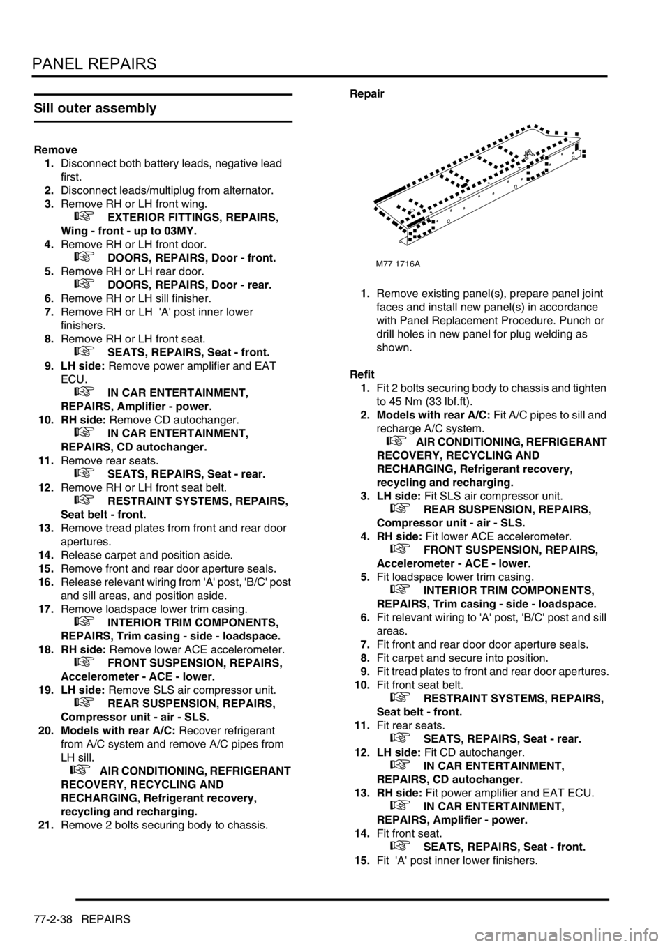
1.Remove existing panel(s), prepare panel joint
faces and install new panel(s) in accordance
with Panel Replacement Procedure. Punch or
drill holes in new panel for plug welding as
shown.
Refit
1.Fit 2 bolts securing body to chassis and tighten
to 45 Nm (33 lbf.ft).
2. Models with rear A/C: Fit A/C pipes to sill and
recharge A/C system.
+ AIR CONDITIONING, REFRIGERANT
RECOVERY, RECYCLING AND
RECHARGING, Refrigerant recovery,
recycling and recharging.
3. LH side: Fit SLS air compressor unit.
+ REAR SUSPENSION, REPAIRS,
Compressor unit - air - SLS.
4. RH side: Fit lower ACE accelerometer.
+ FRONT SUSPENSION, REPAIRS,
Accelerometer - ACE - lower.
5.Fit loadspace lower trim casing.
+ INTERIOR TRIM COMPONENTS,
REPAIRS, Trim casing - side - loadspace.
6.Fit relevant wiring to 'A' post, 'B/C' post and sill
areas.
7.Fit front and rear door door aperture seals.
8.Fit carpet and secure into position.
9.Fit tread plates to front and rear door apertures.
10.Fit front seat belt.
+ RESTRAINT SYSTEMS, REPAIRS,
Seat belt - front.
11.Fit rear seats.
+ SEATS, REPAIRS, Seat - rear.
12. LH side: Fit CD autochanger.
+ IN CAR ENTERTAINMENT,
REPAIRS, CD autochanger.
13. RH side: Fit power amplifier and EAT ECU.
+ IN CAR ENTERTAINMENT,
REPAIRS, Amplifier - power.
14.Fit front seat.
+ SEATS, REPAIRS, Seat - front.
15.Fit 'A' post inner lower finishers.
M77 1716A
Page 1107 of 1529

PANEL REPAIRS
77-2-40 REPAIRS
'B/C' post assembly
Remove
1.Disconnect both battery leads, negative lead
first.
2.Disconnect leads/multiplug from alternator.
3.Remove RH or LH rear door.
+ DOORS, REPAIRS, Door - rear.
4.Remove front door striker from 'B/C' post.
5.Remove RH or LH sill finisher.
6.Remove RH or LH front seat.
+ SEATS, REPAIRS, Seat - front.
7. RH side: Remove power amplifier.
+ IN CAR ENTERTAINMENT,
REPAIRS, Amplifier - power.
8. LH side: Remove CD autochanger.
+ IN CAR ENTERTAINMENT,
REPAIRS, CD autochanger.
9.Remove RH or LH front seat belt.
+ RESTRAINT SYSTEMS, REPAIRS,
Seat belt - front.
10.Remove RH or LH rear seat.
+ SEATS, REPAIRS, Seat - rear.
11.Remove head lining.
+ INTERIOR TRIM COMPONENTS,
REPAIRS, Headlining.
12.Remove tread plate from front and rear door
apertures.
13.Release carpet from fixings and position aside.
14.Remove front and rear door door aperture
seals.
15.Release relevant wiring from 'B/C' post and sill
areas and position aside.
16.Remove side drip rail finisher.Repair
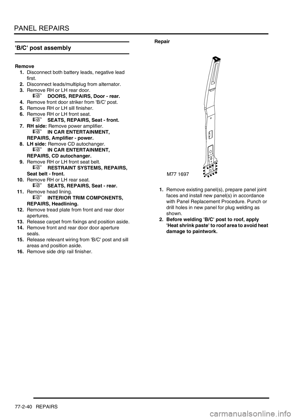
1.Remove existing panel(s), prepare panel joint
faces and install new panel(s) in accordance
with Panel Replacement Procedure. Punch or
drill holes in new panel for plug welding as
shown.
2. Before welding 'B/C' post to roof, apply
'Heat shrink paste' to roof area to avoid heat
damage to paintwork.