Page 573 of 2189

Slave Gylinder
Removal/lnstallation
CAUTION:
. Do not spill brake tluid on the vehicle; it may damage
the paint; if brake fluid does contact th€ paint, wash
it off immodiatoly with water,
. Plug the end ot the clutch line with a shop towel to
prevsnt brake fluid from coming oul.
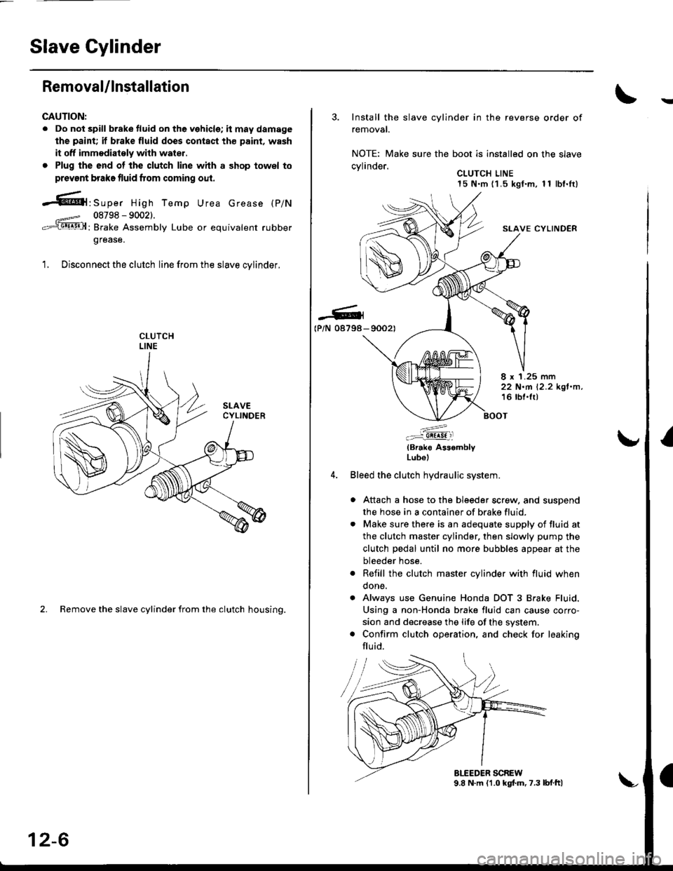
-61'srp", High Temp Urea crease (p/N
08798 - 90021.
: Brake Assembly Lube or equivalent rubber
grease.
1. Disconnect the clutch line from the slave cvlinder.
2. Remove the slave cylinder from the clutch housing.
12-6
3. Install the slave cylinder in the reverse order of
removal.
NOTE: Make sure the boot is installed on the slave
cvlinder.. CLUTCH LINE15 N.m (1 .5 kgf.m, 1 1 lbf.It)
SLAVE CYLINDER
-G4(P/N 08798- 90021
8 x 1.25 mm22 N.m 12.2 kgl.n,16 lbl.lt)
:^..:i!!!!! :l
(Brak€ AssemblyLubol
Bleed the clutch hydraulic system.
a Attach a hose to the bleeder screw, and suspend
the hose in a container of brake fluid.
. Make sure there is an adequate supply of fluid at
the clutch master cylinder, then slowly pump the
clutch pedal until no more bubbles appear at the
bleeder hose.
. Refill the clutch master cylinder with fluid when
done.
. Always use Genuine Honda DOT 3 Brake Fluid.
Using a non-Honda brake fluid can cause corro-
sion and decrease the life of the system.
. Confirm clutch operation, and check for leaking
flu id.
Page 624 of 2189
Gearshift Mechanism
Overhaul
NOTE:
.Inspectrubberpartsforwearanddamagewhendisassembling;replaceanywornordamagedparts.
. Install the clip as shown.
. Turn the boot so the hole is facing down as shown.. Make sure the boot is installed on the shift rod.
SHIFT LEVER KNOE7.8 N.m {0.8 kgf.m,5.8 lbt.tt)
EXTENSIONBOLT
)
searr'p)) p f*** \-ii,,l?'"
SHIFT -Vvvvvvvvvvvvvvvv�l tlourur Replace. | 1 22 N'm 12.2 ksf'm, 16 lbt.ftl
ii,".i'----....-.9 / g-ia',rf,',,"' sELF-LocKrNG Nur
sEAr '6 .rrr*(,o"" o-","o, ;":'i:;u --
CLIP
dul/
/,1: MOUNT
l': I cusHroN ,€\/\/-sSHIFT l / /-LEVER \, et- ffi
PY:,'\1^l lW -"or.o*Dusr .- \5".o.o)@1 -o-E "ot'o'
sHlFr \:/ Q,gD 22 N.m
IiUei__-.....p anecxer ,-/n I I I
?!il, e* ^.-.-n{wl\^fr J"r^r"
7****r
""'%ilf
t@
t1
t\sHrFT LEVER IBALL HOLDER
\
REAR JorN*lr,""17E@
_6,
L\
EXTENSION
SELF-LOCKING NUTReplace.6 x '1.0 mm9.8 N.m {1.0 kgf.m, 7.2 lbf.lr}
tJSPRING PINReplace.
-6r
16 tbf.trl
13-44
Page 677 of 2189
Gearshift Mechanism
Overhaul
NOTE:
. Inspect rubber parts for wear and damage when disassembling;
. Install the spring pin and the clip on the change joint as shown'
. Turn the shift rod boot so the hole is facing down as shown'
. Make sure the shift rod boot is installed on the shift rod'
reDlace any worn or damaged Parts.
I x 1.25 mm22 N.m 12.2 kgf.m, 16 lbf.ft)
ffi-:t't:il1ii51i?"'*,
TU
/g3i'51!Exii
V ExrENsroN
EXTENSfON ilr'eol.T
EXTENSION ENDBUSHING
hV\
EXTENSIONWASI{ER B
MOUNT -_.--_-_---
@2'
--1'>=2 -:liT.i'ff"
.o,-.o*&--ffi{---*,
v/,,/ BALL SEAT
8 x 1.25 mm22 N.m 12.2 kgf'm, 16lblftl
,@
EXTENSION ROD
SHIFT ROD
SPRING
END
BOOT
N: g sHrFr LEvER
.*rr"r,o"-tf V-oiliiSi[a
MOUNTING I --::=t SHIFT I"EVERBRAcxEr / €9-l--enr xoloen
8 x 1.2s mm :-,rro""a,ii-ri- ri.z rsr.-, -.Q u
16 tbf.ft) ,,,.
,rar-aoa*,"o "u, / E ,",t.ruaa
Replace.6x1.0mm9.8 N.m ('1.0 kgt'm,7 tbr.ftt
8x22mmSPRING PINReplace.
IIt
@CLIP
9.a-"t't
PIN SHIFT ROD/
ZW
€lt#-,\
HOLE
13-97
Page 1041 of 2189
Driveshafts
Reassembly
U.S. and Canada-Producad Driv€shafts
Note these items during reassembly'
. Clean the disassembled parts with solvent, and dry them thoroughly with compressed air, Do not wash the rubberpans with solvent.
o ;..jl@l : Thoroughly pack the inboard joint and both joint boots with the joint grease included in the new driveshaft
ser,
Grease quantity:
lnboard Joint115 - 135 g (4.0 - 4.8 oz)
Outboard Joint115 - 135 g (4.0 - 4.8 oz)
. The'98 Canada model and all '99 - 00 models uses a TPE (Thermoplastic Polyester Elastomerl outboard joint boot. Use
the ear clamp type boot band in the outboard joint boot set.
STOP RING('96 - 98 models)
-6rPack cavity with grease.
DYNAMIC DAMPER
OOUBI.S LOOP BANDReplace.
INBOARD BOOT
-6lPack cavity with grease.
EAB CLAMP BANDReplace.
STOP RINGReplace.
EAR CLAMP BANDReplace.
DRIVESHAFT
OUTBOARDBOOT ITPE)
-6ll
, Pack cavity with grease.
EAR CLAMP BANDReplace.
-G.1
CIRCLIP
16-8
OUTBOARD JOINT
Page 1042 of 2189
l/
tt
Brazil-Produced Driveshafts
Note these items during reassembly
. clean the disassembled parts with solvent, and dry them thoroughly with compressed ajr. Do not wash the rubber
parts with solvent.
. .fut :Thoroughly pack the inboard joint and both joint boots with the joint grease included in the new driveshaft
ser.
Greas€ quantity:
lnboard Joint115 - 135 g (4.0 - 4.8 ozl
Outboard Joint115 - 135 g {4.0 - 4.8 oz)
INSOARD JOINT
DRIVESHAFT
BOOT BANDSReplace.
-6.lPack cavity
(cont'd)
16-9
l,z
wrth grease,
Page 1043 of 2189

Driveshafts
Reassembly (cont'dl
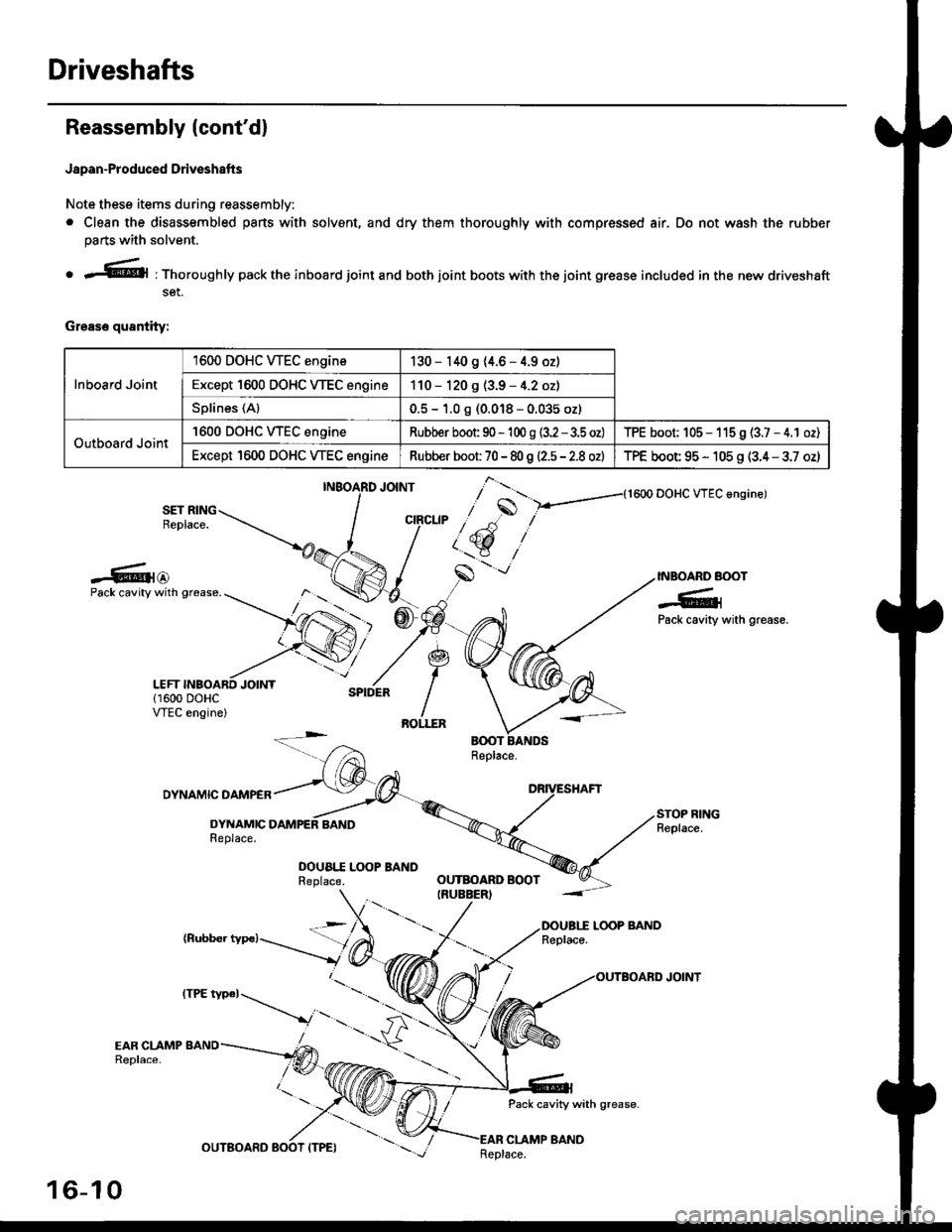
Japan-Produced Driveshafts
Note these items during reassembly.
. Clean the disassembled pans with solvent, and dry them thoroughly with compressed air. Do not wash the rubber
parts with solvent.
o r@l : Thoroughly pack the inboard joint and both joint boots with the joint grease included in the new driveshaft
set.
Grease quantity:
Inboard Joint
1600 DOHC WEC engine130 - 140 9 (4.6 - 4.9 oz)
Except 1600 DOHC VTEC engine110 - 120 g (3.9 - 4.2 oz)
Splines (Al0.5 - 1.0 g (0.018 - 0.035 oz)
Outboard Joint
'1600 DOHC WEC engineRubber boot 90 - 'l 00 g (3.2 - 3.5 oz)TPE boot; 105 - 115 9 (3.7 - 4.1 oz)
Except 1600 DOHC VTEC engineRubber boot 70 - 80 g |'2.5 - 2.8 ozlTPE boot 95 - 105 g (3.4 - 3.7 oz)
{1600 DOHC VTEC angine)
SET RINGReplace.
-6{@INBOARD BOOT
-6;Pack cavity with grease.
Pack cavity with grease.
DYNAMIC DAMPER
DYNAMICReplace.
DOUA|.I Lq)P BANDReplace.
(Rubber typc)LOOP BANDReplace.
Pack cavity with grease-
CLAMP BAND
],*"u, ,"^S
/ t'.t$ ,''
,/s
-'-
OUTBOARD BOOTIRUEBER)
16-10
tttt t*' -----_.r...-
._
Replace.
Page 1047 of 2189
Driveshafts
17.
Reassembly (cont'dl
Unwind the boot band tool, and cut off the excess 5- 10 mm (0.2 - 0.4 in) from the clip.
5-10mm10.2 - 0.a inl
Secure the end of the boot band by tapping it downwith a hammer,
19. Installthe new set ring,
18.
Note these items after reassembly:. Make sure the band and clip does notanything and the band does not move.a Remove any grease remaining on thesurfaces.
interfere with
su rrou nding
16-14
Outboard Joint Sid.:
1. Wrap the splines with vinyl tape to prevent damageto the boot.
TPE tvDe:-. OUTBOARO BOOT ITPE)
BOOT BANDReplac€,
Rubber typ.:
Install the boot band and outboard boot, thenremove the vinyl tape. Take care not to damage theboot,
Install the stop ring into the driv€shaft groove.
DRIVESHAFT
>VINYL TAPE
VINYL TAPE
Page 1049 of 2189
Driveshafts
Reassembly lcont'd)
Installthe outboard boot and the boot bands.. lf the boot is the rubber type. go to step 13.. lf the boot is the TPE type, go to step 9.
Fit the boot ends onto the driveshaft and outboard
ioint.
10, Set the ear clamp band by threading the tab into theholes of the band.
EAR CLAMP BANDReolace.
8.
16-16
11. Close the ear portion of the band with a commer-cially available boot band Dincerc.
BOOT BAND PINCERSKENT-MOORE J,35910or eouivalent
Chsck the clearanca between the closed ear oonionof the band. lf the clesrance is not within the stan-
dard, close the ear portion of ths band further.
6.0 mm (0.24 in) MAX
3.0 mm 10.t2 inl MAX
EAR FOFNON