1999 HONDA CIVIC spindle
[x] Cancel search: spindlePage 1036 of 2189
Driveshafts
Inspection
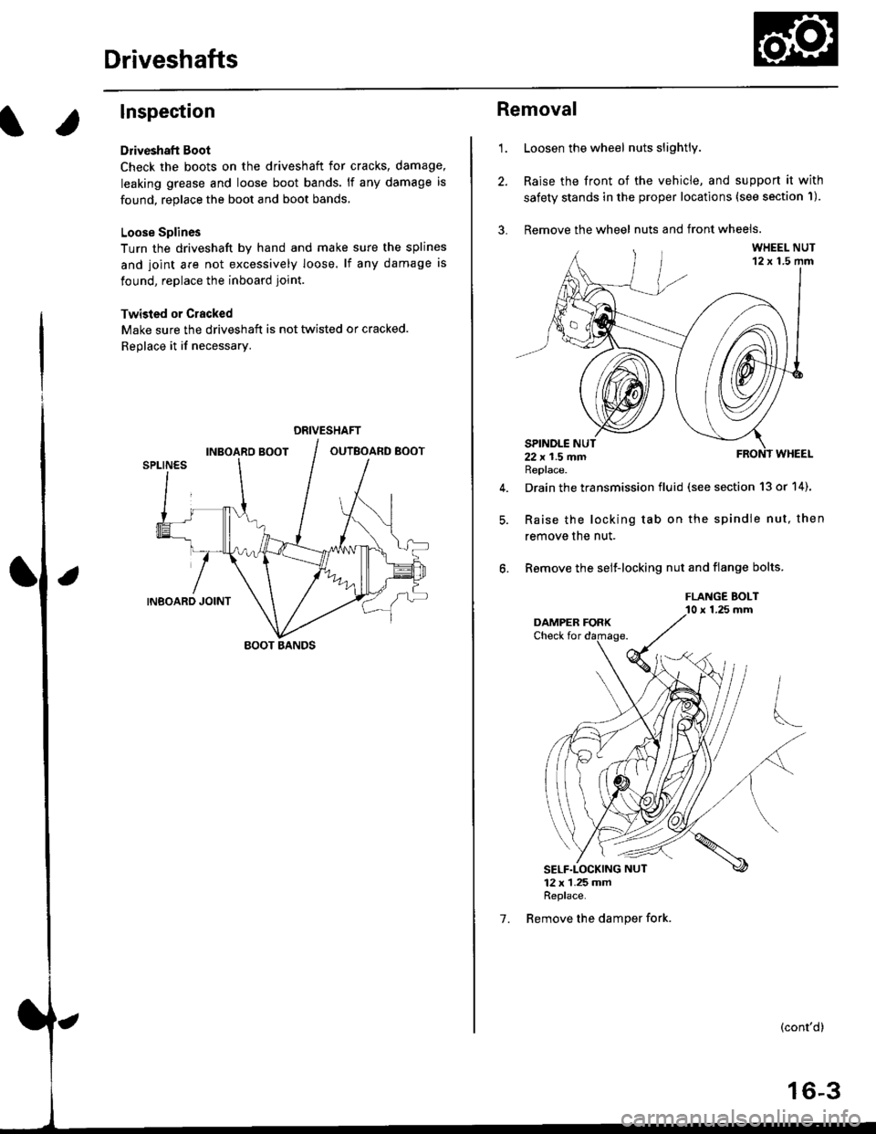
Driveshaft Boot
Check the boots on the driveshaft for cracks, damage,
leaking grease and loose boot bands. lf any damage is
found, replace the boot and boot bands,
Loose Splines
Turn the driveshaft by hand and make sure the splines
and joint are not excessively loose. lf any damage is
found, replace the inboard joint.
Twisied or Cracked
Make sure the driveshaft is not twisted or cracked.
Reolace it if necessarv.
DRIVESHAFT
BOOT BANDS
1.
Removal
Loosen the wheel nuts slightly.
Raise the front of the vehicle, and support it with
safety stands in the proper locations (see section 'l).
Remove the wheel nuts and front wheels.
Drain the transmission fluid (see section 13 or 14).
Raise the locking tab on the spindle nut, then
remove the nut.
Remove the selJ-locking nut and flange bolts.
FLANGE BOLT10 x 1.25 mm
(cont'd)
16-3
1.
Page 1052 of 2189
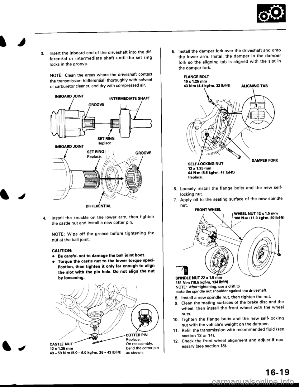
3. lnsert the inboard end of the driveshaft into the dif-
terential or intermediate shaft until the set ring
locks in the groove
NOTE: Clean the areas where the driveshaft contact
the transmission (differential) thoroughly with solvent
or carburetor cleaner, and dry with compressed air'
INBOARD JOINT
INBOARD JOINTReplace.
GROOVE
an
DIFFERENTIAL
lnstall the knuckie on the lower arm. then trghten
the castle nut and install a new cotter pin
NOTE: wipe off the grease before tightening the
nut at the ball ioint.
CAUTION:
. Be careful not to damago the ball ioint boot'
. Torque the castle nut to the lower torque sp€ci-
fication, thsn tighten it only far enough to align
the slot with th€ pin hol6. Do not align the nut
by loosening.
CASTLE NUT12 x 1 .25 mm
COTTER PINReplace.On reassemblY,bend the cotter pinJi$ - 59 N.m 15.0 - 6.0 kgl m,35 - 43 lbf ftl
16-19
5. lnstall the damper tork over the driveshaft and onto
the lower arm. Install the damper in the damper
fork so the aligning tab is aligned with the slot in
the damPer fork.
FLANGE BOLTl0 r 1.25 mmrit N.m t4.a kgf.m, 32 lbf.ft) AIIGN|NG TAB
1.
SELF-LOGKING NUT12 x 1.25 mm6,1N.m 16.5 kgi.m, a7 lbfftl
Replace.
Loosely install the flange bolts and the new self-
locking nut.
Apply oil to the seating surface of the new spindle
nut.
181 N m 118.5 kgt'm, 13il lbt'ftl
NOTE: Aftortightening, use a drift to
stake the spindle nut shoulder against the drivoshaft'
8. Install a new spindle nut, then tighten the nut'
9. Clean the mating surfaces ot the brake disc and the
wheel. then install the front wheel with the wheel
nuts.
10. Tighten the flange bolts and the new self-locking
nut with the vehicle's weight on the damper.
11. Refill the transmission with recommended fluid (see
section 13 or 14).'t2. Check the front wheel alignment and adjust if nec-
essary (see section 18),
FRONT WHEEL
SPINDLE NUT 22 x 1.5 mm
WHEEL NUT 12 x 1.5 mm108 N.m (11.0 kgl'm, g) lbl ftl
Page 1134 of 2189
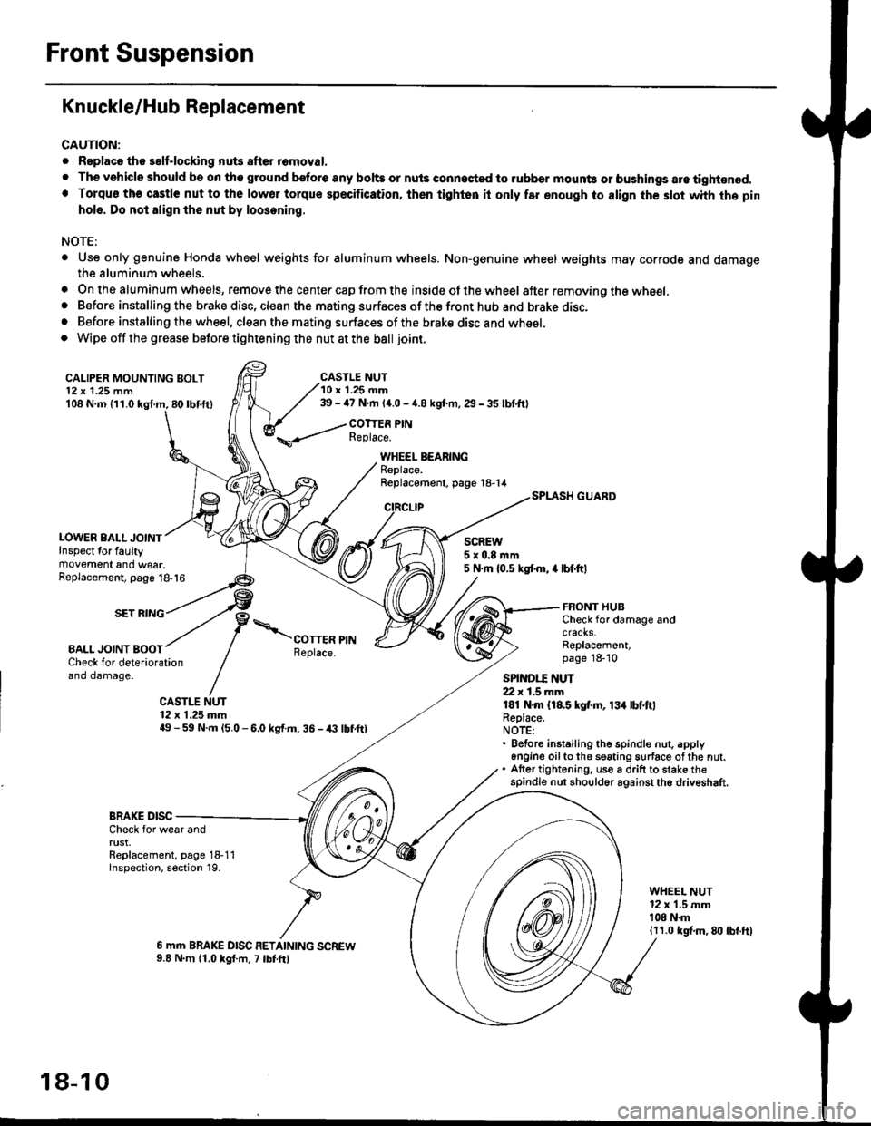
Front Suspension
Knuckle/Hub Replacement
CAUTION:
. Replaco tho salf-locking nuts after romoval.
. The vehiclo should be on tho ground bsfore any bohs or nuls connected to rubber mounb or bushings are tightened.. Torqu€ th€ castle nut to the lowor torque specification, ihen tighton it only far enough to align th€ slot whh the pin
hole. Do not align the nut by loosening.
NOTE:
. Use only genuine Honda wheel weights for aluminum wheels. Non-genuine wheel weights may corrode and damagethe aluminum wheels.
. On the aluminum wheels, remove the center cap from the inside of the wheel after removing the wheel,. Before installing the brake disc, clean the mating surfaces of the front hub and brake disc,. Before installing the wheel, clean the mating surfaces of the brake disc and wheel.o Wipe off the grease before tightening the nut at the ball joint.
CALIPER MOUNTING BOLT12 x 1.25 mm108 N.m {11.0 kgl.m, 80lbf.ft)
LOWER BALL JOINTInspect for faultymovement and wear.
CASTLE NUT10 r 1.25 mm39 - ia7 N.m (4.0 - 4.8 kgf.m, 29 - 35 lbf,ftl
COTTER PINReplace.
WHEEL BEARINGReplace.Replacement, page 18-14
CIRCLIP
SCREW5x0.8mm5 N.m {0.5 ksl.m, 4 lbf.ftlReplacement, page 18-16
SET RING
BALL JOINT BOOT
FRONT HUBCheck for damage andcracks.Replacement,page 18-10Check for deteriorationand damage.
CASTLE NUT12 x 1.25 mm49 - 59 N.m l5.O - 6.0 kg{.m. 36 - /(} lbf,ftl
SPINDI.T ]{UT22 r 1.5 mmlEl N.m {18.5 kgf.rn, 13{ lbl.ttlReplace.NOTE:. Before instelling the spindle nut. apply6n9ine oilto th6 seating surface ofthe nut.. Atter tightening, uso a drift to stake thespindle nut should6r against the driveshaft.
BRAKE DISCCheck for wear andrust.Replacement, page 18-11lnspection, section 19.
WHEEL NUT12 x 1.5 mm'108 N.m1r1.0 kgf.m, 8lt lbf.ft)
6 mm BRAKE DISC RETAINING SCREW9.8 N.m 11.0 kgf.m, 7 lbtft)
18-10
Page 1135 of 2189
)
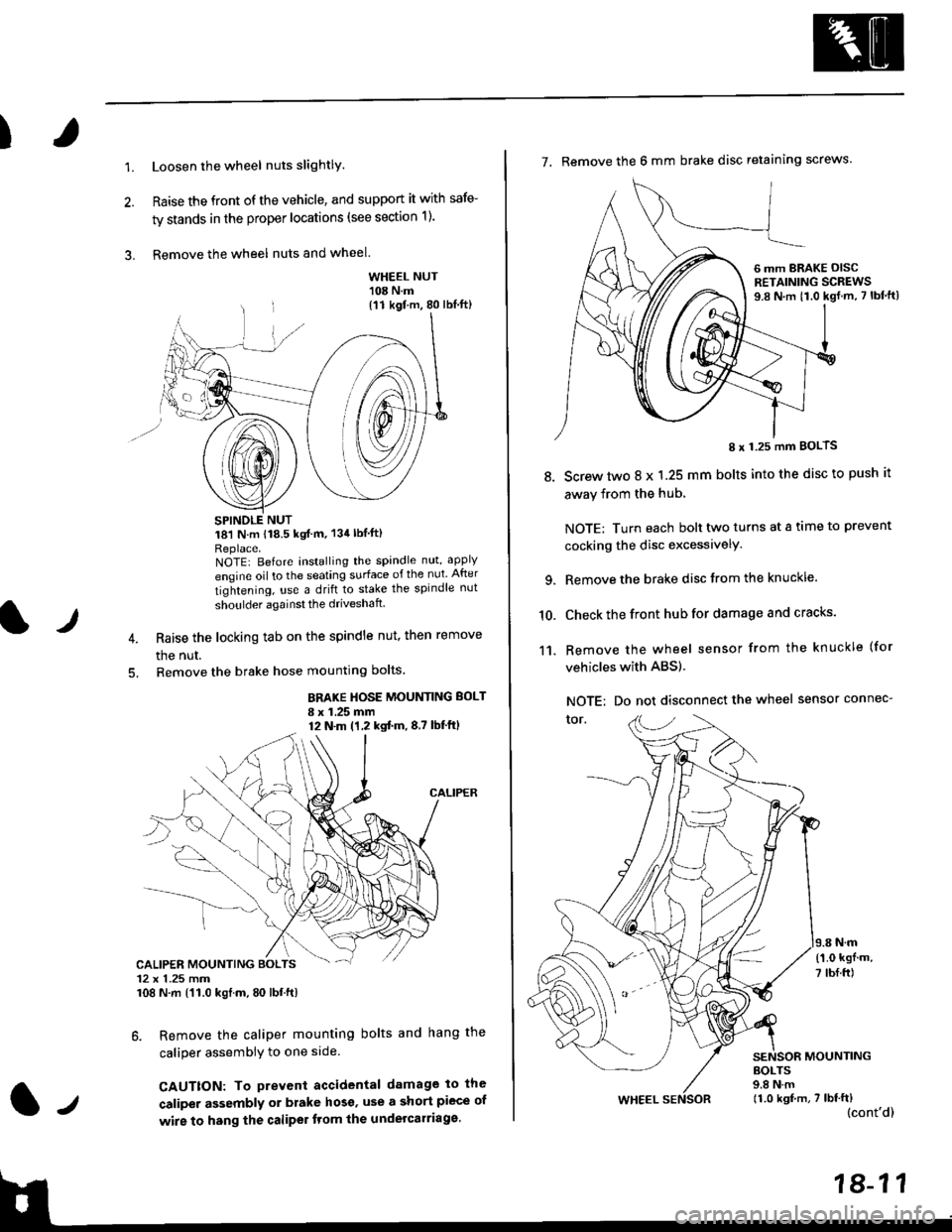
1.Loosen the wheel nuts slightlY.
Raise the front of the vehicle, and support it with safe-
ty stands in the proper locations (see section 1).
Remove the wheel nuts and wheel.3.
l)
WHEEL NUT'108 N.m
18'l N.m 118.5 kgf m, 134lblfti
Replace.NOTEI Before installing the spandle nut, apply
engine oil to the seating surface of the nut After
tightening, use a drift to stake the spindle nut
shoulder againsl the driveshaft
Raise the locking tab on the spindle nut, then remove
the nut.
Remove the brake hose mounting bolts.
BRAKE HOSE MOUNTING BOLT
I x 1.25 mm12 N.m (1,2 kgtm,8,7 lbf'ftl
6. Remove the caliper mounting bolts and hang the
caliper assembiy to one side
CAUTTON: To prevent accidental damage to the
caliper assembly or brake hoso' use a short piece of
wire to hang the caliPer tlom lhe undelcarriage.
{11 kgf m, 80 lbl.ft)
CALIPER MOUNTING BOLTS12 x 1.25 mm108 N.m {'11.0 kgtm, 80 lbt.ft)
7. Remove the 6 mm brake disc retaining screws.
8.
I x 1.25 mm BOLTS
Screw two 8 x 1.25 mm bolts into the disc to push it
away from the hub,
NOTE: Turn each bolt two turns at a tame to prevent
cocking the disc excessivelY.
Remove the brake disc from the knuckle.
Check the front hub for damage and cracks.
Remove the wheel sensor from the knuckle (for
vehicles with ABS).
NOTE: Do not disconnect the wheel sensor connec-
tor.
N.m
6 mm BRAKE OISCRETAINING SCREWS9.8 N.m t1.0 kgf.m, 7 lbf'ft)
{'1.0 kgf m,
7 tbf.ft)
10.
11.
MOUNTING
WHEEL
BOLTS9.8 N.m11.0 kgf,m, 7 lbf'ft)(cont'd)
Page 1147 of 2189
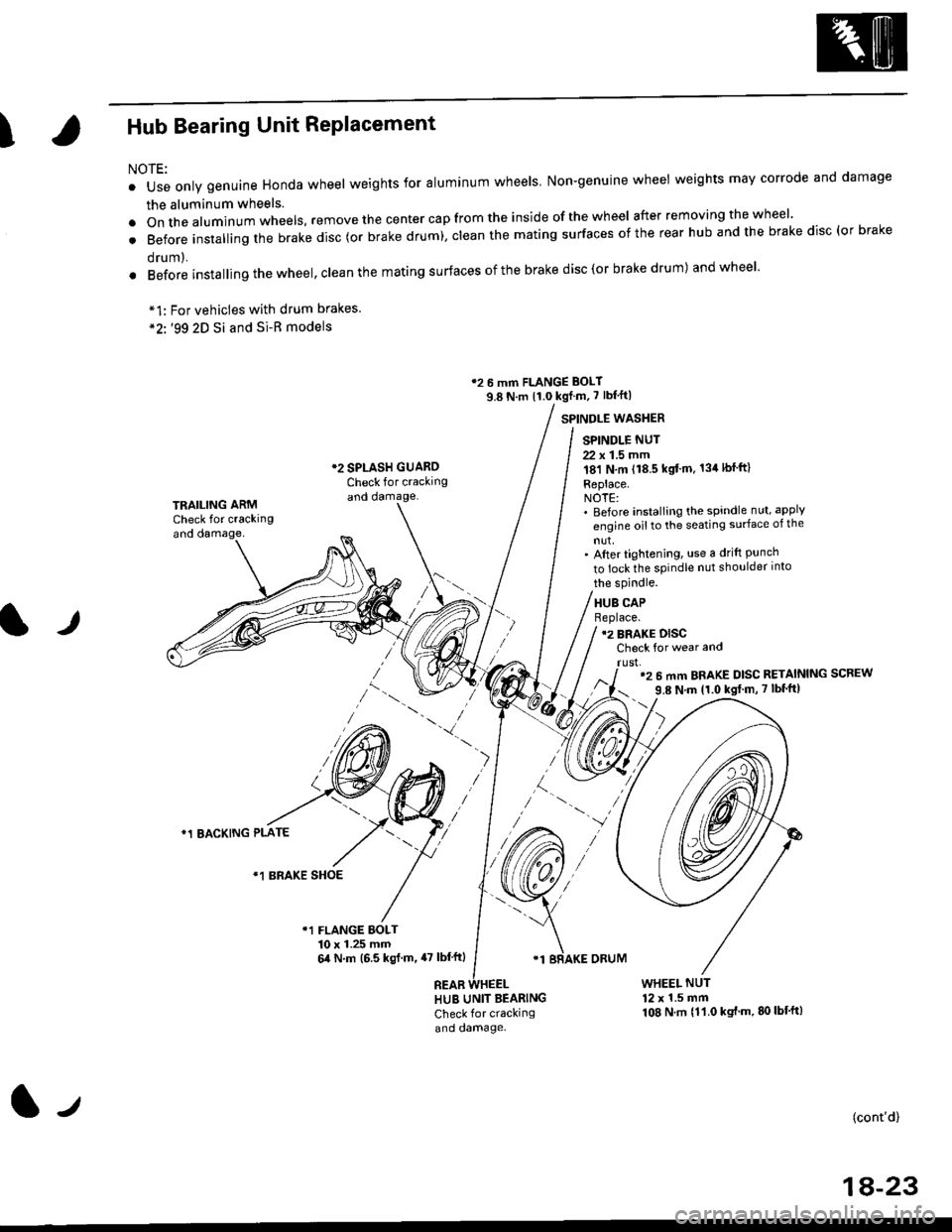
IHub Bearing Unit RePlacement
For vehicles with drum brakes.'99 2D Si and Si-B models
NOTE:
o Use only genuine Honda wheel weights for aluminum wheels Non-genuine wheel weights may corrode and damage
the aluminum wheels.
.onthea|uminumwhee|s,removethecentercapfromtheinsideoftheWhee|afterremovingthewhee|'
. Before insta||ing the brake disc (or brake drum), c|ean the mating surfaces of the rear hub and the brake disc (or brake
orum,.
. Before installing the wheel, clean the mating surfaces ofthe brake disc(or brake drum) andwheel'
*1:
*2'.
12 6 mm FLANGE BOLT
9.8 N.m {1.0 kgf m, 7 lbf'ft|
*2 SPLASH GUAROCheck for crackingand damage.
SPINDLE WASTIER
SPINDLE NUT
22 x 1.5 mm181 N,m (18.5 kgt'm. 134lbfft)
Replace.NOTE:' Before installing the spindle nut, apply
engine oil to the seating surface of the
nut,' After tightening, use a drift Punchto lock the spindle nut shoulder into
TRAILING ARMCheck for crackingand oamage,
lr
the spindle.
HUB CAPBeplace.12 BRAKE DISCCheck for wear and
rust,'2 6 mm BRAKE DISC RETAINING SCREW
9.8 N'm 11.0 kgt m, 7 lbf'ft|
)
*1 BACKING PLATE
/\*1 BRAKE SHOE
r1 FLANGE BOLT10 x 1.25 mm6,0 N.m (6.5 ksl.m,47 lbl'ftl
REAB
'1 BRAKE ORUM
HUB UNIT BEARING
Check for crackingand damage.
WHEEL NUT12 x 1.5 mm108 N.m {11.0 kgt'm.80lbt'ft)
(cont'd)
1A-23
l-t
Page 1148 of 2189
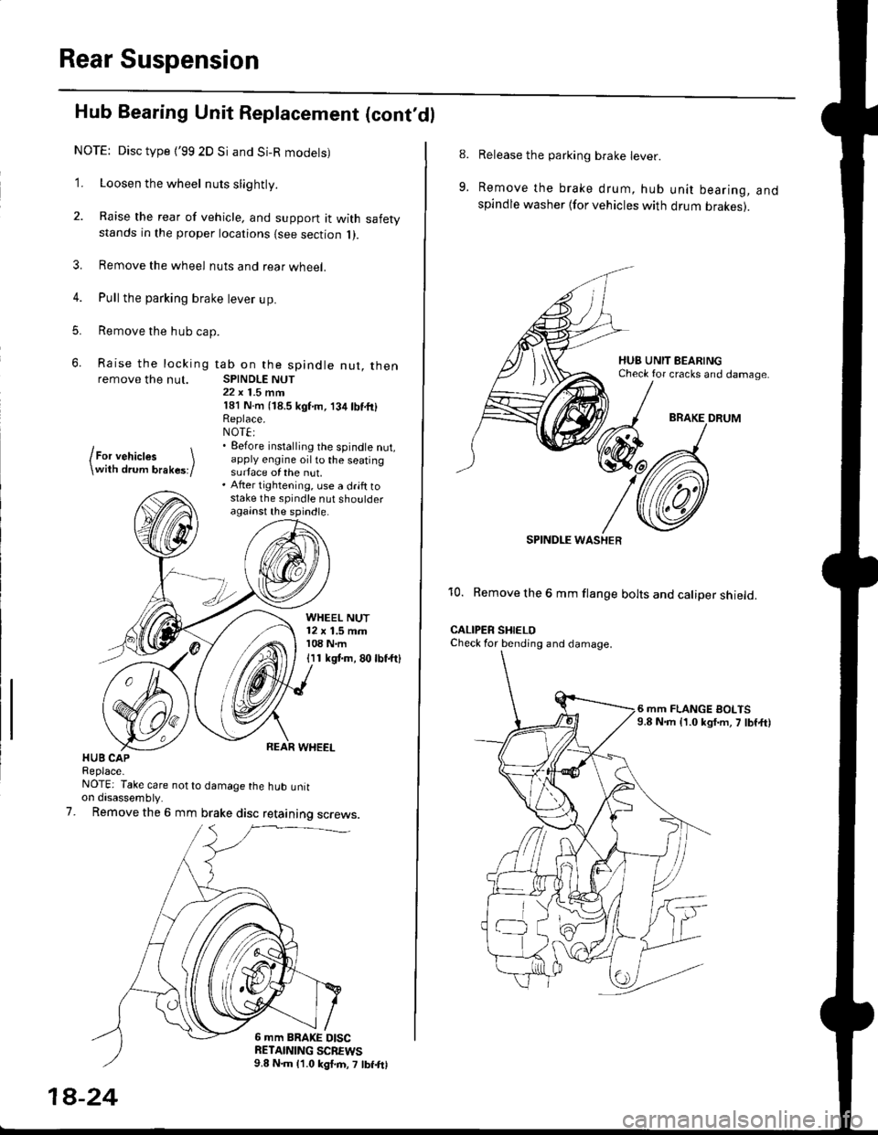
Rear Suspension
Hub Bearing Unit Replacement (cont'dl
NOTE: Disc type {'99 2D Si and Si-R modets)
1. Loosen the wheel nuts slightly.
2. Raise the rear of vehicle, and support it with safetystands in the proper locations {see section 1).
3. Remove the wheel nuts and rear wheel.
4. Pull the parking brake lever up.
5. Remove the hub cap.
6. Raise the locking tab on the spindle nut, thenremove the nut. SPINDLE NUT22 x 1.5 mrn181 N.m (18.5 kgf'm, 134lbf.fi)Replace.NOT€:. Eefore installing the spindle nut,apply engine oil to the seatingsurface of the nut.. After tightening, use a drift tostake the spindle nut shoulderagainst the spindle.
lFor vehictes \\with drum brakes;/
WHEEL NUT12 x 1.5 mm108 N.m
I I 1 kgt m, 80 lbf.ftl
HUB CAPReplace-NOTE: Take care not to damage the hub untton disassembly.
Remove the 6 mm brake disc retaining screws.7.
6 mm BRAKE DISCRETAINING SCBEWS9.8 N.m 11.0 kgl.m, 7 lbf.frl
1A-24
8.
9.
Release the parking brake lever.
Remove the brake drum, hub unit bearing, andspindle washer lfor vehicles with drum brakes).
BRAKE DRUM
SPINDI-E WASHER
10. Remove the 6 mm flange bolts and caliper shield.
CALIPER SHIELOCheck for bending and damage.
6 mm FLANGE BOLTS9.8 N.m {1.0 kgf.m, 7 lbf,ft)
Page 1149 of 2189
T
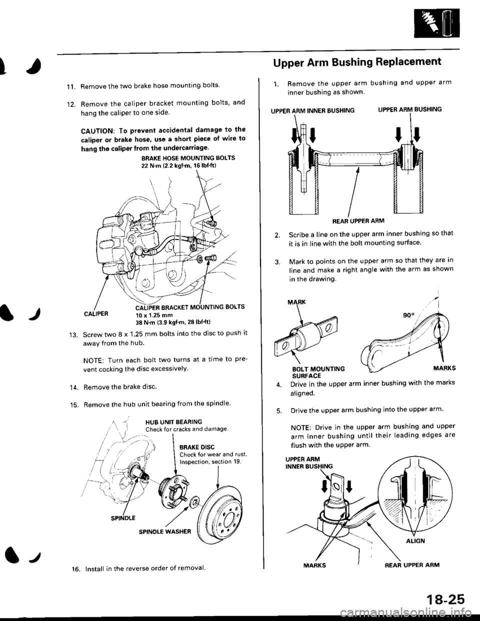
11.
1)
Remove the two brake hose mounting bolts
Remove the caliper b.acket mounting bolts, and
hang the caliPer to one side
CAUTION: To prevent accidental damage to the
caliper or brake hose, use a short piece of wile to
hang the caliper from the undercarriage.
BRAKE HOSE MOUNTING BOLTS
22 N'm {2.2 kgf'm, 16lbt"ft}
CALIPER 10 x 1.25 mm38 N'm (3.9 kgf'm, 28 lbf'ftl
Screw two 8 x 1.25 mm bolts into the disc to push it
away from the hub.
NOTE: Turn each bolt two turns at a time to pre-
vent cocking the disc excessively.
Remove the brake disc.
Remove the hub unit bearing from the spindle
SPINOLE WAS}IER
lr
14.
15.
lt
16. lnstall in the reverse order of removal.
1A-25
Upper Arm Bushing RePlacement
1. Remove the upper arm bushing and upper arm
jnner bushing as shown
UPPER ARM INNER BUSHING UPPER ARM BUSHING
REAR UPPER ARM
Scribe a line on the upper arm inner bushing so that
it is in line with the bolt mounting surface
Mark to points on the upper arm so that they are In
line and make a right angle with the arm as shown
in the drawing.
BOLT MOUNTINGSURFACE
Drive in the upper arm inner bushing with the marks
aligned.
Drive the upper arm bushing into the upper arm
NOTE: Drive in the upper arm bushing and upper
arm inner bushing until their leading edges are
flush with the uPPer arm
ttI
5.
UPPER ARM