Page 72 of 2189

ILubrication Points
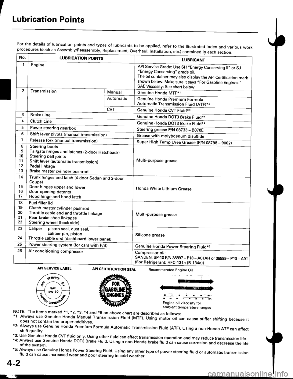
For the details of lubrication points and types of lubricants to be applied, refer to the lllustrated Index and various workprocedures (such as Assembly/Reassembly, Replacement, Overhaul. Installation, etc.) contained in each section.
No.LUBRICATION POINTS
Engine
LUBRICANT
"Energy Conserving" grade oil,The oil container may also display the Apl Certification markshown below. Make sure it says ,,For Gasoline Engines.,,SAE Viscosity: See chart below,
I
TransmissionManualGenuine Honda MTF*1
Genuine Honda Premium FormulaAutomatic Transmission Fluid (ATF)*,
Genuine Honda CVT Fluid*3
Genuine Honda DOT3 Brake Fluid*a
Automatic
CVT
3Brake Line
ClL,tci t""e4
I
Genuine Honda DOT3 Brake Fluid*aPower steering gearboxSteering grease P/N 08733 - BO70EShift lever pivots (manual transmission)Grease with molybdenum disulfide7-:ti
9
10'l'l
l3
14
't7
18
19
20
2122
Release fork (manual trancmi
Steering bootsTailgate hinges and latches (2-door HatchbacklSteering ball joints
Shift lever (automatic transmission)Pedal linkageBrake master cylinder pushrod
Super High Temp Urea crease (p/N 08798 - 9OO2)
i Multi-purpose grease
I
I
Honda White Lithium Grease
Multi-purpose grease
Silicone grease
@
Trunk hinges and latch (4-door Sedan and 2-doorCoupe)Door hinges upper and lowerDoor opening detentsHood hinge and hood latch-FUet T ter ttd
Clutch master cylinder pushrodThrottle cable end and throttle linkageRear brake shoe linkagesSteering wheel (back side)
23
E-
Caliper piston seal, dust seal,caliper pin. pistonThrottle cable end (dashboard lower panel)
Power steering system (for cars with p/S)
Air conditioning compressorComDressor oil:SANDEN: SPlo P/N 38897 - p13 -A01AH or 38899 - p13_ A01{For Refrigerant: HFC-134a (R-134a))
CERTIFICATION SEAL
ffi
NorE: The items m arked * 1, *2, +3, *4 and +5 on above chan are described as folows:*1: Always use Genuine Honda Manual Transmission Fluid (MTF). Using motor oil can cause stiffer shifting because itdoes not contain the proper additives.*2: Always use Genuine Honda premium Formula Automatic Transmission Fluid (ATF). Using a non-Honda ATF can affectshift quality.+3: Use Genuine Honda cVTfluid only usingotherfluid can affect tra nsmission operation and may reduce transmission life.*4: Always use Genuine Honda DoT3 Brake Fluid. Using a non-Honda brake fluid can cause corrosion and dec.ease the lifeof the svstem.*5: Always use Genuine Honda Power steering Fluid. using any other type of power steering fluid or automatrc transmissionfluid can cause increased wear and poor steering in cold weather.
4-2
Recommended Engine Oil
Engine oil viscosity forambrent temperature ranges
API SERVICE LABEL
Page 573 of 2189

Slave Gylinder
Removal/lnstallation
CAUTION:
. Do not spill brake tluid on the vehicle; it may damage
the paint; if brake fluid does contact th€ paint, wash
it off immodiatoly with water,
. Plug the end ot the clutch line with a shop towel to
prevsnt brake fluid from coming oul.
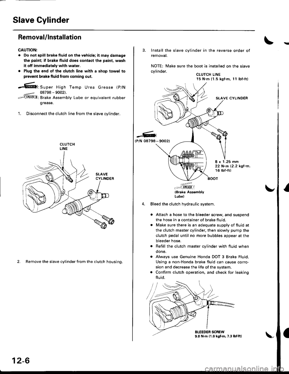
-61'srp", High Temp Urea crease (p/N
08798 - 90021.
: Brake Assembly Lube or equivalent rubber
grease.
1. Disconnect the clutch line from the slave cvlinder.
2. Remove the slave cylinder from the clutch housing.
12-6
3. Install the slave cylinder in the reverse order of
removal.
NOTE: Make sure the boot is installed on the slave
cvlinder.. CLUTCH LINE15 N.m (1 .5 kgf.m, 1 1 lbf.It)
SLAVE CYLINDER
-G4(P/N 08798- 90021
8 x 1.25 mm22 N.m 12.2 kgl.n,16 lbl.lt)
:^..:i!!!!! :l
(Brak€ AssemblyLubol
Bleed the clutch hydraulic system.
a Attach a hose to the bleeder screw, and suspend
the hose in a container of brake fluid.
. Make sure there is an adequate supply of fluid at
the clutch master cylinder, then slowly pump the
clutch pedal until no more bubbles appear at the
bleeder hose.
. Refill the clutch master cylinder with fluid when
done.
. Always use Genuine Honda DOT 3 Brake Fluid.
Using a non-Honda brake fluid can cause corro-
sion and decrease the life of the system.
. Confirm clutch operation, and check for leaking
flu id.
Page 578 of 2189
Release Bearing
)
4. Torque the mounting bolts in a crisscross pattern as
shown. Tighten them in several steps to prevent
warping the diaPhragm sPring.
19 rbf.ft)
\
RING GEAR HOLDERoTLAB-PV00100ot07924-PD20003
CLUTCH ALIGNMENT SHAFT
OTJAF_PM7O12AHANOLE07936-3710100
MOUNTING BOLTS
8 x 1.25 mm
25 N.m (2.6 kgl'm.
Removal/lnspection
1. Remove the release fork boot from the clutch hous-
Ing.
2. Remove the release fork from the clutch housing by
squeezing the release fork set spring with pliers
Remove the release bearing.
Check the release bearing for play by spinning it by
hand.
CAUTION: The releass bearing is packed with
grease. Do not wash it in solvent.
lf there is excessive play, replace the release bear-
ing with a new one.
RELEASE FORK
12-11
Page 579 of 2189
Release Bearing
Installation
NOTE: Use only Super High Temp Urea Grease(P/N 08798 - 9002).
1. With the release fork slid between the release bear-
ing pawls, install the release bearing on the main-
shaft while inserting the release fork through the
hole in the clutch housing.
RELEASE FORK BOLT12 x 'l .25 mm
tP/N 0a79a-90021O.3-0.9 s 10.01 -O.03 ozl
Align the detent of the release fork with the release
fork bolt, then press the release fork over the
release fork bolt sequarely.
-Gr08798-9002)
2.
12-12
IJ
3. Move the release fork right and left to make surethat it fits properly against the release bearing, and
that the release bearing slides smoothly.
4. Install the release fork boot; make sure the bootseals around the release fork and clutch housino.
Page 589 of 2189

. Torque the mounting bolt and nuts in the sequence
shown.
O 12 x 1.25 mm64 N.m {6.5 kgt.m,47 lbf.fr)
@ 12 x 1.25 mm74 N.m (7.5 kgl'm,54 tbt.fr)
Check that the bushings are not twisted or offset.
Install the clip as shown.
SHIFT ROD
Turn the boot so the hole is facing down.
Make sure the boot is installed on the shift rod.
O) 12 x 'l.25 mm64 N.m 16.5 kgl.m,47 tbt.ft)
I
a
a
a
a
8 x 1.25 mmN.m t2.2 kgt.m, l6 lbl'tt)
6 x 1.0 mm9.8 N.m (1.0 kgl.m.7.2 tbf.tr)
. Apply grease to the slave cylinder push rod.
NOTE: Use only Super High Temp Urea Grease
{P/N 08798 - 9002}.
CLUTCHUNE
a
a
(P/N-6tl
08798-9002)
8 x 1.25 mm22 N.m 12.2 kgl.n.16 tbf.frl
. Turn the breather cap so that the "F" mark points at
the front of the car as shown.
Refill the transmission with the recommended oil
(see page 13-3).
Connect the positive (+) cable first, then the negative
(-) cable to the battery.
Check the clutch oDeration,
Shift the transmission and check for smooth opera-
tion.
Check the front wheel alignment (see section 18).
FRONT
13-9
Page 619 of 2189

Transmission
Reassembly
NOTE: The steel balls are all ofthe same size (5/16 in).
1. Install the magnet and reverse lock cam.
2. Set shift arm A on the clutch housing, then install
the shift rod.
3. Install the spring washer and shift arm A attaching
bolt.
Installthe steel ball, spring, and set ball spring bolt.
Install shift arm B in the interlock, then set it on the
clutch housing.
1.
Insert shift arm shaft in the clutch housing.
Install the collar, spring. and steel ball into the case.
Compress the ball and insert the shift arm shaft,
Install shift arm C in shift arm A, then insert the shift
arm shaft.
Install the reverse select retainer and reverse select
spring onto shift arm shaft.
Install the differential assembly.
5.
8.
9.
10.
A:8x1.0mm3'l N,m (3.2 kgt.m,23 lbf.ft)
6 x 1.0 mm15 N.m 11.5 kgt.m, 11 lbt'ftl
OIL SEALReplace.
SI{IFT ARM C
COLLAR
REVERSE SELECT SPRINGL. 63.4 mm 12.50 in)
REVERSE LOCK CAM
REVERSE SELECT RETAINER
sHtFT ARM ' ___\.*^
rNrERLocK p
|Jiiill---=l@
MAGNET
SET BALL SPRING BOLT22 N.m 12.2 kgl.m, 16 lbf'ftl
SPRINGL. 25.6 mm (1.O1 in)
SHIFT AFM A
CLUTCHHOUSING
SHIFT ARM SHAFT
(cont'd)
13-39
SHIFT ROD
l
BOOT
Page 624 of 2189
Gearshift Mechanism
Overhaul
NOTE:
.Inspectrubberpartsforwearanddamagewhendisassembling;replaceanywornordamagedparts.
. Install the clip as shown.
. Turn the boot so the hole is facing down as shown.. Make sure the boot is installed on the shift rod.
SHIFT LEVER KNOE7.8 N.m {0.8 kgf.m,5.8 lbt.tt)
EXTENSIONBOLT
)
searr'p)) p f*** \-ii,,l?'"
SHIFT -Vvvvvvvvvvvvvvvv�l tlourur Replace. | 1 22 N'm 12.2 ksf'm, 16 lbt.ftl
ii,".i'----....-.9 / g-ia',rf,',,"' sELF-LocKrNG Nur
sEAr '6 .rrr*(,o"" o-","o, ;":'i:;u --
CLIP
dul/
/,1: MOUNT
l': I cusHroN ,€\/\/-sSHIFT l / /-LEVER \, et- ffi
PY:,'\1^l lW -"or.o*Dusr .- \5".o.o)@1 -o-E "ot'o'
sHlFr \:/ Q,gD 22 N.m
IiUei__-.....p anecxer ,-/n I I I
?!il, e* ^.-.-n{wl\^fr J"r^r"
7****r
""'%ilf
t@
t1
t\sHrFT LEVER IBALL HOLDER
\
REAR JorN*lr,""17E@
_6,
L\
EXTENSION
SELF-LOCKING NUTReplace.6 x '1.0 mm9.8 N.m {1.0 kgf.m, 7.2 lbf.lr}
tJSPRING PINReplace.
-6r
16 tbf.trl
13-44
Page 632 of 2189

Transmission Assembly
lnstallation
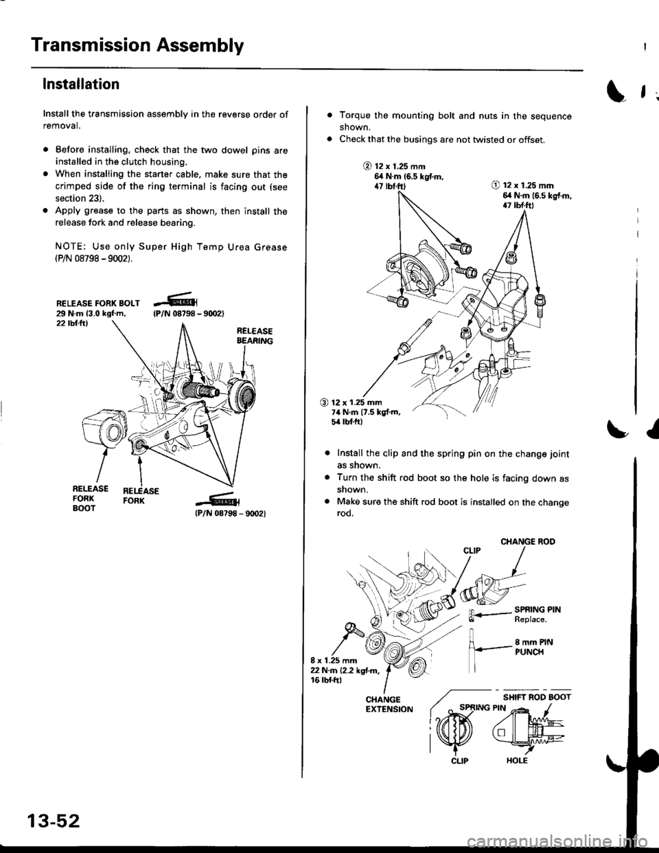
Install the transmission assembly in the reverse order of
removal.
. Before installing, check that the two dowel pins are
installed in the clutch housing.
. When installing the starter cable. make sure that the
crimped side of the ring terminal is facing out (see
section 23).
. Apply grease to the parts as shown, then install the
release fork and release bearing.
NOTE; Use only Super High Temp Urea Grease(P/N 08798 -9002).
RELEASE FORK BOLT29 N.m 13.0 kgf.m,22 tbllrl
(P/N 08798 - 9rD2l
-R1
tP/N 08798 -
13-52
CLIP
L f ;
Torque the mounting bolt and nuts in the sequence
shown.
Check that the busings are not twisted or offset.
@ t2 x 1.25 mm6,t N.m 16.5 kgtm,47 lbf.ft)O t2 x 1.25 mm6,r N.m (6.s kg{.m,17 tbf.ft)
O 12 x 1.25 mm7ilNm17.5kgf.m,5it lbt ft)
I
Install the alip and the spring pin on the change joint
as snown.
Turn the shift rod boot so the hole is facing down as
snown.
Make sure the shift rod boot is installed on the changerod.
CHANGE ROO
FL.- SPRING PINll heptace,
8 mm PINPUNCH
/ "*,*
lo,iD(
CHANGE ./EXTENSfoN ( ^ st
l?rffi
l\K