Page 635 of 2189

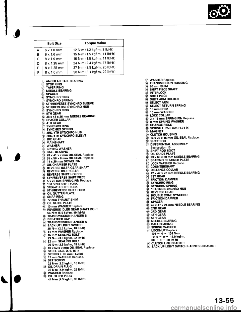
Bolt SizeTorque Value
cn
E
F
6x1.0mm
6x1.0mm
8 x 1.0 mm
8 x '1.25 mm
8 x 1.25 mm
8 x 1,0 mm
12 N.m (1.2 kgnm, 8 lbf'ft)
15 N.m (1.5 kgf'm, 11 lbf ft)
15 N.m (l.5 kgf.m, 11 lbift)
24 N'm (2.4 kgim, 17 lbift)
27 N.m (2.8 kgf.m,20 lbf'ft)
30 N.m (3.1 ksf m. 22 lbift)
5i WASHER Replace.6 TRANSMrssioN HouslNG!9 80 mm SHIM@ SHIFT PIECE SHAFT(6' INTERLOCK@ sHrFr PECE6} SHIFT ARM HOLDER@ seucr nnrvtI9 SELECT RETURN SPRING
@ 10 mm SHIM6, 10 mm WASHER@ LOCK COLLARi6sl 3 x l5 mm SPRING PIN Replace.t0 8 mm SPRING WASHERA) CHANGE PIECEll SPRING L.25.6 mm (1.01 in)'' MAGNET?4) CLUTCH HOUSINGta. 14 x 25 x 16 mm OIL SEAL Replace.A sHrFT BooO D|FFERENT|aL ASSEMBLYSee section 15iIO SHIFT ROD BOOT6 OIL GUIDE PLATE@ 33 x 60 x 20 mm NEEDLE BEASINGO BEARING RETAINER PLATElD LocK WASHER Replace..0 couNTERSHAFIA DISTANCE COLLAR6 & x 4I x 22 mm NEEDLE BEARING6. 1sr GEAR@ FRICTION DAMPERO SYNCHRO RING.d SYNCHRO SPRING@ 1ST/2ND SYNCHRO HUB..9i. REVERSE GEARC) DOUBLE CONE SYNCHROO FRICTION DAMPERS SPACER6 T2 x TI x 24 mm NEEDLE BEARING(!' 2ND GEAR61 3RD GEARiD 4TH GEAR@ 5TH GEAR(O NEEDLE BEARING(10 BALL BEARING@ SPRING WASHERf,o LoCKNUT Replace.108 - 0- 108 N'm111.0- 0* 11.0 kgf m,80* 0- 80lbI.ft)IO CLUTCH LINE BRACKET.d BACK.UP LTGHT SWITCH HARNESS BRACKET
:!, ANGULAR BALL BEABING:2, STOP RING:3] TAPER RING..-I NEEOLE BEARINGl!-- SPACERO SYNCHRO RING? SYNCHRO SPRINGE 5TH/REVERSE SYNCHRO SLEEVE...] sTH/REVERSE SYNCHRO HUB
O SYNCHBO EING.11-r sTH GEAR1A 38 x 43 x 26 mm NEEDLE BEARINGI13) SPACER COLLAR[!] /ITH GEAR.T5) SYNCHRO RING
O SYNCHRO SPRING17 3RD/4TH SYNCHRO HUB
O 3RD/4TH sYNcHRo SLEEVE
ii9 38D GEAR8I MAINSHAFT2i WASHERA SPRING WASH€R?I BALL BEARING.a4, 28 x 41 x 7 mm OIL SEAL Replace..2i 35 x 56 x 8 mm OIL SEAL Replace.t-t 14 x 20 mm DowEL PIN
.'] OIL CHAMBER PLATE
O REVERSE IDLER GEAR SHAFT.iI.., REVERSE IDLER GEAR'd REVERSE SHIFI HOLDERait srH/REVERSE sHIFT PIECE'34 5 x 22 mm SPRING PIN Replace.3' 1ST/2ND SHIFT FORK,34' 3RD/4TH SHIFT FORKi9t) srH/nevense sstrr ronx33 OIL GUTTER PLATE!' SNAP RING3d 72 mm THRUST SHIM
@ OIL GUIDE PLATE4t 10 mm WASHER Replaceti REVERSE TDLER GEAR SHAFT BoLT54 N.m {5.5 kgf m, 40lbIft)4N TBANSMISSION HANGER B43] BREATHER CAPA,J TRANSMISSION HANGER AIT' BACK-UP LIGHT SWITCH
I
25 N.m {2.5 kgl.m, 18lblftl14 mm WASHER RePlaceaO 14 mmtt 16 mm16 mm SEALING BOLT29 N.m (3.0 kgf m,22 lbf ft):4s) 32 mm SEALING BoLT25 N m 12.5 kgl m, 18 lbl'ft)40 x 62 x I mm OIL SEAL ReplaceSTEEL BALL D.5/15 iNSPRING L. 30 mm {1.2 in)12 mm WASHER Replace.SET SCREW22 N.m {2.2 kg{ m, 16 lbl ftlOIL DRAIN PLUG39 N.m {4.0 kgf m, 29lbtftlWASHER Replace.OIL FILLER PLUG4,t N.m {4.5 kgl m, 33 lblftl
.!rl00
@l
13-55
Page 644 of 2189
Shift Rod
Removal
1. Remove the shift rod boots.
2. Remove the change piece attaching bolt and thespring washer.
3, Bemove the set screw. then remove the spring andthe steel ball.
4, Remove the shift rod, then remove the changepiece,
5. Remove the oil seal.
l_
CHANGE PIECE
SPRINGL. 25.611.01 inl
STEEL(D. s/16
SPRING WASHEN
OIL SEALR€placs.
*ry
SHIFTnoDBOOTS
\,,rl
ATTACHING AOLI
SET SCREW
13-64
Page 671 of 2189
Transmission
ReassemblY
1. Install the new oil seal
2. Set the change Piece.
3. Install the shift rod
4. Install the steel ball' the spring, and the set screw'
5. Install the spring washer and change piece attach-
ing bolt.
6. Install the shift rod boots.
8x1.0mm31 N.m 13.1 kg-m,22lb-ltl
CHANGEPIECE
@:4OIL SEALReplace.SPRINGWASHER
7. Install the oil chamber Plate'
6 x '1.0 mm12 N.m (1.2 kg-m,9lb-ft|
SPRING
, /L.256fim B()(
@ / t't o'ti"l I
{zw"y-6@
q
10.
Set the spring washer and the washer'
lnstall the mainshaft, the countershaft, and the shift
fork assemblies.
NOTE: Align the finger of the interlock with the
groove in the shift fork shaft.
SHIFT FORKS
13-91
Page 677 of 2189
Gearshift Mechanism
Overhaul
NOTE:
. Inspect rubber parts for wear and damage when disassembling;
. Install the spring pin and the clip on the change joint as shown'
. Turn the shift rod boot so the hole is facing down as shown'
. Make sure the shift rod boot is installed on the shift rod'
reDlace any worn or damaged Parts.
I x 1.25 mm22 N.m 12.2 kgf.m, 16 lbf.ft)
ffi-:t't:il1ii51i?"'*,
TU
/g3i'51!Exii
V ExrENsroN
EXTENSfON ilr'eol.T
EXTENSION ENDBUSHING
hV\
EXTENSIONWASI{ER B
MOUNT -_.--_-_---
@2'
--1'>=2 -:liT.i'ff"
.o,-.o*&--ffi{---*,
v/,,/ BALL SEAT
8 x 1.25 mm22 N.m 12.2 kgf'm, 16lblftl
,@
EXTENSION ROD
SHIFT ROD
SPRING
END
BOOT
N: g sHrFr LEvER
.*rr"r,o"-tf V-oiliiSi[a
MOUNTING I --::=t SHIFT I"EVERBRAcxEr / €9-l--enr xoloen
8 x 1.2s mm :-,rro""a,ii-ri- ri.z rsr.-, -.Q u
16 tbf.ft) ,,,.
,rar-aoa*,"o "u, / E ,",t.ruaa
Replace.6x1.0mm9.8 N.m ('1.0 kgt'm,7 tbr.ftt
8x22mmSPRING PINReplace.
IIt
@CLIP
9.a-"t't
PIN SHIFT ROD/
ZW
€lt#-,\
HOLE
13-97
Page 1036 of 2189
Driveshafts
Inspection
Driveshaft Boot
Check the boots on the driveshaft for cracks, damage,
leaking grease and loose boot bands. lf any damage is
found, replace the boot and boot bands,
Loose Splines
Turn the driveshaft by hand and make sure the splines
and joint are not excessively loose. lf any damage is
found, replace the inboard joint.
Twisied or Cracked
Make sure the driveshaft is not twisted or cracked.
Reolace it if necessarv.
DRIVESHAFT
BOOT BANDS
1.
Removal
Loosen the wheel nuts slightly.
Raise the front of the vehicle, and support it with
safety stands in the proper locations (see section 'l).
Remove the wheel nuts and front wheels.
Drain the transmission fluid (see section 13 or 14).
Raise the locking tab on the spindle nut, then
remove the nut.
Remove the selJ-locking nut and flange bolts.
FLANGE BOLT10 x 1.25 mm
(cont'd)
16-3
1.
Page 1037 of 2189

Driveshafts
Removal (cont'd)
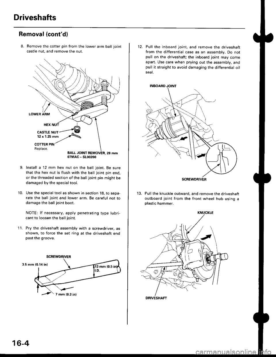
8. Remove the cotter pin from the lawer arm ball joint
castle nut. and remove the nut.
Install a 12 mm hex nut on the ball joint. Be sure
that the hex nut is flush with the ball joint pin end,
or the threaded section of the ball joint pin might be
damaged by the special tool.
Use the special tool as shown in section 18, to sepa-
rate the ball joint and lower arm. Be careful not to
damage the ball joint boot.
NOTE: lf necessary, apply penetrating type lubri,
cant to loosen the ball joint.
Pry the driveshaft assembly with a screwdriver, as
shown, to force the set ring at the driveshaft endpast the groove.
10.
11.
3.5 mm
07MAC - SL00200
SCREWDRIVER
16-4
12. Pull the inboard joint, and remove the driveshaft
from the differential case as an assembly. Do notpull on the driveshaft; the inboard joint may come
apart. Use care when prying out the assembly, andpull it straight to avoid damaging the differential oil
seat.
13. Pull the knuckle outward, and remove the driveshaft
outboard joint from the front wheel hub using aplastic hammer.
SCREWDRIVER
DRIVESHAFT
Page 1038 of 2189
t
Disassembly
lnboard Joint Side:
1. Carefully clamp the driveshaft in a vise with soft
jaws, then remove the set ring from the inboard
joint.
2. Remove the boot bands. Take care not to damage
the boot.
. lf the boot band is a locking tab type, pry up the
locking tabs with a screwdriver, and raise the
end of the band.
. It the boot band is a welded type, cut the boot
ba nd.
. lf the boot band is a crimping type, pry up the
end of the band with a screwdraver.
. lf the boot band is a double loop type, lift up the
band bend.
Locking Tab Typs
Welded Type
J
Replace.
l,
Crimping Type
Double Loop Type
Mark each roller and inboard joint to identify the
locations of rollers and grooves in the inboard joint.
Then remove the inboard joint on the shop towel.
Be careful not to drop the rollers when separating
them from the inboard ioint.
INBOARD JOINTCheck splines for wear or damage,Check inside bore for wear.Inspect for cracks.
(cont'd)
16-5
Page 1039 of 2189

Driveshafts
Disassembly (cont'dl
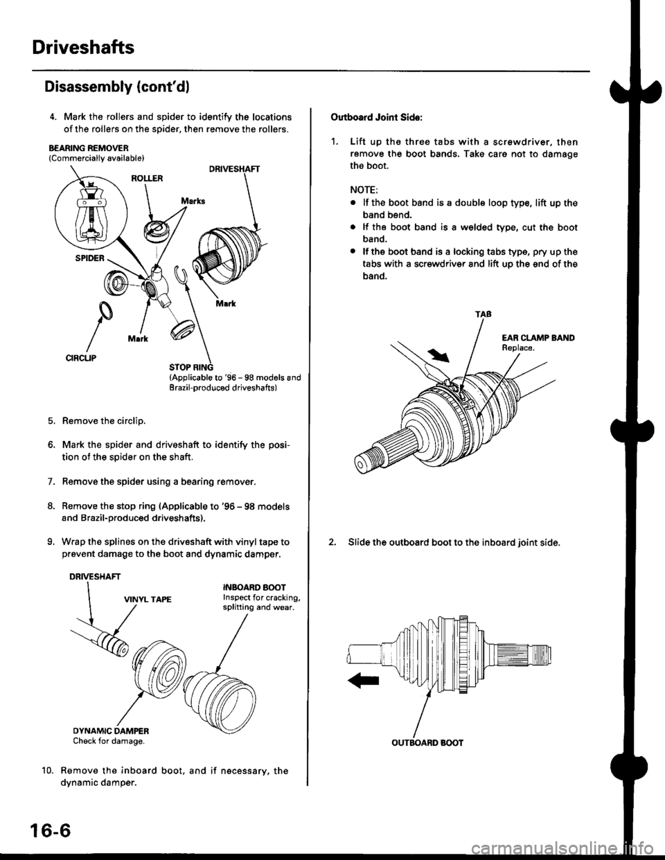
4. Mark the rollers and spider to identify the locations
of the rollers on the sDider, then remove the rollers.
B€ARING REMOVER{Commerciallv available}
STOP RING(Applicable to '96 - 98 modols andErazil-produced driveshafts)
Remove the circlip.
Mark the spider and driveshaft to identify the posi-
tion ot the spider on the shaft.
Remove the spider using a bearing remover.
Remove the stop ring (Applicable to '96 - 98 models
and Brazil-produced driveshafts).
Wrap the splines on the drivsshaft with vinyl tape to
prevent damage to the boot and dynamic damper.
DRIVESHAFT
1.
VINYL TAPE
DYNAMIC DAMPERCheck for damage.
Remove the inboard
dynamic damper.
INBOARO AOOTInspect for cracking,splitting and wear.
16-6
boot, and if necessary, the
Outboard Joint Side:
1. Lift up thc three tabs with a screwdriver, then
remove the boot bands, Take care not to damage
the boot.
NOTE:
. lf the boot band is a double loop type, lift up the
band bend.
. lf the boot band is a welded type, cut the boot
band.
. lfthe boot band is a locking tabs type, pry up the
tabs with a scr€wdriv€r and lift uo the snd of the
band.
2. Slide the outboard boot to the inboard ioint side.
TAB
OUTBOABD BOOT