Page 1476 of 2189
Troubleshooting
Schematic Symbols
BATTERY
E
@
GROGroLrnd terminal
II_d:
UNDComponent ground
II_..'-
FUSE
--cn-.e
COIL, SOLENOID
r{r
tql'|
CIGARETTE LIGHTER
A
lrl
P
RESISTOR
I
f
VARIAELE RESISTOR
ilH
THERMISTOR
c
IGNITION SWITCH
-fo o.t-
BULB
+
HEATEB
At-l
F
MOTOR
0
PUMP
H
CIRCUIT BREAKER
I
r
Yr
T
HORN
+
DIODE
+
SPEAKER, BUZZER
D
Mast
Y
ANTt:f\,NATRANSISTOR lTrl
II
SWITCH (ln niNormally open
I
/F\t tL I\Y/
I
rrdal positionlNormally closed'*i."n
@
I
LIGHT EMITTINGDIODE ILEDI
A+,
TT
RELAY lln noNormally opon relay
| ....--1'rl*r
til
t "t^f
fmal poaitionlNormally closed relay
ffl-+- |
lrl
lrl
fff
CONDENSER
I
T
CONNTInput
V
I
:CTIONOutput
J
CONNECTOR
*>-
'l!
REED SWITCH
A
tftl
Y
Page 1664 of 2189
Stereo Sound System
Window Antenna Wire Test
1. Wrap aluminum foil around the tip of the tester
probe as shown.
Touch one tester orobe to the window antenna ter-
minal near, and move the other tester probe along
the antenna wires to check that continuity exists.
WINDOW ANTENNA
23-194
OPEN
Window Antenna Wire Repair
NOTE: To make an effective repair, the broken section
must be no longer than one inch.
1. Lightly rub the area around the broken section with
fine steel wool, then clean it with alcohol.
2. Carefully mask above and below the broken portion
of the window antenna wire with cellophane tape.
CELLOPHANETAPE
Using a small brush, apply a heavy coat of silver
conductive paint extending about 1/8" on both
sides of the break, Allow 30 minutes to dry.
NOTE| Thoroughly mix the paint betore use.
Check for continuity in the repaired wire.
Apply a second coat of paint in the same way. Let it
dry three hours before removing the tape.
Page 1674 of 2189

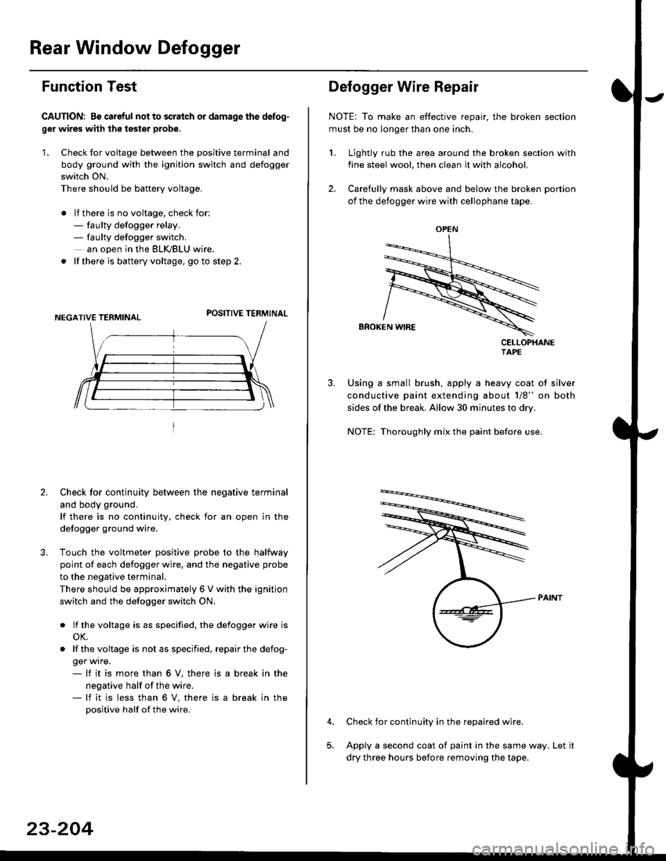
Rear Window Defogger
Function Test
CAUTION: Bs careful nol to scralch or damage the defog-
ger wires with the tester probe,
'1. Check for voltage between the positive terminal and
body ground with the ignition switch and defogger
switch ON.
There should be banery voltage.
. lf there is no voltage, check for:- faulty defogger relay.- faulty defogger switch.
an ooen in the BLK,/BLU wire.
. lf there is battery voltage, go to step 2.
POSITIVE TERMINAL
2. Check for continuity between the negative terminal
and body ground.
lf there is no continuity, check for an open in the
defogger ground wire.
Touch the voltmeter positive probe to the halfway
point of each defogger wire, and the negative probe
to the negative terminal.
There should be approximately 6 V with the ignition
switch and the defogger switch ON.
. lf the voltage is as specified. the defogger wire is
oK.
. lf thevoltage is not as specified, repairthe defog-
ger wrre.- lf it is more than 6 V, there is
negative half of the wire.- lf it is less than 6 V, there is
positive half of the wire.
a break in the
a break in the
23-204
OPEN
?
Defogger Wire Repair
NOTE: To make an effective repair, the broken section
must be no longer than one inch.
1, Lightly rub the area around the broken section with
fine steel wool, then clean it with alcohol.
2. Carefully mask above and below the broken portion
of the defogger wire with cellophane tape.
CELLOPHANETAPE
Using a small brush, apply a heavy coat of silver
conductive paint extending about 1/8" on both
sides of the break. Allow 30 minutes to dry.
NOTE: Thoroughly mix the paint before use.
Check for continuity in the repaired wire.
Apply a second coat of paint in the same way. Let it
dry three hours before removing the tape.
Page 1818 of 2189
How To Use This Manual
The next few pages describe how this manual is organized. They also
explain what kind of information the manual contains, what that
informalion means, and how to use it to troubleshoot electrical problems.
Circuit schematics break the entire electrical system into individual
systems, like the Low Fuel lndicator Light on the nelit page.
Only electrical components that work together are shown together,
so you won't be distracted by unrelated wires.
Explanations of the abbreviations and svmbols used in the schematics
begin on page [Fl. You'll need to know what they mean before you can use
a schematic effectively.