Page 36 of 2189

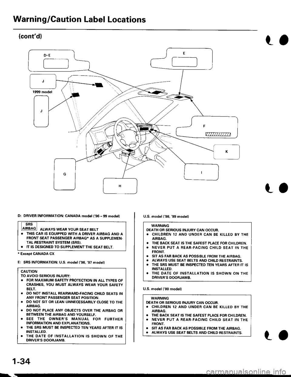
Warnin g/Gaution Label Locations
(cont'dl
to
-==-J
_)F
v7777m7na
ro
* Except CANADA CX
E: SBS INFORMATION: U.S. model ('96. '97 model)
CAUTIONTO AVOID SERIOUS INJURY:. FOR MAXIMUM SAFEW PROTECTION IN ALL TYPES OFCBASHES, YOU MUST ALWAYS WEAR YOUR SAFETYBELT.. DO NOT INSTALL REARWARD-FACING CHILD SEATS lNANY FRONT PASSENGER SEAT POSITION.. DO NOT SIT OR LEAN UNNECESSARILY CLOSE TO THEAIRBAG.. DO NOT PLACE ANY OBJECTS OVER THE AIRBAG ORBETWEEN THE AIRSAG AND YOURSELF.o SEE THE OWNER,S MANUAL FOB FURTHERINFORMATION AND EXPLANATIONS.. THE SRS MUST BE INSPECTED TEN YEASS AFTER IT ISINSTALLED,. THE DATE OF INSTALI-ATION IS SHOWN OF THEDRIVER'S DOORJAMB.
U.S. model ('00 modelI
WARNINGDEATH OR SERIOUS INJURY CAN OCCUR,. CHILDREN 12 AND UNDER CAN BE KILLED BY THEAIRBAG.. THE BACK SEAT IS THE SAFEST PLACE FOR CHILOREN.. NEVER PUT A REAR-FACING CHILD SEAT lN THEFRONT.o SIT AS FAR BACK AS POSSIBLE FROM THE AIRBAG.o ALWAYS USE SEAT BELTS AND CHILD RESTRAINTS.
D: DRIVER INFORMATION: CANADA mod6l l'96 - gtt modell
ALWAYS WEAR YOUR SEAT BELT. THIS CAR IS EOUIPPED WITH A DRIVER AIRBAG AND AFRONT SEAT PASSENGER AIRBAG' AS A SUPPLEMEN-TAL RESTRAINT SYSTEM ISRSI.. IT IS OESIGNED TO SUPPLEMENT THE SEAT BELT,
U.S. model l'98, 39 model)
WARNINGOEATH OR SERIOUS INJURY CAN OCCUR.. CHILDREN 12 AND UNOER CAN BE KILLED BY THEAIREAG.. THE BACK SEAT IS THE SAFEST PLACE FOR CHILDREN.o NEVER PUT A BEAR.FACING CHILD SEAT IN THEFRONT.. SIT AS FAR BACK AS POSSIBLE FROM THE AIRBAG.. ALWAYS USE SEAT BELTS AND CHILD RESTRAINTS.. THE SRS MUST BE INSPECTED TEN YEARS AFTER IT ISINSTALLED,. THE DATE OF INSTALLATION IS SHOWN ON THEDRIVER'S DOORJAMB.
1-34
ro
Page 67 of 2189

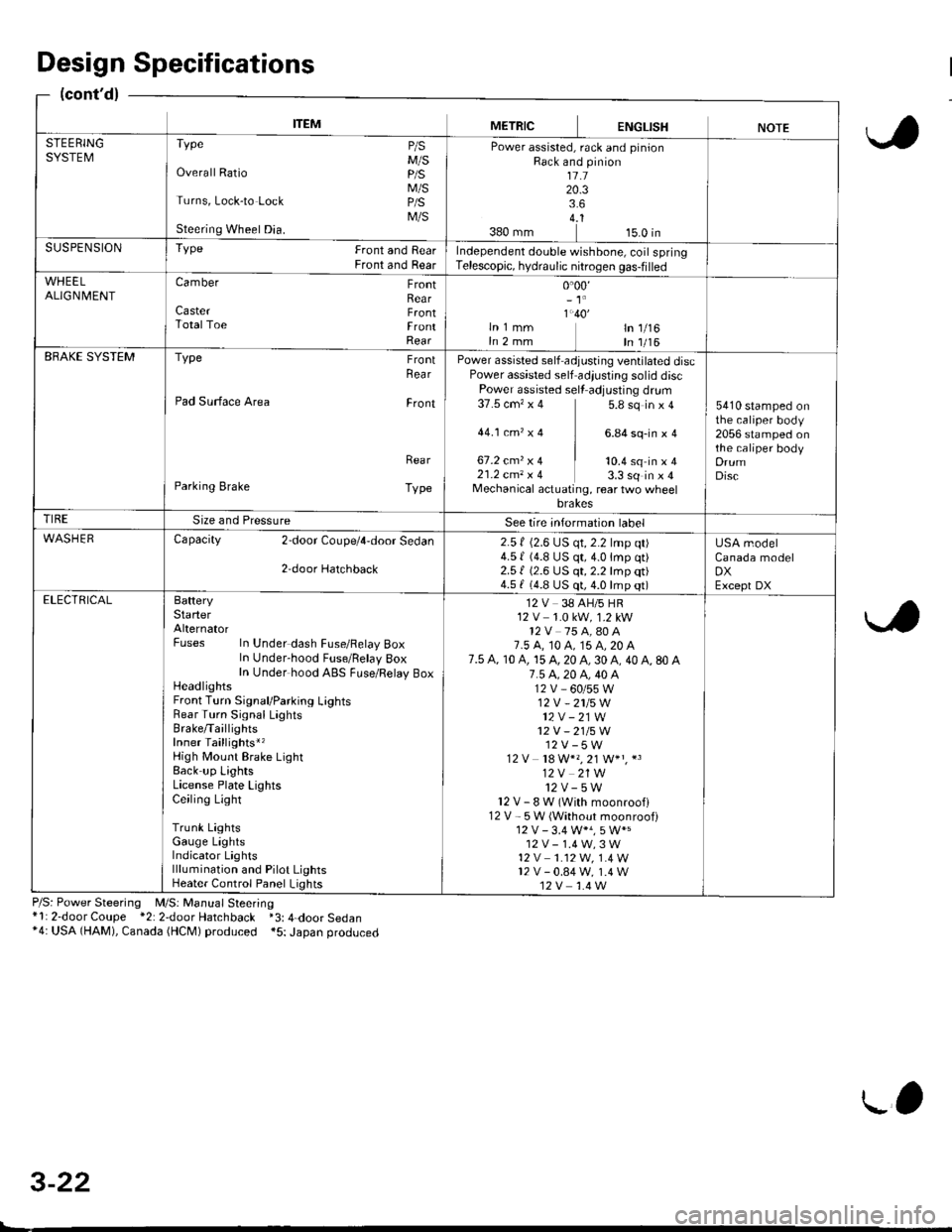
ITEMMETRICENGLISHNOTESTEERINGSYSTEMTvpe P/sM/SOverall Ratio p/S
M/STurns, Lock-to Lock p/S
M/SSteering Wheel Dia.
Power assisted, rack and pinionRack and pinion1l.120.33.64..1380 mm 15.0 inSUSPENSIONTYPe Front and RearFront and RearIndependent double wishbone, coil springTelescopic, hydraulic nitrogen gas-filled
WHEELALIGN| 4ENTCamber FrontRearCaster F.ontTotalToe FrontRear
0.00,- 't'
1.40'ln 1 mm ln 1/16In 2 mm In 1/16EBAKE SYSTEMType FrontRea r
Pad Surface Area Front
Rea r
Parking Brake Type
Power assisted self adjusting ventilated discPower assisted self adiustjng solid discPower assisted sell adjusting dr!m37.5 cm'�x 4 5.8 sq in x 4
44.1ctn,x4 ] 6.84sq-inxa
67.2 cmz x 4 | to.+ sq in ' I21.2 cm, x 4 3.3 sq in x 4Mechanical actuating, rear two wheelbrakes
5410 stamped onthe caliper body2056 stamped onthe caliper bodyDrumDisc
TIRESize and PressureSee lire intormation label
WASHERCapacity 2door Coupe/4,door Sedan
2,door Hatchback
2.5 f (2.6 LJS qt, 2.2 lmp qt)4.5 | (4.8 US qt,4.0lmp qt)2.51 (2.6 US qt, 2.2 lmp qt)4.5 f (4.8 US qt, 4.0 lmp qt)
USA modelCanada modelDXExcept DXELECTRICALBafteryStarterAlternatorFuses In Under dash Fuse/Felay BoxIn Under-hood Fuse/Belay 8oxIn Under hood ABS FLrse/Relay BoxHeadlightsFront Turn Signal/Parking LightsRear Turn Signal LaghtsBrake/TaillightsInner Taillights*,High Mount Brake LightBack up LightsLicense Plate LightsCeiling Light
Trunk LightsGauge LightsIndicator Lightslllumination and Pilot LightsHeater Control Panel Lights
12 V 38 AH/5 HR12 V 1.0 kW, 1.2 kW12V 75 A,80 A7.5 A, t0 A, 15 A, 20 A7.5 A, 10 A, 15 A, 20 A, 30 A, 40 A, 80 A7.5 4.20 A, 40 A12V_60/55W12V -2115W
12V - 21W12V - 21/5W12V-5W12 V 18 W*" 21 W+" *3
12V 21W12v-5wl2V-8W(Withmoonroofl12 V - 5W (Without moonroof)
12V-1.4W,3W't2 v 1.12W. 1.4 W12v-0.84w, 1.4 W12V 1.4 W
Design Specifications
(cont'd)
P/S: Power Steering M/S: Manual Steering*l: 2-door Coupe *2: 2door Hatchback *3: 4-door Sedan*4: USA (HAM), Canada (HCM) produced *5: Japan produced
3-22
L'
Page 445 of 2189

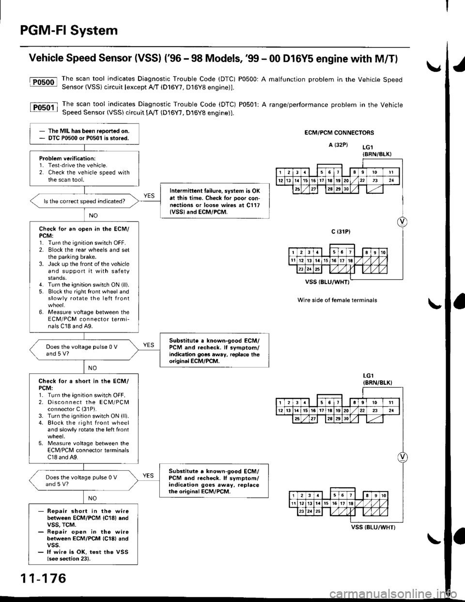
PGM-FI System
Vehicle Speed Sensor (VSSI ('96 - 98 Models,'99 - 00 D16Y5 engine with M/Tl
@The scan tool indicates Diagnostic Trouble Code (DTC) P0500: A malfunction problem in the Vehicle SpeedSensor (VSS) circuit Iexcept A!/T (D16Y7, D16Y8 engine)1.
The scan tool indicates Diagnostic Trouble Code (DTC) P0501: A range/performance problem in the VehicleSpeed Sensor (VSS) circuit [A,rT {D16Y7, D16Y8 engine)].
ECM/PCM CONNECTORS
A {32P} LG.t
VSS IBLU/WHT}
Wire side ot temale terminals
LGI(BRN/8LK}
The MIL has been reDorted on.DTC P0500 or P0501 is stored.
Problem verification:1- Test drive the vehicle.2. Check the vehicle speed withthe scan tool.
Intermittent tailure, system is OKat this time. Check tor Door con-nections or loose wires at C117{VSSland ECM/PCM.
ls the correct speed indicated?
Check for an open in the ECM/PCM:1. Turn the ignition switch OFF.2. Elock the rear wheels and setthe parking brake.3. Jack up the front of the vehicleand support it with safetystands.4. Turn the ignition switch ON (ll).
5. Block the right tront wheel andslowly rotate the left front
6, Measure voltage between theECM/PCM connector termi-nals C18 and A9.
Subslitute a known-good ECM/PCM and recheck. lf symptom/indic.tion goes away, replace theorisinal ECM/PCM.
Does the voltage pulse 0 Vand 5 V?
Check tor a short in ihe ECM/PCM:1. Turn the ignition switch OFF.2. Disco n n ect the ECM/PCMconnector C (31P).
3. Turn the ignition switch ON {ll).4. Block the right front wheeland slowly rotate the left front
5. Measure voltage between theECM/PCM connector terminalsC18 and A9.
Substitute a known-good ECM/PCM and recheck. lI symptom/indication goes away. replacethe original ECM/PCM.
Does the voltage pulse 0 Vand s V?
- Repair short in the wirebetwGen ECM/PCM {C18} endvss, TcM.- Repair open in the wirebetween ECM/PCM {Cl8} andvss.- lf wire is OK, test the VSSlsee section 23).
{BRN/BLK}
239l0lt
121611t8t9202321
2A2930
c {31P}
I38191o
tl12ialr5i6l10./
I2356a9l011
12l3l5t61tl8t920222a
27202930
12910
t2l13l.l7I l,/ 1,/231r.lslt., ),rlL
VSS {BLU/WHT}
11-176
Page 1231 of 2189
l}
e\
Body ('96 modell
Doors
Front Door Index (4D) ...20-2
Rear Door Index {4Dl .....20-8
Door fndex lzDl3Dl .......20-14
Emblems
f nstallation 20-118
Exterior
Component Location Index ............... 20-93
*Frame Repair Chart .......... 20-120
* Interior
Component Location Index ............... 20-58
Mirrors
Mirror Rep|acement .................. ......... 20-24
Mirror Holder/Gover Replacement ... 20-25
Rearview Mirror Reolacement .......... 20-25
Moonroof
lndex .......... .....................20-50
Opener Cable/Opener and Latch/
Wiper and Washer
Component Location Index .......... ...,. 20-107
Seats and Seat Belts
Gomponent Location Index .......... ..... 20-73
Sub-frame ....20-119
Windshield, Rear Window and Ouarter Glass
Index .......... .....................20-26
Body {'97 modell
Body ('98 modell
Body ('99 modell
Body ('00 model)
20-123
20-131
20-135
20-141
It
Page 1232 of 2189
Doors
Front Door lndex
,ID:
WEATHERSTRIP
POWER WINDOWswtTcH
ffitr6-
fud-@a,
Ef
Adjustment, page20-23
DOORPROTECTOR
OOOR POCKET
r^r f i'I I ) t\' \-!
20-2
J$--"**^
Page 1250 of 2189

Doors
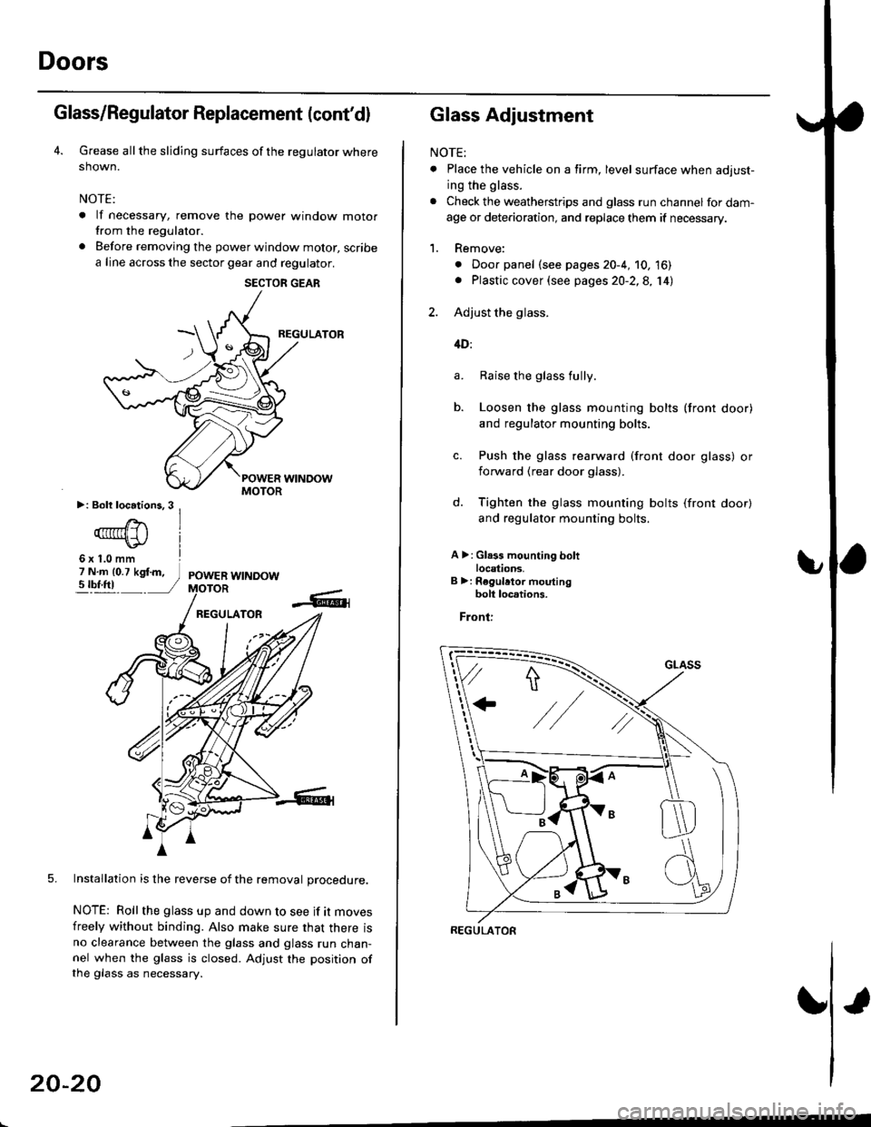
Glass/Regulator Replacement (cont'dl
Grease all the sliding surfaces of the regulator where
shown.
NOTE:
. lf necessary, remove the power window motorfrom the regulator.
. Before removing the power window motor, scribe
a line across the sector gear and regulator.
REGULATOR
5. Installation is the reverse of the removal orocedure.
NOTE: Roll the glass up and down to see if it moves
freely without binding. Also make sure that there isno clearance between the glass and glass run chan-nel when the glass is closed. Adjust the position ofthe glass as necessary.
SECTOR GEAR
20-20
Glass Adjustment
NOTE:
. Place the vehicle on a firm, level surface when adjust-
ing the glass.
. Check the weatherstrips and glass run channel for dam-
age or deterioration, and replace them if necessary.
1. Remove:
. Door panel (see pages 20-4, 10, 16). Plastic cover (see pages 20-2,8, 14)
2. Adjust the glass.
4D:
Raise the glass fully.
Loosen the glass mounting bolts (front door)
and regulator mounting bolts.
Push the glass rearward (front door glass) or
iorward (rear door glass).
Tighten the glass mounting bolts (front door)
and regulator mounting bolts.
A >: Gl.3s mounting boltlocations.B >: Regulrtor moutingbolt loc.tions.
Front:
a.
b.
d.
REGULATOR
Page 1251 of 2189
b
GLASS
REGULATOR
+"+
J\
e. Loosen the front channel mounting bolts (front
door) or rear channel mounting bolt lrear
ooor,,
f. Lower the glass.
g. Push the front or rear channels against the
glass, then tighten the mounting bolts.
>: Front and rearchannel mountingbolt locations
Front:
\
Rear:
2DI3D:
b.
Raise the glass as far up as possible, and hold
it against the glass run channel.
Loosen the roller guide bolts, and adjust the
glass so it is parallel with the glass run channel.
GLASS RUNCHANNEL
ROLLER GUIDE BOLTS
(cont'd)
20-21
Page 1252 of 2189
Doors
Glass Adjustment {cont'd)
c. Tighten the roller guide bolts.
d. Loosen the front channel bolts.
e. Lower the glass.
f. Push the front channel against the glass, then
tighten the mounting bolts.
MOUNTINGBOLT
3. Check that the glass moves smoothly.
4. Raise the glass fully and check for gaps.
5. Check the glass operation.
NOTE: Check that the glass contacts the glass run
channel evenly.
WEATHERSTRIP
GLASS
U
-\,
20-22
6. Check for water leaks.
Spray water over the roof and on the sealing area
as shown.
NOTE:
. Adjust the water pressure as shown.
. Do not squeeze the tip of the hose.
0.5 m {1.6ft)
HOSE
Attach the plastic cover, then install the door panel
(see pages 20 4, 10, 16).
Install the regulator handle so it points forward and
up at a 45 degree angle with the glass closed.
Forward -
1.
HOSE
300 mm {11.8 in)