Page 2027 of 2189
Keyless Receiver Unit Troubleshooting
lf a faulty keyless receiver unit has one of the symptoms below, turn to the page listed and follow the
appropriate troubleshooting procedure. lf the symptom seems related to an input problem, or is not covered
by the troubleshooting procedures, do the Input Tests on page 130-6. Refer to the circuit schematic on pages
1 30-2 and 130-3 as needed.
Symptom Index
Keyless Entry Does Not Work In Any Mode
Ceiling Light Does Not Come On When The Doors Are Unlocked
WithTheTransmitter ....
Doors Do Not Unlock Or Lock With The Transmitter . . . .
Horn Does Not Sound With The Transmitter "Beeo" Feature On
Horn Does Not Stop Sounding .......
Input Tests
Page 130-8
Page 130-9
Page 130-1 0
Page 130-11
Page 130-11
Page 130-11
Page 130-6
.1,
Page 2028 of 2189
Power Door Locks (cont'd)
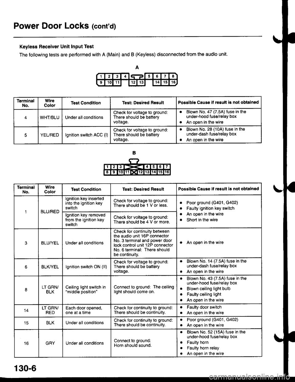
Keyless Receiver Unit Input Test
The following tests are pertormed with A (Main) and B (Keyless) disconnected from the audio unit.
TerminalNo.WireColorTest ConditlonTest: Desired RasultPossible Cause it resull is not obtained
4WHT/BLUUnder all conditionsCheck for vollage to ground:
There should bs batteryvoltage.
aBlown No. 47 (7.5A) tuse in the
under-hood fuss/relay box
An open in the wireo
5YEUREDlgnition switch ACC (l)Check lor voltage to ground:
Th€re should be battery
voltage.
aBlown No. 28 (10A) fuse in the
underdash fusg/relay box
An open in the wirea
TerminalNo.WireColorTest CondiiionTest: Desired ResultPossible Cause if rssult i3 not obtalned
BLU/RED
lgnition key insertedinto the ignition key
switch
Check for voltage to ground:
There should bs 1 V or less.aPoor ground (G401, G402)
Faulty ignition key switch
An open in the wire
Short in the wire
a
a
algnition key r€moved
trom the ignition key
switch
Check lor voltage to ground:
There should be 4 V or more.
3BLUI/ELUnder all conditions
Check for continuity betweenthe audio unit 16P connectorNo- 3 terminal and power doorlock control unit 12P connsctorNo. 6 terminal: There should
be continuity.
I An open in the wire
6BLK/YELlgnition switch ON (ll)Check for voltage to ground:
Thers should be batteryvollage.
. Blown No. 14 (7.5A) fuse in the
under-dash fuse/relay box
. An open in the wire
8LT GRN/BLKCeiljng light switch in"middle position"Connect to ground: The ceilinglight should come on.
aBlown No. 43 (7.5A) fuse in the
undsr-hood fuse/relay box
Blown ceiling light bulb
Faulty ceiling light
An open in the wire
a
a
o
14LT GRN/REDEach door oponed,one at a timeCheck for continuity to ground:
There should be continuity.
aFaulty door switch
An open in lhe wirea
tcBLKUnder all conditionsCheck for continuity to ground:
There should b€ continuity.
aPoor ground (G401, G402)
An open in the wirea
16GRYUnder all conditionsConn€ct to ground:
Horn should sound.
. Blown No.52 (15A) fuse in the
under-hood tuse/relay box
. Faulty horn
. Faulty horn relay
. An open in the wire
130-6
Page 2030 of 2189
Power Door Locks (cont'd)
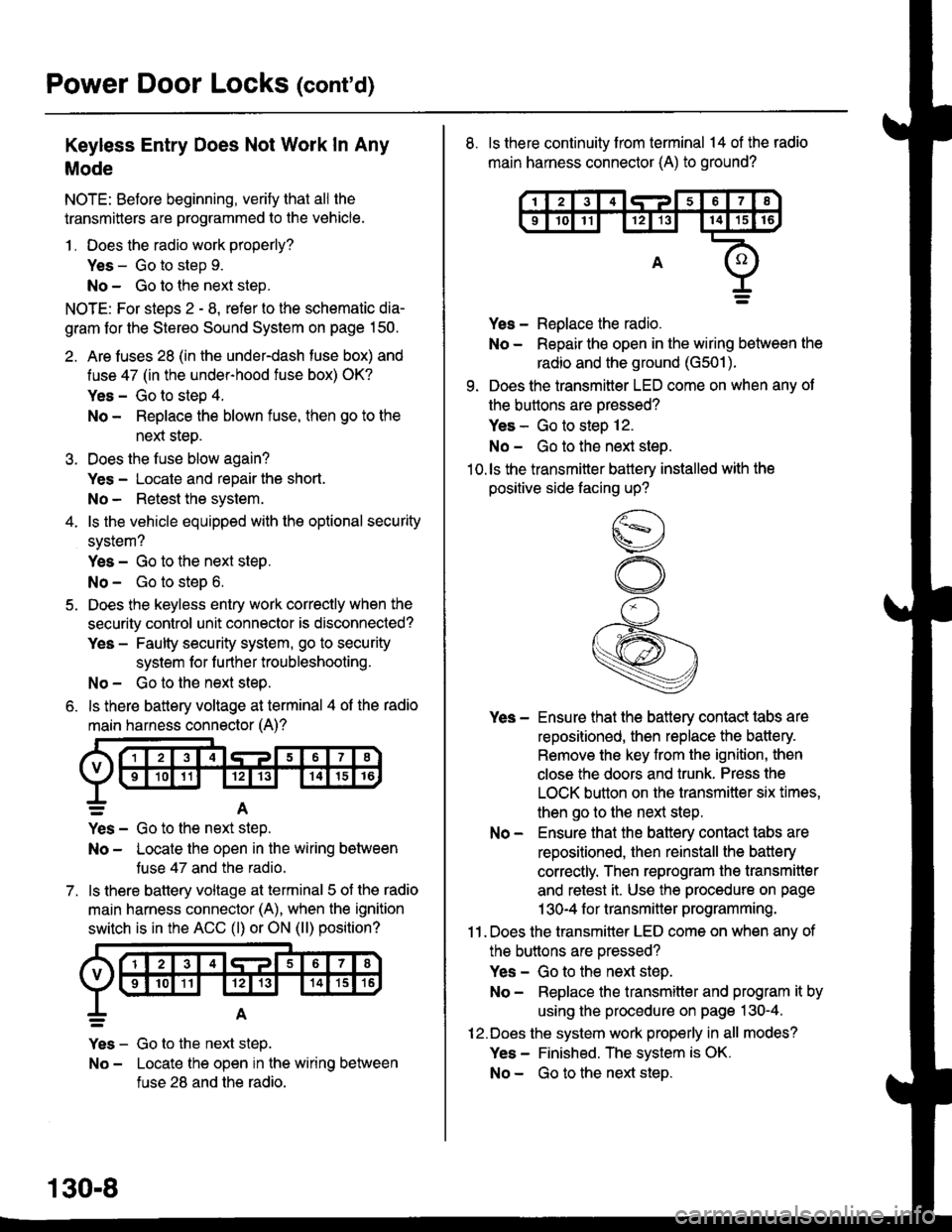
Keyless Entry Does Not Work In Any
Mode
NOTE: Before beginning, verify that all the
transmitters are programmed to the vehicle.
1 . Does the radio work properly?
Yes - Go to step 9.
No - Go to the neld step.
NOTE: For steos 2 - 8. refer to the schematic dia-
gram for the Stereo Sound System on page 150.
2. Are fuses 28 (in the under-dash fuse box) and
fuse 47 (in the under-hood fuse box) OK?
Yes - Go to step 4.
No - Replace the blown fuse, then go to the
nen steo.
3. Does the fuse blow again?
Yes - Locate and repair the short.
No- Retest the system.
4. ls the vehicle equipped with the optional security
system?
Yes - Go to the next steP.
No - Go to steD 6.
5. Does the keyless entry work correctly when the
security control unit connector is disconnected?
Yes - Faulty security system, go to security
system for f urther troubleshooting.
No - Go to the next step.
6. ls there battery voltage at terminal 4 of the radio
main harness connector (A)?
7.
=A
Yes - Go to the nen step.
No - Locate the open in the wiring between
tuse 47 and the radio.
ls there battery voltage at terminal 5 of the radio
main harness connector (A), when the ignition
switch is in the ACC (l) or ON (ll) position?
Yes - Go to the next step.
No - Locate the open in the wiring between
fuse 28 and the radio.
130-8
8. ls there continuity from terminal 14 of the radio
main harness connector (A) to ground?
Yes - Replace the radio.
No - Repair the open in the wiring between the
radio and the ground (G501).
9. Does the transmitter LED come on when any ot
the buttons are oressed?
Yes - Go to steo 12.
No - Go to the next steo.'10.ls the transmitter battery installed with the
positive side facing up?
Yes - Ensure that the battery contact tabs are
repositioned, then replace the battery.
Remove the key from the ignition, then
close the doors and trunk. Press the
LOCK button on the transmitter six times,
then go to the next step.
No - Ensure that the baftery contact tabs are
repositioned, then reinstall the batlery
correctly. Then reprogram the transmitter
and retest it. Use the procedure on page
1 30-4 f or transmitter programming.
11 . Does the transmitter LED come on when any of
the buttons are oressed?
Yes - Go to the next step.
No - Replace the transmitter and program it by
using the procedure on page 130-4.
12.Does the system work properly in all modes?
Yes - Finished. The system is OK.
No - Go to the next steD.
Page 2031 of 2189
\,113. Recheck with a known good transmitler
reprogrammed to the vehicle. Does the system
work properly in all modes?
Yes - Replace the transmitter and program it by
using the procedure on page 130-4.
No - ReDlace the radio.
\lr
\
Ceiling Light Does Not Come On When
The Doors Are Unlocked With The
Transmitter
NOTE: The vehicle must have a tactory radio installed.
1 . ls the ceiling light switch in the center position?
Yes - Go to the nexl steo.
No - Reposition the ceiling light switch and
retest.
2. Does the ceiling light come on with the ceiling
light switch in the ON position?
Yes - Go to the next step.
No - Repair the ceiling light circuit.
3. Does the transmitter LED come on when anv of
the buttons are oressed?
Yes - Go to the next step.
No - Check the transmitter battery, then retest.
lf the ceiling light still does not work, go to
the next steD.
4. Recheck with a known good transmitter
reprogrammed to the vehicle. Does the system
work properly in all modes?
Yes - Replace the transmitter and program it by
using the procedure on page 130-4.
No - Go to the ne)d steo.
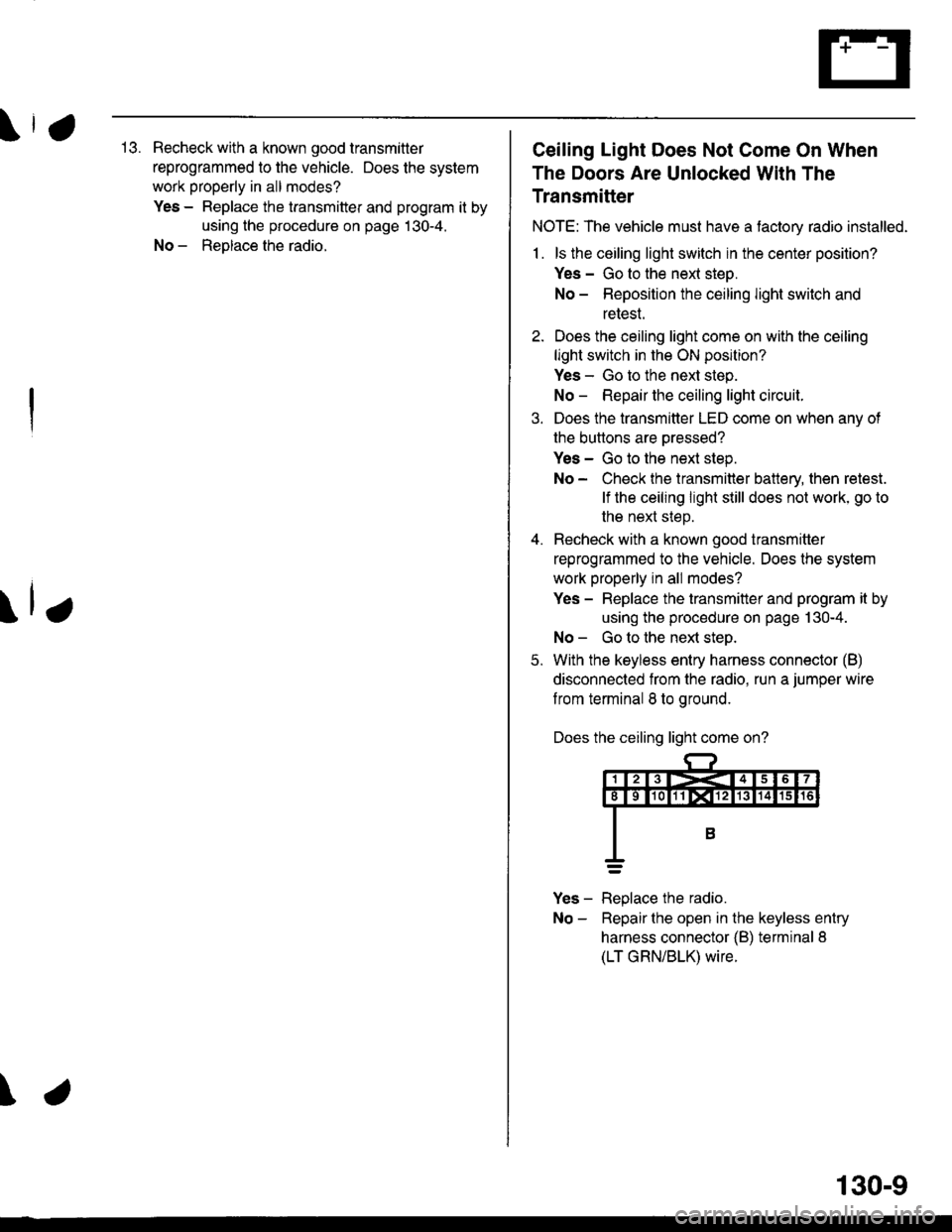
5. With the keyless entry harness connector (B)
disconnected from the radio. run a jumper wire
f rom terminal 8 to ground.
Does the ceiling light come on?
Yes - Replace the radio.
No - Repairthe open in the keyless entry
harness connector {B) terminal 8
(LT GRN/BLK) wire.
130-9
Page 2032 of 2189
Power Door Locks (contd)
Doors Do Not Unlock Or Lock With
The Transmitter
1. Do the door's unlock and lock when usinq the
driver's door lock switch?
Yes - Go to the next step.
No - Repair the power door lock system.
2. Does the transmitter LED come on when anv of
the buttons are oressed?
Yes - Go to the next steo.
No - Check the transmitter battery, then retest.
It lhe doors still do not unlock or lock with
the transmitte( go to the next step.
Recheck with a known good transmitter
reprogrammed to the vehicle. Does the system
work properly in all modes.
Yes - Replace and program the transmitter,
then retest. Use the procedure on page
1 30-4 f or transmitter programming.
No- Gotothe next step.
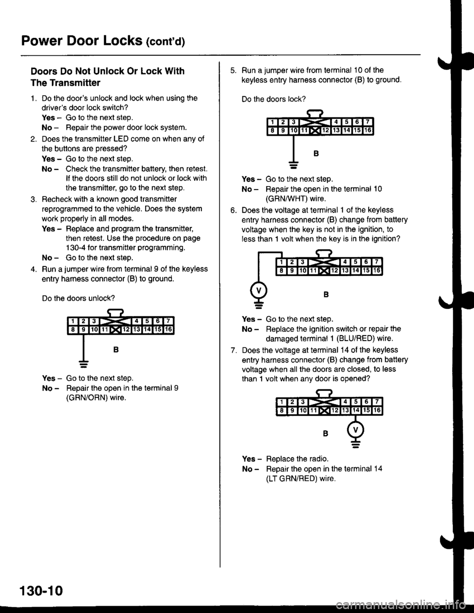
Run a jumper wire from terminal I of the keyless
entry harness connector (B) to ground.
Do the doors unlock?
Yes - Go to the next steD.
No - Repair the open in the terminal 9
(GRN/ORN) wire.
130-10
5. Run a jumper wire from terminal 10 ol the
keyless entry harness connector (B) to ground.
Do the doors lock?
ves - Go to ttie next steo.
No - Repair the open in the terminal 10
(GRN/vVHT) wire.
Does the voltage at terminal 1 of the keyless
entry harness connector (B) change from battery
voltage when the key is not in the ignition, to
less than 1 volt when the key is in the ignition?
7.
Yes - Go to the next step.
No - Replace the ignition switch or repair the
damaged terminal 1 (BLU/RED) wire.
Does the voltage at terminal 14 of the keyless
entry harness connector (B) change from battery
voltage when all the doors are closed, to less
than 1 volt when any door is opened?
Yes - Replace the radio.
No - Repair the open in the terminal 14
(LT GRN/RED) wire.
Page 2033 of 2189
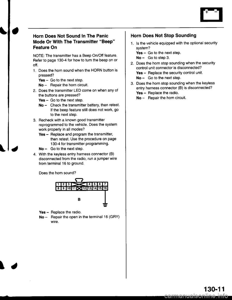
a
Horn Does Not Sound In The Panic
Mode Or With The Transmitter "Beep"
Feature On
NOTE: The transmitter has a Beep On/Off feature.
Refer to page 130-4 for how to tum the beep on or
off.
1. Does the horn sound when the HORN button is
oressed?
Yes - Go to the next steD.
No - Repair the horn circuit.
2. Does the transmittor LED come on when any of
the buttons are pressed?
Yes - Go to the next step.
No - Check the transmitter battery then retest.
ll the beep feature still does not work, go
to the next steo.
3. Recheck with a known good transmitter
reprogrammed to the vehicle. Does the system
work properly in all modes?
Yes - Replace and program the transmitter,
then retest. Use the procedure on page
1 30-4 f or transmitter programming.
No - Go to the next step.
4. With the keyless entry harness connector (B)
disconnected from the radio, run a.iumper wire
f rom terminal 16 to ground.
Does the horn sound?
Yes - Reglace the radio.
No - Repair the open in the terminal 16 (GRY)
wire.
\
Horn Does Not Stop Sounding
1. ls the vehicle equipped with the optional security
system?
Yes - Go to the next step.
No - Go to step 3.
Do€s the horn stop sounding when the security
control unit connector is disconnected?
Yes - Replace the security control unit.
No- Go to the next step.
Does the horn stop sounding when the keyless
entry harness connector (B) is disconnected?
Yes - Reolace the radio.
No - Reoair the hom circuit.
130-11
Page 2034 of 2189
Power Door Locks
- '99-'00 Models with Keyless Entry
@
i-f?G;.-----l
i ?f*""t:::", i
L-,H-i{*q-J
UNDER-DASHFUSE/RELAYBOX
8 Y C419
vtEW49
SeeHOrns
15
Horncontrol
Grgund
lgnltioninputDooropeninput
K€yswitchInpul
Lighlstlashcontrol
17
ALK
c447
vtEw 5a
'12
LT GFN/RED
See GroundDistribution,page I +6,
YI
IF--.--.r-G401
I
3
ALU/f,EO
!r.lFN' z sEcuglw t5REOSYSTEMtsb'*nii'cro* =2
a, o"nt"ao 1lvlEw 58
(Not
(oPTroN) c447See HeadlightSwitch
C415 STEERINGPHora 6a LOCKVlEtt\/ 14 PHO|O 71
lgntlion KaySYrftchClosed with keyin ignition.
LT GRN/FED
LT GFN/REDSee lgnitionKey Reminder
UNDER-DASHFUSE/RELAYBOX
ALU/IVITT
a9
GFN
'14
GRN
130-12
Page 2035 of 2189
I YEI/BEO
c57o , 5PHOfO 99V\EW 5 ' YEL/BED
c6?4 : 1PHOfAgs , YEUFED
I WHT/FED
c674 i zPHoro 95 i wrvneoc570 , a',;f,tr?"n l-1"1/1.9
I
I
9
WIIT/GRN
f*-.l'il
TryJ
UNDER.HOOOFUSE/RELAYBOX
c557
vlEw 62
c654c351
vlEW 31FRONT
aaa
! ".u".o
!t
+
See PowerDistribution,page 1S12.
PASSENGER'SDOOR LOCKACTUATOR
c654
c557
. vtEw 62
't8
9
GRN/OBN
1
GBN/ONN
19
GRN/OFN
KEYLESSDOORLOCKCONTROLUNIT
WHT/FED
12c556
vlEw 61BLU/BED
;;;oTYEL
BLUAVHT
aLU/'$/HT
4
ALUMHT
(?
***
[J
BLU/FED't5
WHT/REO
c634PHOfa 92
DRIVER'SoooRLOCKACTUATORDRIVER'SDOORLOCKswtTcH
DOORLOCKKNOB
c634PHO|A 92
BLK
BLK"iI-.
l: cssr
Battsrv UnloclvlockingJt ' otttputUnlocKlockoutpul
Look Unlock/lockinput outputUnbck LockInput input
fff
LJ-T->J
wrccr I mc.
\.
130-13