1999 HONDA CIVIC vacuum line
[x] Cancel search: vacuum linePage 39 of 2189

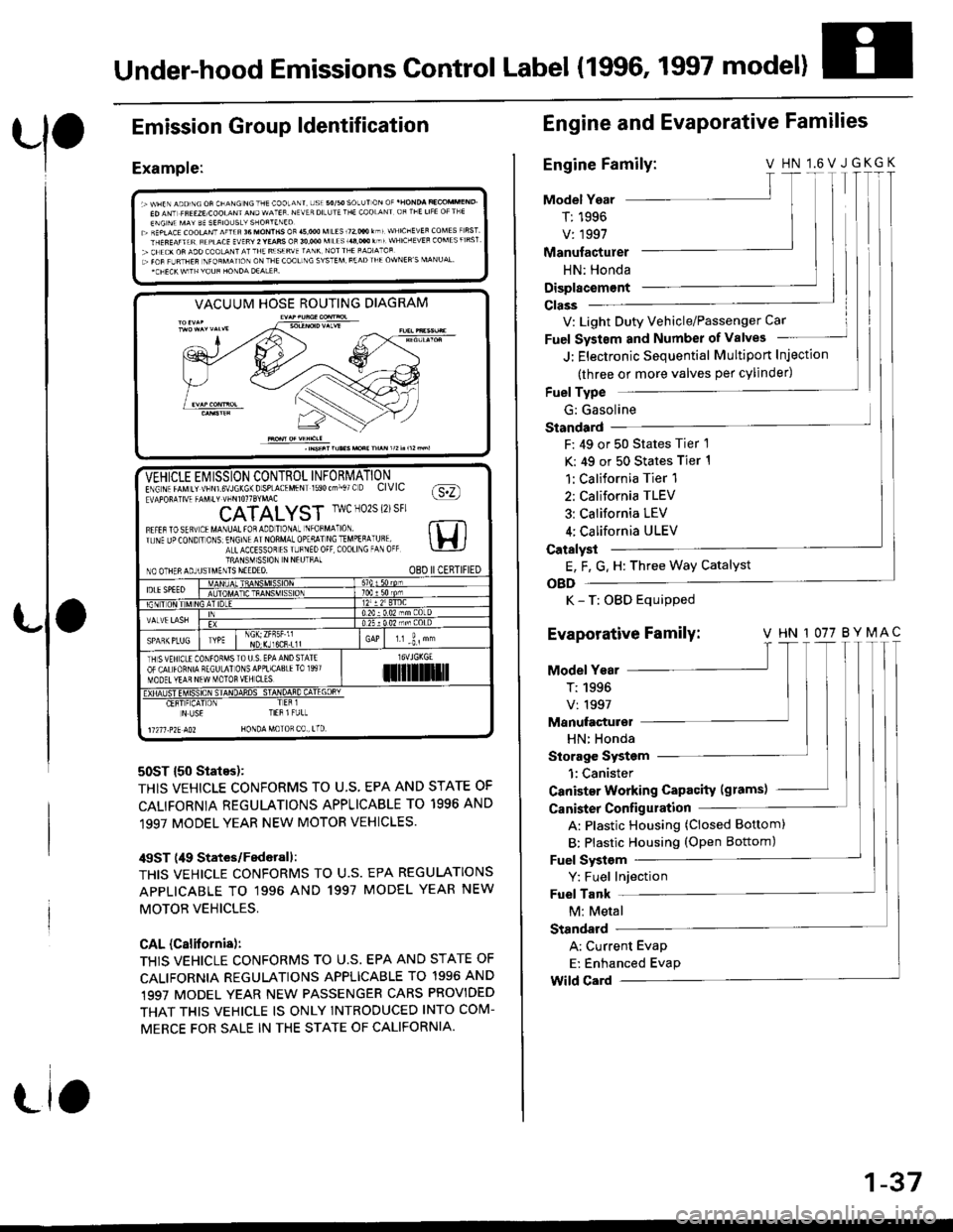
Under-hood Emissions Control Label (1996, 1997 model)
Emission
Example:
Group ldentification
VACUUM HOSE ROUTING DIAGRAM
50ST {50 States):
THIS VEHICLE CONFORMS TO U.S, EPA AND STATE OF
CALIFORNIA REGULATIONS APPLICABLE TO 1996 AND
1997 MODEL YEAR NEW MOTOR VEHICLES.
/$ST (49 States/Federall:
THIS VEHICLE CONFORMS TO U.S. EPA REGULATIONS
APPLICABLE TO '1996 AND 1997 MODEL YEAR NEW
MOTOB VEHICLES,
CAL (Calitornis):
THIS VEHICLE CONFORMS TO U.S. EPA AND STATE OF
CALIFORNIA REGULATIONS APPLICABLE TO 1996 AND,1997 MODEL YEAR NEW PASSENGER CARS PROVIDED
THAT THIS VEHICLE IS ONLY INTROOUCED INTO COM-
MERCE FOR SALE IN THE STATE OF CALIFORNIA.
-VEHICLE Ei/ ISSION CONTROL INFORMATIONE\G\. rrMrr vtsNrs\JLK6\Dsp-A(.MFN 590(--,. O CIVIC fa:n!APOF!]V4 -AV.t' !-rirorrSrMAc \Y:/
CATALYST IwcN02S{2)sFr
Fl.tarostq! tMA\uAttoaaooTo\a- \'oFM^ ro rt Tlr. \F Jo(O\D ' O\S E\Gr\l AINOnMA-OolqllNCTMoEqA Uql lH ia-LACCESSoT rS r-F\Eo0F C00ll\G -A 0( \-!-lJTRANSM1SSION N NEUTFAINO OTHERAOJUSIMENTS NEEDEO. O8D IICERTIFIED
IDLESPEEOATDC
NDr(Jl6CR.L1lr.r -i, "
TH SVEH CLE CONfOFMSTO U S. EPA AND STATEOF CALfORNIA RECULAI ONSAPPLICA8IElO 1997MOOET YEAR NEW MOTOR VEH CL'Silil]]lrl
Er!4#_"E!!ifl 4q!sq+HT-q4E!rL
N US€ TIEB l FULL
11211 .?2E AO2 HONDA MoTOR C0 , tTD
Engine and EvaPorative Families
Engine Family:V HN l.6VJGKGK
Model Year
T: 1996
V: 1997
T I
T|I
Manufacturer
HN: Honda
Displacem€nt
V: Light Duty Vehicle/Passenger Car
Fuel Systsm and Number of valves
J: Electronic Sequential Multiport Injection
(three or more valves per cylinder)
Fuel Type
G: Gasoline
Standard
F: 49 or 50 States Tier 1
K: 49 or 50 States Tier 1
1:California Tier 1
2: California TLEV
3: California LEV
4; California ULEV
Catalyst
E, F, G. H: Three Way Catalyst
OBD
K - T: OBD Equipped
Evaporative Family: v HN 1077 BYMAc'|T
Model Year
T:1996 |V:1997 lManufacturel
HN: Honda
Storage System
1:Canister
Canister Working Capacity (grams)
Canister Configulation
A: Plastic Housing (Closed Bottom)
B: Plastic Housing (oPen Bottom)
Fuel Systsm
Y: Fuel Injection
Fuel Tank
M: Metal
Standard
A: Current Evap
E: Enhanced Evap
Wild Card
1-37
Page 270 of 2189

!
Fuel and Emrsslons
SoecialToofs .....,...."..,. 11-2
Component Locations
lndex ....................., ......... 11-3
Svstem Description
Vacuum Connections ................,,..,.. ......... 11-12
Electrical Connections ...............,.,.,... ....... 11-29
System Connectors ........,.,.,.......................... 1 1-51
Troubleshooting
Troubleshooting Procedures ................. .. 11-81
Engine Control Module/PowertrainControl Module TerminalAfiangement ....,.,..... 11-88
Diagnostic Trouble Code Chart .................,., 11.97
How to Read Flowcharts .,.......................... . 11-103
PGM-Fl System
System Description ...... 11-10,1
Troubleshooting Flowcharts
Engine Control Module/PowertrainContlol Module ........ 11-107
Manitold Absolute Pressure Sensor .....'. . ... 11-115
fntake Air Temperatuie Sensor ..... . . ., . 11'121
Engine Coolant Temperatuae Sensol ........., 11-128
Throttle Position Sensor ...................,........... 11-132
Primary Heated Orygen Sensor (Sensor 1l ... 11-139
Secondary Heated Oxygen Sensor(Sensor 21.................................................... 1 1-153
Heated Oxygen Sensor Heater ...................,. 11-157
Fuel Supply System ...... 11-164
Random Mislire ......., ..11-166
Misfire Detected in One Cylindsr ................. 11-167
Knock Sensor .,.,............ 11-170
CKP/TDC/CYP Sensor ................................... 11'172
Vehicle Speed Sensor ...........,......,...,.,........... 1t-176
Barometric Pressure Sensor ...............,......... I 1-178
Electrical Load Detector,.,,............................ 1 1-179
CKF Sensor .................... 11-183
ECM/PCM Internal Circuit ............................. I 1-188
A/T Signal {TMA/TMBI .................................. I 1-189
ldle Control System
System Doscriplion ............ 11-190
Troubleshooting Flowcharts
ldle Control System ...... 11-192
ldle Air Control Va1ve .................................... I 1-19i1
Starter Switch Signal .................................... 1 1'202
Air Conditioning Signal ................................. 11'201
Ahernator FR Signal .................................... . 1 1-208
BrakeSwitch Signal ..................................... f 1"210
Power Sleering Prossure Switch Signal ......11-212
A/T Gear Position Signal ............................... 11-216
Clutch Swiich Signal ................................-.... 11-214
ldte Speed Setting . .............11-220
Fuel Supply System
Fuel Lines .,...................,.,.,.,11-221
Fuef Tube/Ouick-Connect Fittings ..........,.,........ 11 -227
System Description ....'.... 11-230
Fuel Pressure .......,.,,........... 11-230
Fuef fniectors ......................11-232
Fu€f Pressure Regulator .....,.......................'...,. 11-231
Fuef Fifter ............................11-235
Fuel Pump .............'.......'.... 11-236
PGM-FI Main Relay .............11'237
Fuel Tank ................ ....,...'.'.' 11'211
Intake Air System
System Description ....-.-.....11-243
Air Cfeaner ...........,......."". .11-211
Throttle Cable .....................11-211
Throttfe Body ........ ..'... . . .,.11-211
Fuel Iniestion Air Control System ,.,.,....-........... 11-250
Emission Control System
System Description .-..........11-252
Taifpip€ Emission ...............11-252
Three Way Catafytic Convert€r ............,.,,.,.,.,.... 11 -252
Exhaust Gas Racirculaiion System ...,.,,,,.,.,.,.,,. 11'254
Positive Crankcas€ Ventilation System .... . . .. 11-266
Evaoorative Emission Controls ..................,,..,.,. 11 -267
Page 368 of 2189

,'o
L
*:The E indicator light and the Maltunction Indicator Lamp (MlL) may come on simultaneously.*1: D16Y5 engine (CVT)"5: '96 D16Y5 engine, D16Y7 engine, D16Y8 engine (sedan).'97 D16Y5 engine, Dl6Y7 engine (coupe: KA, KC models, sedan: KA.
KC, KL (DX) models, hatchback: all models), D16Yg engjne (sedan: KA, KC models)*6: '96 D16Y8 engine (coupe),'97 Dl6Y7 engine (coupe: KL model, sedan: KL (LX) model),'97 D'16Y8 engine (coupe: all models,
sedan: KL model),'98-all models,'99-all models,'00-all models*12: Except A,,/T (D16Y7, D16Y8 enginei*13: A"/T (D16Y7, D16Y8 engine)!l*14:'97 model*16:'98 model" 17: '99 - 00 models
(cont'd)
1 1-99
DTC{MlL indication}Detoction lt€mProbable C.usePage
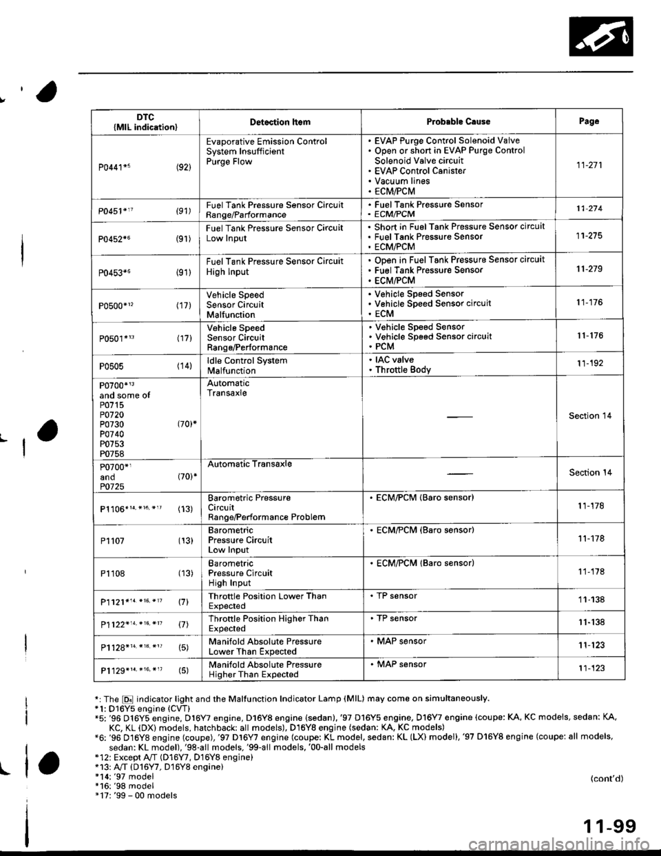
P0441*5 (92)
Evaporative Emission ControlSystem InsufficientPurge Flow
EVAP Purge Control Solenoid VaiveOpen or short in EVAP Purge Control
Solenoid Valve circuitEVAP Control CanisterVacuum linesECM/PCM
11-271
P0451'11 (91)FuelTank Pressure Sonsor CircuitRange/Parformance
. FuelTank Pressure Sensor' ECM/PCM11 274
P0452{6(9r )
Fuel Tank Pressure Sensor CircuitLow Input
Short in FuelTank Pressure Sensor circuatFuel Tank Pres$ure SensorECM/PCM
11-275
P0453*6 {91)
Fuel Tank Pressure Sensor Circuit
High Input
ODen in Fuel Tank Pressure Sensor circuit
Fuel Tank Pressure Sensor
ECM/PCM
11-219
P0500*1, (17)Vehicle SpeedSensor CircuitMalfunction
V€hicle Speed SensorVehicle Speed Sensor circuit
ECM
11-176
P0501*'3 l17l
Vehicle SpeedSensor CircuitRange/Performance
V€hicle Sp€ed SensorVehicle Speed Sensor circuitPCM
r 1- 176
P0505 (14)ldle Control Systemlvl a lfu n ctio n
. IAC valve. Throttle Body11-192
P0700*r3and some ofP0715P0720P0730 (70)*
P0740P0753P0758
AutomaticTransaxle
Section 14
P0700*1and (70)*
P0725
Automatic TransaxleSection 14
(13)Barometric PressureCircuitRange/Performance Problem
. ECM/PCM (Baro sensor)1 1-178
P1107 (13)BarometricPressure CircuitLow Input
. ECM/?CM (Baro s€nsor)11-178
P1108 (13)BarometricPressure CircuitHigh Input
. ECM/PCM lBaro sensor)1 1-178
P1121*'. *16. *'? \71Throttle Position Lower ThanExpected
. I r sensor11-138
P1122'14.*16.*n 17lThrottle Position Higher ThanExpected
. TP sensor11-'138
15)Manifold Absolute PressureLower Than Expected
. MAP sensor1 1'123
P1129*1r.*16.*"(5)Manifold Absolute PressureHigher Than Expected
. MAP sensor't1-123
Page 388 of 2189

|'Manifold Absolute Pressure (MAP) Sensor
(;gg - OO Models except Dl6Y5 engine with M/T)
The scan tool indicates Diagnostrc Trouble Code (DTC) PO1O7: A low input (high vacuuml problem in the
Manifold Absolute Pressure (MAP) sensor'
The MAp sensor converts manifold absolute pressure into electrical signals and inputs the ECM/PCM'
OUTPUTVOLTAGE
lvl3.5
3.0
2.5
2.0
1.5
1.0
0.5
0(in.Hgl GAUGEREAOING(mmHgllq, 2oo 3q, (x, 5q) 6q) 700
MAP SENSOR 3P CONNECTOR IC114)
vccltYEL/RED)
Wire sido of fomalg tormin6ls
.-l
- The MIL h'3 been reported on- OTC P0107 b stor€d.
Problem verilication:
1. Turn the ignition switch ON {ll)
2. check the N4AP with the scan
tool.
lntermittent failuro, 3Ystom is OK
at this time. Ch€ck for Poor con'
nection3 or loose wiros at C111
IMAP sonsorl and ECM/PCM.
ls approx. 101 kPa (760 mmHg,
30 in.Hg)indicated?
Ch.ck for an opcn in wit. {vCC1
linel:1. Turn the ignition switch OFF
2. Disconnect the MAP sensor
connector.3. Turn the ignition switch ON (ll).
4. Measure voltage between the
MAP sensor connector No. 1
terminal and No 2 terminal
Repair opsn in the wirg botween
ECM/PCM (C19) rnd MAP seGor.ls there approx. 5 V?
(To page 11-120)
{cont'd)
1 1-1 19
Page 390 of 2189

!Manifold Absolute Pressure (MAPI Sensor -
i;idlga lil;dels,'99 - 00 Dl6Y5 ensine with M/T)
ll
The scan tool indicates Diagnostrc Trouble code (DTC) Po108: A high voltage (low vacuum) problem in the
Manifold Absolute Pressure (MAP) sensor.
MAP SENSOR 3P CONNECTOR ICl11}
MAPIRED/GRNI
JUMPER WIRE
Wire side ol female terminals
vcclIYEL/RED)
ECM/PCM CONNECTOR D (16PI
MAP(RED/GRN)
sG1(GRN/WHT)
Wire side of female terminals
(cont'd)
11-121
The MIL has been reported on
OTC m108 is stolod.
Problem vetitication:
1. Start the engine. Hold the
engine at 3,000 rPm with no
load (in Park or neutral) until
the radiator fan comes on, then
let it idle.
2. Check the MAP with the scan
tool.
lntormittent lailure, sFtom k OK
.t thb time. Chock lor Poor con'
nections or loorg wires at Cll'l
|MAP sensorl snd ECM/PCM.
ls 101 kPa (760 mmHg,30 0 in.Hg)
or higher indicated?
Check tor an open in the MAP
36nSOt:1. Turn the ignition switch OFF
2. Disconnect the MAP sensor
3P connector.3. Install a jumper wire betlveen
the MAP sensor 3P connector
terminals No 3and No 2.
4. Turn the ignition switch ON (ll).
5. Check the MAP with the scan
tool.
ls 101 kPa (760 mmHg, 30 0 in.Hg)
or higher indicated?
Check for an open in wire (SG1
line):1. Remove the iumper wire.
2. Measure voltage between the
MAP sensor 3P connector te.
minals No. 1 and No 2
Rapai. open in the wito batwoen
ECM/PCM (D12) .nd MAP !en.or.ls there approx. 5 V?
Check for an oPon in the wiie
(MAP linel:1. Turn the ignition switch OFF.
2. Connect the ECM/PCM con-
nector terminals D3 and D12
with a iumPer wire.
3. Turn the ignition switch ON (ll).
4. Check the MAP with the scan
tool.
Repair opon in the wiles bstlt oon
ECM/PCM (D3l and MAP 3oGor.ls 101 kPa (760 mmHg, 30 0 in.Hg)
or higher indicated?
Substituto a known'good ECM/
PCM and rochock. ll normal MAP
is indicated, replace tho original
ECM/PCM.
JUMPER WIRE
lr,
Page 391 of 2189

PGM-FI System
Manifold Absolute Pressure (MAPI Sensor
11-122
('99 - 00 Models except D16YS engine with M/T) (contd)
The scan tool indicates Diagnostic Trouble Code (DTC) P0108: A high voltage flow vacuum) problem in theManifold Absolute Pfessure (MAp) sensor,
MAP SENSOR 3P CONNECTOR (C111I
MAPIRED/GRNI
Wire side of female terminals
vcclIYEL/RED)
ECM/PCM CONNECTOR C (31PI
JUMPER WIRE
Wire side of female terminals
Tho MIL has boon rcDortod on.DTC ml 08 b stolod.
Problem verification:'1. Start the engine. Hold theengine at 3,000 rpm with noload (in Park or neutral) untilthe radiator fan comes on, thenlet it idle.2. Check the MAP with the scantoot,
Intormittent f.ilu.e, rystom is OXat thi! time. Chock tor poor con-n6ction3 or looso wirea at C111(MAP 3en.or) and tho ECM/PC-M.
ls 101 kPa (760 mmHg.30in.Hg) or higher indicated?
Check for an open in the MAPaon5('r:1. Turn the ignalion switch OFF.2. Disconnect the MAP sensor3P connector.3. Install a jumper wire betwesnthe MAP sensor 3P conn6ctorterminals No.3 and No.2.4. Turn the ignition switch ON {ll).5. Check the MAP with the scantool.
ls 101 kPa (760 mmHg, 30in.Hg) or higher indicated?
Check fo. an opcn in wiro (SGlline):1. Removo the jumper wire.2. Measure voltage between theMAP sonsor 3P connector terminals No. 1 and No.2.
Roprir opon in tha wiJo bctwoenthc ECM/FCM (C7l rnd the MApsonln t.
ls there approx. 5 V?
Chsck for an open in tho wi.e{MAP lino}:1. Turn the ignition switch OFF.2. Install a jumper wire on theECM/PCM connectors betweenC7 and C17.3. Turn the ignition switch ON (ll).4. Check the MAP with the scantool,
Repair op€n in the wir6a bstwoontho ECM/FCM (C171 and rh6 MApscnltoa.
ls 101 kPa (760 mmHg, 30in.Hg) or higher indicated?
Substituto a known-good ECM/PCM and rechcck, It normal MAPis indiceted. r.place tho originalECM/PCM.
JUMPER WIRE
--
Page 499 of 2189

Fuel Supply System
System Description
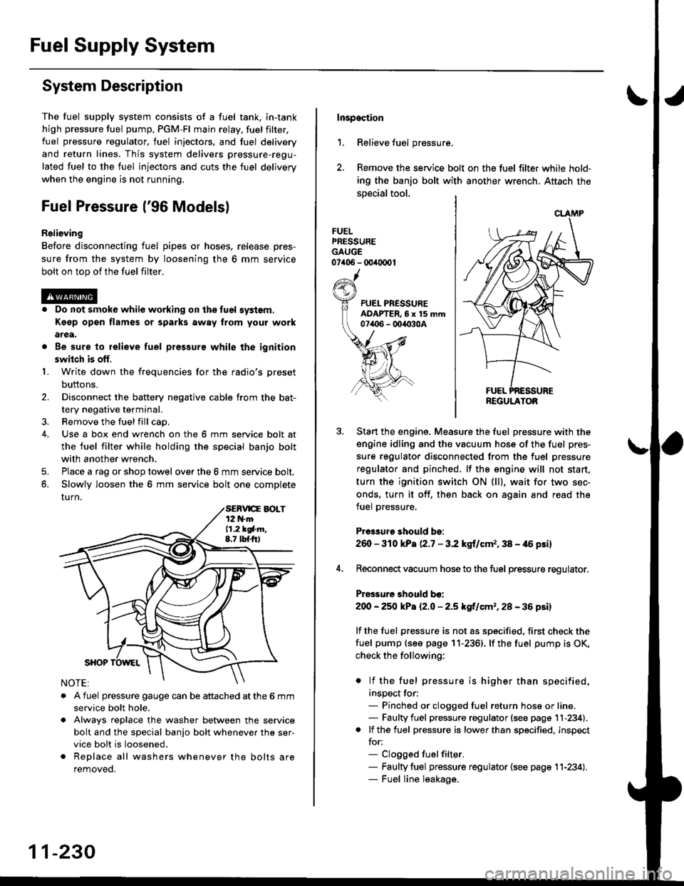
The fuel supply system consists of a fuel tank, in-tank
high pressure fuel pump, PGM-FI main relay, fuelfilter,
fuel pressure regulator, fuel injectors. and fuel delivery
and return lines. This system delivers pressure-regu-
lated fuel to the fuel injectors and cuts the fuel delivery
when the engine is not running.
Fuel Pressure l'96 Modelsl
Relieving
Before disconnecting fuel pipes or hoses, release pres-
sure from the system by loosening the 6 mm service
bolt on top of the fuel filter.
. Do not smoke whil6 working on the fuel system.
Kgsp opon flames or sparks away from youl work
area.
. Be sure to relieve fuel pressure while the ignition
switch is off.
1. Write down the frequencies for the radio's preset
buttons.
2. Disconnect the battery negative cable from the bat-
tery negative terminal.
3. Remove the fuelfill cap,
4. Use a box end wrench on the 6 mm service bolt at
the fuel filter while holding the special banjo bolt
with another wrench,
5. Place a rag or shop towel over the 6 mm service bolt.
6, Slowly loosen the 6 mm service bolt one complete
rurn.
. A fuel pressure gauge can be attached at the 6 mm
service bolt hole.
. Always reDlace the washer between the service
bolt and the special banjo bolt whenever the ser-
vice bolt is loosened.
. Replace all washers whenever the bolts are
removeo.
11-230
Inspoction
1. Relieve fuel pressure.
2. Remove the service bolt on the fuel filter while hold-
ing the banjo bolt with another wrench. Attach the
special tool.
FUELPRESSUREGAUGE07406 - 00ir0(x)1
Start the engine. Measure the fuel pressure with the
engine idling and the vacuum hose of the fuel pres-
sure regulator disconnected from the fuel pressure
regulator and pinched. lf the engine will not start,
turn the ignition switch ON (ll), wait for two sec-
onds, turn it off, then back on again and read the
fuel pressure.
Pr€3sure should bo:
260 - 310 kPa (2.7 - 3.2 kgt/cmr, 38 - 46 psi)
Reconnect vacuum hose to the fuel pressure regulator,
Pressure should bo:
200 - 25O kPa l2.O - 2.5 kgf/cm'�, 28 - 36 psil
lf the fuel pressure is not as specified, first check the
fuel pump {see page 11-2361. lf the fuel pump is OK,
check the following:
. lf the fuel pressure is higher than specified,
inspect for;- Pinched or clogged fuel return hose or line.- Faulty fuel pressure regulator (see page 11-234).. lf the fuel pressure is lower than specified, inspect
for:- Clogged fuelfilter.- Faulty fuel pressure regulator {see page 11-234).- Fuel line leakage.
REGULATOB
Page 500 of 2189

tJFuel Pressure {'97 and later Models)
ReliGving
Before disconnecting tuel pipes or hoses, release pres-
sure from the system by loosening the 12 mm banjo
bolt on top of the fuel filter.
@o Do not smoke whilo working on the fuel sy3lom.
Ksgp op€n flames or sparks away tlom Your work
arga.
. Be sure to relieve fuel pressule while the ignition
swhch is off.
1. Write down the frequencies for the radio's preset
buttons,
2. Disconnect the battery negative cable from the bat-
tery negative terminal.
3. Remove the fuel fill cap.
Use a box end wrench on the 12 mm banjo bolt at
the fuel filter while holding the fuel filter with anoth-
er wrench.
Place a rag or shop towel over the 12 mm banio bolt.
Slowly loosen the 12 mm banjo bolt one complete
turn.
4.
I
12 mm BAtt OBOLT33 N.m (3.i1 kgf m,25 tbf.f0
NOTE: Replace all the washers whenever the 12
mm banio bolt is loosened or removed.
Inspaqtion
1. Relieve fuel pressure.
2. Remove the 12 mm banjo bolt from the fuel filter
while holding the fuel Jilter with another wrench
Attach the special tools.
3. Start the enginethe fuel Pressure with the
engine idling and the vacuum hose of the fuel pres-
sure regulator disconnected from the fuel pressure
regulator and pinched lfthe engine will not start, turn
the ignition switch ON {ll), wait for two seconds, turn
it off, then back on again and read the fuel pressure'
Pr$3uro ehould be:
excepi 816A2 sngine:
260 - 310 kPa {2'7 - 3.2 kgf/cm" 38 - {6 Fi}
B16A2 engine:
27O -32O kPa P.8 - 3'3 kgf/cm'�, '10 - 47 psi)
4. Reconnect vacuum hoso to the fuel pressure regulator'
Pre33ure 3hould be:
except B16A2 engin€:
2OO - 250 kPa {2.0 - 2'5 kgf/cm'�, 28 - 36 psi)
B16A2 engino:
210 - 260 kPa 121 - 2.6 ksf/cm'�, 30 - 37 psi)
lf the fuel pressure is not as specified, first check the
fuel pump (see page 11-236) lfthetuel pumpisoK,
check tho following:
. lf the fuel pressure is higher than specified,
inspect for:- Pinched or clogged fuel return hose or line.
- Faulty fuel pressure regulator (see page 11-
2341.
. lf the fuel pressure is lower than specified, inspect
for:- Clogged fuel filter.
- Faulty fuel pressure regulator (see page l1-
2341.- Fuel line leakage.
FUEL PRESSUREADAPTER BOLT, 12 mm
tguxt8-PD6-0101
CLAMP
REGULATOR
11-231