1999 HONDA CIVIC vacuum line
[x] Cancel search: vacuum linePage 559 of 2189

Emission Control System
Ch€ck the EVAP purge controlsolenoid valv6:1. Disconnect the 2P connectorfrom the EVAP purge controlsolenoid valve.2. Ouickly raise the engine speedto 3,000 rpm.
Insped vacuum hose routing.lf OK. roplace the EVAP purge
control solonoid valve.
Chock tor r short in the wir€
{PCS line):1. Turn the ignition switch OFF.2. Disconnect ECM/PCM connec-tor A (32P).
3- Check tor continuity betweenthe EVAP purge control sole-noid valve 2P connector termi-nal No. 2 and body ground.
Check the vacuum when hot:1. Turn the ignition switch OFF.2. Block the rear wheels and setthe parking brake.3. Jack up the lront of the vehi-cle and support it with safetystands.4. Start the engine. Hold theengine at 3,000 rpm with noload (in Park or neutrali until
the radiator fan comes on, thenlet it idle.5. Check for vacuum at the vac-uum hose with transmissionin gear (A/T in E position,
lvl/T in 1st gear) after startingthe engine.6. Ouickly raise the engine speedto 3,000 rpm.
Rooair shoft in the wire belwegnthe EVAP pulg6 control solenoidvalvs and tho ECM/PCM {A61.ls there continuity?
Substitute a known-good ECM/PCM and rech6ck. lt 3ymptom/indicrtion 90e3 rway, r6plac6 th€o.iginal ECM/FCM.
Check th€ EVAP purge controlsolenoid valve:1. Turn the;gnition switch OFF.2. Disconnect the 2P connectorfrom the EVAP purge controlsolenoid valve and warm itup to normal operating tem-perature again if necessary.3. Start the engine.4- At the harness side, measurevoltage between the EVAPpurge control solenoid valve2P connector terminal No. 1and No.2 with the transmis-sion in gear {A/T in E posi-tion, M/T in lst geari.
In3pect vacuum hoae routing.lf OK, repl.ce EVAP purge con-trol solonoid valve.ls there battery voltage?
Chock for an open in the wire(lG1 lina):At the harnoss side, measure volt-age beNveen the EVAP purge con-trol solenoid valve 2P connectorterminal No. 1 and body ground.
Repair open in the wire b€lwe€nEVAP purge contrl 3olenoid valv6and lhe No. 15 ALTERNATOR SPSENSOR 17.5 A, fu3e.
ls there battery voltage?
Evaporative Emission (EVAPI Controls (cont'dl
(From page 11-289)
(To page 11-291)
11-290
IJ
EVAP PURGE CONTROL SOLENOIDVALVE 2P CONNECTOR IC114I
PCS
IRED/YEL)
temaletermrnars
of
PCS(RED/YEL)
tGlIBLK/YEL)
{To page 11 291)
Page 561 of 2189

Emission Control System
Evaporative Emission (EVAPI Gontrols (cont'd)EVAP BYPASSSOLENOID VALVEY
(From page l1'291)
Check for a short in the wire{2WBS linel:Disconnect the 2P connector {romthe EVAP bypass solenoid valve.
Does the valve hold vacuum?
Repair short in the wire betweenEVAP bypass solenoid velve andrhe ECM/PCM {A3).
Ooes the valve hold vacuum?
Check the EVAP bvpr$ 3olenoid
1. Turn the ignition switch OFF.2. Connect ECM/PCM connectorterminal A3 and body groundwith a jumper wire.3. Turn the ignition switch ON (ll).Ch€ck lor an op.n in the wirellcl linol:1. Turn the ignition switch OFF.2. Disconnect the 2P connectorfrom the EVAP bypass sole-noid valve.3. Turn the ignition switch ON (lll.
4, Measure voltage between theEVAP bypass solenoid valve2P connector terminal No. 1and body ground.
Does the valve hold vacuum?
Repair open in the wir6 b€tw€€nEVAP purg6 control 3olanoid valveand the No. 15 ALTERNATOR SPSENSOR {7.5 A) Iuse.
Wire side ol female terminals
EVAP SYPASS SOLENOIOVALVE 2P CONNECTOR IC793}
tG1{BLK/WHT)
Wire side offemaleterminals
{To page 11 293)
11-292
(To page 11 293i
Page 563 of 2189

Emission Control System
Evaporative Emission (EVAPI Controls (cont'd)
Evaporative Emission (EVAPI Two Way Valve Testing
l'96 DIGYS engine lcoupel,'97 Dl6Y7 engine (coupe: KL
model, sedan: KL (LX) modoll,'97 Dl6Y8 engine {coup€:
alt models, sedan: KL model, '98-all modelsll:
1. Remove the fuel fill cap.
2. Remove the vapor line from the EVAP two way
valve. and connect it to a T-fitting from a vacuum
gauge and a vacuum pump as shown.
VACUUM/PRESSURE
IJ
f96 D16Y5 engine,'96 D16Y7 engine,'96 D16Y8 ongine
(sedanl,'97 D16Y5 engine,'97 Dl6Y7 engine {coupe: KA,
KC models, sedan: KA, KC, KL {DX} models, hatchback:
all modsls),'97 D16Y8 engine {sedan: KA, KC models}l:
1. Remove the fuel fill cap,
2. Remove the vapor line from the EVAP two way
valve on the fuel tank, and connect it to a T-fitting
from a vacuum gauge and a vacuum pump as
snown.
VACUUM/PRESSURE GAUGE,0 - 4 in.Hg07JAZ - 0010008VACUUMPUMP/GAUGE.0 -30 in.HgA973X-041 -XXXXX
Apply vacuum slowly and continuously while watch-
ing the gauge. The vacuum should stabilize momen-
tarily at 0.8 - 2.1 kPa (6 - 16 mmHg, 0.2 - 0.6 in.Hg).
lf the vacuum stabilizes (valve opens) below
0.8 kPa {6 mmHg, 0.2 in.Hg) or above 2.1 kPa
(16 mmHg, 0.6 in.Hg), install a new valve and retest.
Move the vacuum pump hose from the vacuum fit-
ting to the pressure fitting, and move the vacuum
gauge hose from the vacuum side to the pressure
side as shown.
Slowlv pressurize the vapor line while watching the
gauge. The pressure should be stabilize momentari
ly above 1.0 kPa (8 mmHg. 0.3 in.Hg).
. lf the pressure momentarily stabilizes (valve
opens) above '1.0 kPa (8 mmHg, 0.3 in.Hg), the
valve is OK.
. lf the pressure stabilizes below 1.0 kPa (8 mmHg,
0.3 in.Hg), install a new valve and retest.
Apply vacuum slowly and continuously while
watching the gauge. The vacuum should stabilize
momentarily at 0.7 - 2.0 kPa (5 - 15 mmHg, 0.2 - 0.6
in.Hg ).
lf the vacuum stabilizes (valve opens) below
0.7 kPa (5 mmHg,0.2 in.Hg) or above 2.0 kPa
(15 mmHg, 0.6 in.Hg), install a new valve and retest.
Move the vacuum pump hose from the vacuum fit-
'l'
4.
5.
ting to the pressure fitting, and move the
gauge hose from the vacuum side to the
side as shown.
PRESSURESIDE
Slowly pressurize the vapor line while watching the
gauge. The pressure should stabilize at 1.3 - 4.7 kPa
(0 - 35 mmHg, 0.4 - 1.4 in.Hg).
. It the pressure momentarily stabilizes (valve
opens) at 1.3 - 4.7 kPa (10 - 35 mmHg, 0.4 - 1.4
in. Hg), the valve is OK.
. lf the pressure stabilizes below 1.3 kPa (10 mmHg,
0.4 in.Hg) or above 4.7 kPa (35 mmHg. 1.4 in.Hg),
install a new valve and retest.
vacuum
pressure
GAUGE0- 4 in.Hg
T-FITTINGT-FITTING
11-294
\,
Page 564 of 2189

\
Evaporative Emission (EvAPl Two Way Valve T6ting
'99 - 00 modols:
'L Remove the fuel tank (see page 11-242).
2. Remove the vapor line {rom the EVAP two way
valve (located above the EVAP control canister), and
connect it to a T-fitting from vacuum gauge and
vacuum pumo as snown,
VACUUM/PRESSUREGAUGE0 - il in.Hg07JAZ - 001(x)08
ry(L
"*'"""_,";f1
T.FITTING
Apply vacuum slowly and continuously while watch-
ing the gauge.
The vacuum should stabilize momentarily at 0.8 -
2.1 kPa {6 - 16 mmHg, 0.2 - 0.6 in.Hg).
lf the vacuum stabilizes (valve opens) below
0.8 kPa (6 mmHg, 0.2 in.Hg) or above 2.1 kPa
(16 mmHg, 0.6 in.Hg), install a nsw valve and retest.
Move the vacuum pump hose from the vacuum fit-
ting to the pressure fitting, and move the vacuum
gauge hose from the vacuum side to the pressure
side as shown.
GAUGE,0 - 30 in.Hg4973X - (Xl -
xxxxx
J.
5. Slowly pressurize the vapor lin€ while watching the
gauge.
The pressure should be stabilize momentarily
above 1.0 kPa (8 mmHg, 0.3 in.Hg).
. lf the pressure momentarily stabilizes (valve
opens) above 1.0 kPa (8 mmHg, 0.3 in.Hg), the
valve is OK.
. ll the pressure stabilizes below 1.0 kPa (8 mmH9,
0,3 in,Hg), install a new valve and retsst.
(cont'd)
11-295
Page 1175 of 2189

Master Cylinder/Brake Booster
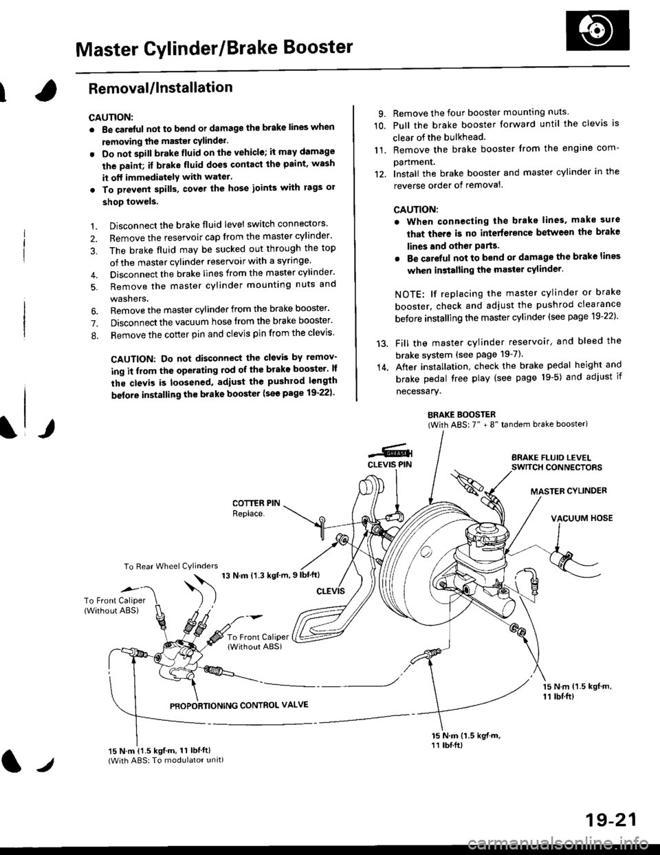
IRemovaUlnstallation
CAUTION:
. Be care{ul nol to bend or damage the brake lines when
rsmoving the mastsr cYlinder.
. Do not soill brakefluid on the vehicle; it may damage
the paint; if brake fluid does contact the paint, wssh
it off immediatelY with water'
. To prevent spill3, cover the hose ioints with rags or
shop towels.
9. Remove the four booster mountlng nuts
10. Pull the brake booster forward until the clevis is
clear of the bulkhead.
11. Remove the brake booster from the engine com-
panmenr.'12. Install the brake booster and master cylinder in the
reverse order of removal.
CAUTION:
. When connecting the brake lines. make sure
that there is no inte erence between the brake
lines and oth6r Parts.
r Be careful not to bend or damage the brake lines
when installing the master cylinder.
NOTE: lf replacing the master cylinder or brake
booster, check and adiust the pushrod clearance
be{ore installing the master cylinder (see page 19-221'
Fill the master cylinder reservoir, and bleed the
brake svstem (see Page 19-7).
After installation. check the brake pedal height and
brake pedal tree play (see page l9-5) and adjust if
necessary.
BRAKE BOOSTER(With ABS: 7" + 8" tandem brake booster)
BRAKE FLUIO LEVELSWITCH CONNECTORS
MASTER CYLINDER
VACUUM HOSE
1.
2.
3,
5.
Disconnect the brake fluid level switch connectors'
Remove the reservoir cap from the master cylinder'
The brake fluid may be sucked out through the top
of the master cylinder reservoir with a syrlnge.
Disconnect the brake lines from the master cylinder'
Remove the master cylinder mounting nuts and
washers.
\l/
6. Remove the master cylinder from the brake booster'
7. Disconnect the vacuum hose trom the brake booster'
8. Remove the cotter pin and clevis pin from the clevis'
CAUTION: Do not disconnect the clevb by remov-
ing it from the operating rod of the brako booster' lf
the clevis is loosened, adiust the pushrod length
before installing th€ brake booster (see page 19-221'
COTTER PINReplace.
To Rear Wheel Cylinders
14.
-6.4CLEVIS PIN
To Front Caliper(Without ABS)$
t'N't'ttrnt'-''
To Front CaliperlWithout ABSi
PBOPORTIONING CONTROL VALVE
15 N.m {1.5 kgl m,11 tbtft)
15 N.m {1.5 kgif.m, 11 lbtft}(With ABS: To modulator unit)lr
19-21
Page 1176 of 2189

Master Cylinder/Brake Booster
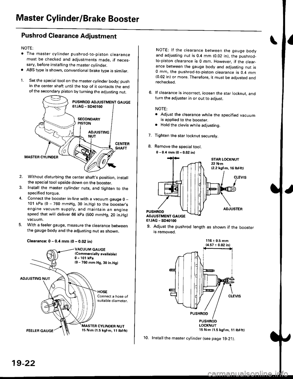
Pushrod Glearance Adjustment
NOTEr
. The master cylinder pushrod-to-piston clearancemust be checked and adjustments made, if neces_sary, before installing the master cylinder.. ABS type is shown, conventional brake type is similar.
1. Set the special tool on the master cylinde. body; push
in the center shaft until the top of it contacts the endofthe secondary piston by turning the adjusting nut.
Without disturbing the center shaft's Dosition, installthe specialtool upside down on the booster.Install the master cylinder nuts, and tighten to thespecified torque.
Connect the booster in-line with a vacuum gauge O _
101 kPa (0 - 760 mmHg, 30 in.Hg) to the booster,sengine vacuum supply, and maintain an enginespeed that will deliver 66 kpa (500 mmHg, 20 in.Hg)vacuum.
With a feeler gauge. measure the clearance Detweenthe gauge body and the adjusting nut as shown.
Clearance: 0 - 0.4 mm {0 - 0.02 in)
VACUUM GAUGE(Comm€rcially availeblel0 - 101 kPa{0 - 760 mm Hg, 30 in.Hg)
AOJUSTING NUT
FEELER GAUGE
19-22
10.
NOTE: lf the clearance between the gauge bodyand adjusting nut is 0.4 mm (0.02 in), the pushrod-to-piston clearance is 0 mm. However, if the clear_ance between the gauge body and adjusting nut is0 mm, the pushrod-to-piston clearance is 0.4 mm(0.02 in) or more. Therefore, it must be adjusted andrechecked.
6. lf clearance is incorrect, loosen the star locknut, andturn the adjuster in or out to adjust.
NOTE;
. Adjust the clearance while the specified vacuumis applied to the booster.. Hold the clevis while adjusting.
Tighten the star locknut securely.
Remove the special tool.
0 - 0.4 mm (0 - 0.02 in)
7.
ADJUSTERPUSHRODADJUSTMENT GAUGE07JAG - SD('1(x)
9. Adjust the pushrod length as shown if the boosterrs removed.
STAR LOCKNUT22 N.m{2.2 kg,f.m, 16lbtft)
11610.5 mm{{.571 0.02 in)
PUSHRODLOCKNUT15 N.m 11.5 kgf.m, 11 tbtftl
Install the master cylinder {see page l9-21).
Page 1177 of 2189

Brake Booster InsPection
FunctionalTest
1. With the engine stopped, depress the brake pedal
several times to deplete the vacuum reservoir, then
depress the pedal hard and hold it for 15 seconds lf
the pedal sinks' either the master cYlinder is
bypassing internally, or the brake system (master
cylinder. lines. modulator, proportioning control
valve, or caliPer) is ieaking.
2. Start the engine with the pedal depressed lf the
pedal sinks slightly, the vacuum booster is operating
normally. lf the pedal height does not vary, the
booster or check valve is faultY.
3. With the engine running. depress the brake pedal
lightly. Apply just enough pressure to hold back
automatic transmission creep. lf the brake pedal
sinks more than 25 mm (1.0 in.) in three minutes,
the master cvlinder is faulty. A slight change in
pedal height when the A'lC compressor cycles on
and off if normal. (The A/C compressor load
changes the vacuum available to the booster')
Leak Test
1. Depress the brake pedal with the engine running.
then stop the engine. lf the pedal height does not
vary while depressed for 30 seconds, the vacuum
booster is OK. lf the pedal rises. the booster is
faulty.
2, With the engine stopped, depress the brake pedal
several times using normal pressure When the
Dedal is first depressed, it should be low On con-
secutive applications, the pedal height should grad-
uallv rise. lf the pedal position does not vary, checK
the booster check valve.
l./
19-23
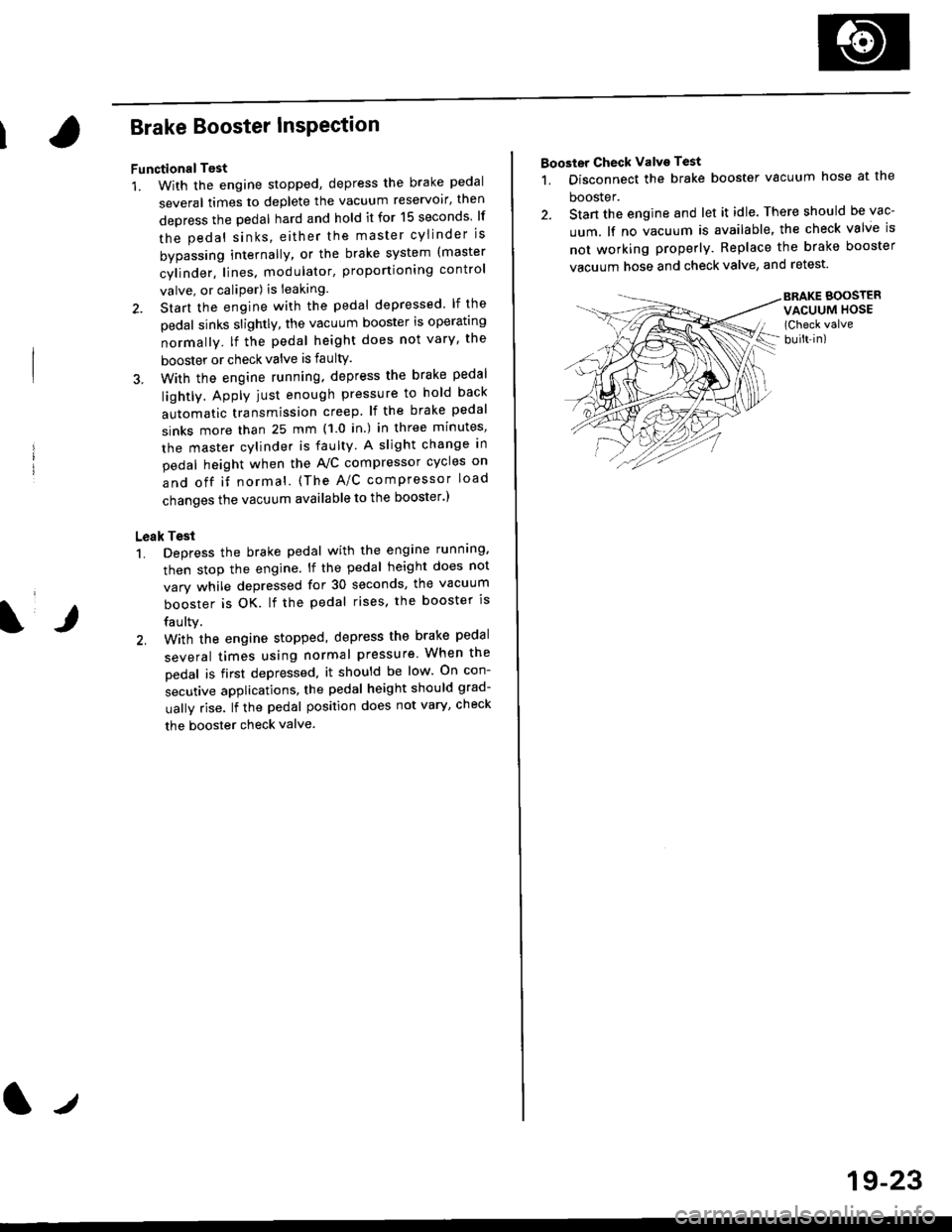
Booster Check Valve Test
1. Disconnect the brake booster vacuum hose at the
booster.
2. Stan the engine and let it idle. There should be vac-
uum. lf no vacuum is available, the check valve is
not working properly. Replace the brake booster
vacuum hose and check valve, and retest.
BRAKE BOOSTERVACUUM HOSE(Check valve
built-in)
Page 1450 of 2189

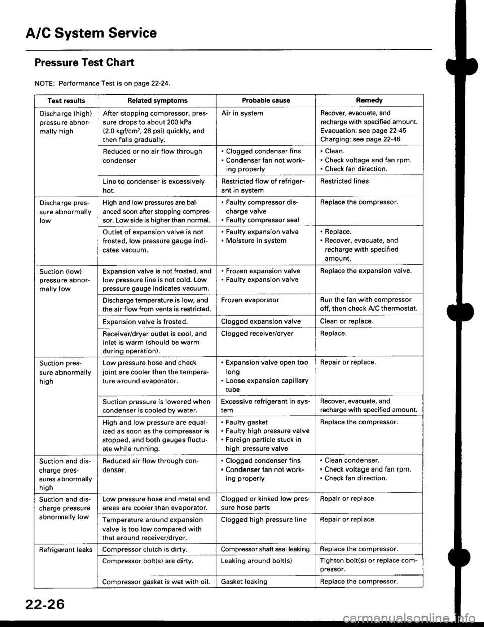
A/C System Service
Pressure Test Chart
NOTE: Performance Test is on page 22-24,
Test resultsRelated symptomsProbabl€ causeRemedy
Discharge (high)
pressure aDnor-
mally high
After stopping compressor. pres-
sure drops to about 200 kPa
{2.0 kgflcm,,28 psi) quickly, and
then falls gradually.
Air in systemRecover, evacuate, and
recharge with specified amount.
Evacuation: see page 22-45
Charging: see page 22-46
Reduced or no air flow through
condenser
. Clogged condenser fins. Condenser fan not work-
ing properly
Clean.
Check voltage and fan rpm.
Check fan direction.
Line to condenser is excessively
hot.
Restricted flow of refriger-
ant in system
Restricted lines
Discharge pres-
sure abnormally
High and low pressures are bal-
anced soon after stopping compres-
sor, Low side is higher than normal.
. Faulty compressor dis-
charge valve. Faulty compressor seal
Replace the compressor.
Outlet of expansion valve is not
frosted, low pressure gauge indi-
cales vacuum.
. Faulty expansion valve. Moisture in system
. Replace,. Recover, evacuate, and
recharge with specified
amount.
Suction (low)
pressure abnor-
mally low
Expansion valve is not frosted, and
low oressure line is not cold. Low
pressure gauge indicates vacuum.
. Frozen expansion valve. Faulty expansion valve
ReDlace the exoansion valve.
Discharge temperature is low. and
the air flow from vents is restricted.
Frozen evaporatorRun the fan with compressor
off. then check A,/C thermostat.
Exoansion valve is frosted.Clogged expansion valveClean or replace.
Receiver/dryer outlet is cool, and
inlet is warm (should be warm
during operation).
Clogged receiver/dryerReplace.
Suction pres-
sure abnormally
hig h
Low pressure hose and check
joint are cooler than the tempera-
ture around evaporator.
. Expansion valve open too
long. Loose expansion capillary
tube
Repair or replace.
Suction oressure is lowered when
condenser is cooled bv water.
Excessive refrigerant in sys-
tem
Recover. evacuate, and
recharge with specified amount.
High and low pressure are equal-
ized as soon as the compressor is
stopped, and both gauges fluctu-
ate while running.
Faulty gasket
Faulty high pressure valve
Foreign particle stuck in
high pressure valve
Replace the compressor.
Suction and dis-
charge pres-
sures abnormally
h igh
Reduced air flow through con-
denser.
. Clogged condenser fins. Condenser fan not work-
ing properly
Clean condenser.
Check voltage and fan rpm.
Check fan direction.
Suction and dis-
charge pressure
abnormally low
Low pressure hose and metal end
areas are cooler than evaporator.
Clogged or kinked low pres-
sure hose parts
Repair or replace.
Temperature around expansion
valve is too low compared with
that around receiver/dryer.
Clogged high pressure lineRepair or replace.
Refrigerant leaksCompressor clutch is diny,Compressor shaft seal leakingReplace the compressor.
Compressor bolt{s) are diny.Leaking around bolt(s)Tighten bolt(s) or replace com-
pressor.
Compressor gasket is wet with oil.Gasket leakingReplace the compressor.
22-26