1999 HONDA CIVIC Power locks
[x] Cancel search: Power locksPage 683 of 2189

One-way Clulch
The one-way clutch is positioned between the countershaft 1st gear and the park gea., with the park gear splined to the counter-
shatt, The 1st gear provides the outer race surface, and the park gear provides the inner race surface. The one-way clutch
locks up when power is transmitted from the mainshaft 1st gear to thetountershaft 1st gear. The lst clutch and gears
remain engaged in the 1st, 2nd. 3rd, and 4th gear ranges in the p!1, p! or L?l position.
However, the one-way clutch disengages when the 2nd, 3rd, or 4th clutches/gears are applied in the E, E or @ position.
This is because the increased rotational speed of the gears on the countershaft overrides the locking "speed range" of the
one-way clutch. Thereafter, the one-way clutch free-wheels with the 1st clutch still engaged.
zNO CLUTCH ,lTH CLUTCH
1ST CLUTCH
MAINSHAFT
COUNTERSHAFT
ONE.WAY CLUTCH
INSIDE OF ONE.WAYCLUTCHSplaned with countershaft
disengage outsideand inside oI the
3RO CLUTCH
OUTSIDE OF ONE.WAYCLUTCH
PANK GEAR
The sprags engage/
OVER-RIDINGLOCKING SPEED CONDITIONLOCKING CONDITION
14-5
Page 876 of 2189

Description
Clutches/Reverse Brake/Planetary Gear/Pulleys
Clulches/Reverse Brake
The CVT uses the hydraulically-actuated clutches and brake to engage or disengage the transmission gears. When
hydraulic pressure is introduced into the clutch drum and the reverse brake piston cavity, the clutch piston and the reverse
brake piston move. This presses the friction djscs and the steel plates together, locking them so they don't slip. Power is
then transmitted through the engaged clutch pack to its hub-mounted gear. and through engaged ring gear to pinion
gears.
Likewise, when the hydraulic pressure is bled from the clutch pack and the reverse brake piston cavity, the piston releases
the friction discs and the steel plates, and they are free to slide past each. This allows the gear to spin independently on its
shaft, transmitting no power.
Start Clutch
The start clutch, which is located at the end of the driven pulley shaft, engages/disengages the secondary drive gear.
The start clutch is supplied hydraulic pressure by its ATF feed pipes within the driven pulley shaft.
Forward Clutch
The forward clutch, which is located at the end of the drive pulley shaft, engages/disengages the sun gear.
The forward clutch is supplied hydraulic pressure by its ATF feed pipe within the drive pulley shaft.
Reverse Brake
The reverse brake, which is located inside the inte.mediate housing around the ring gear, locks the ring gear in E posi-
tion. The reverse brake discs are mounted to the ring gear and the reverse brake plates are mounted to the intermediate
housing. The reverse brake is supplied hydraulic pressure by a circuit connected to the internal hydraulic circuit.
Planetary Gear
The planetary gear consists of a sun gear, a carrier assembly, and a ring gear. The sun gear is connected to the input shaft
with splines. The pinion gears are mounted to the carrier which is mounted to the fo.ward clutch drum. The sun gear
inputs the engine power via the input shaft to the planetary gear, and the carrier outputs the engine power. The ring gear
is only used for switching the rotation direction of the pullev shafts,
In E. E, and E positions (forward range), the pinion gears don't rotate and revolve with the sun gear, so the carrier
rotates. In E] positjon {reverse range), the reverse brake locks the ring gear and the sun gear drives the pinion gears to
rotate. The pinion gears rotate and revolve in the opposite direction from the rotation direction of the sun gear, and the
carrier rotates with pinion gear revolution.
Pulleys
Each pulley consists of a movable face and a fixed face, and the effective pulley .atio changes with engine speed. The
drive pulley and the driven pulley are linked by the steel belt.
To achieve a low pulley ratio, high hydraulic pressure works on the movable face of the driven pulley and reduces the
effective diameter of the drive pulley. and a lower hydraulic pressure works on the movable face of the drive pulley to
eliminate the steel belt slippage. To achieve a high pulley ratio, high hydraulic pressure works on the movable face of the
drive pulley and reduces the eifective diameter of the driven pulley, and a lower hydraulic pressure works on the movable
face of the driven pulley to eliminate the steel belt slippage.
b
14-198
Page 1244 of 2189
![HONDA CIVIC 1999 6.G Workshop Manual Doors
Door Index
2DI3D:
OU?ERWEATHERSIRIP
GLASS GUIDECLIP
I sAsH
€*/
.u\
\Y\I
et
SPEAKER COVER
INNER HANDLE
ii MTRROR MOUNT<]<-- COVER PANEL
-it v
$=-!xtruce
re
(sqjR5f"
@." \s-l
h-P
-Qa,
(l+, HONDA CIVIC 1999 6.G Workshop Manual Doors
Door Index
2DI3D:
OU?ERWEATHERSIRIP
GLASS GUIDECLIP
I sAsH
€*/
.u\
\Y\I
et
SPEAKER COVER
INNER HANDLE
ii MTRROR MOUNT<]<-- COVER PANEL
-it v
$=-!xtruce
re
(sqjR5f"
@." \s-l
h-P
-Qa,
(l+,](/manual-img/13/6068/w960_6068-1243.png)
Doors
Door Index
2DI3D:
OU?ERWEATHERSIRIP
GLASS GUIDECLIP
I sAsH
€*/
.u\
\Y\I
et'
SPEAKER COVER
INNER HANDLE
ii MTRROR MOUNT<]<-- COVER PANEL
-it v
$=-!xtruce
re
(sqjR5f"'
@." \s-l
h-P
-Qa,
(l+,
@
TRIM(with power door locks)
eowen ooon
rocK swrrcH
\b
INNEF HANOLETRIM{without power
dD door locks)
DOORAdjustment,page 20-23
BRACKET
dl
h
W/
ARMRESTPOCKET
;ril;"i-"- 9
JE
powen____-.-@
wtNDow .*\L'l
swrrcH
t
-p
Q*-BsfL-,"ARMRESTPOCKETlwith power
PLASTICCOVER
,",
S
dnJ.*-{
r-1*{
,P
SPEAKER
20-14
Page 1471 of 2189

l'f .
Electrical
Special Toofs .,....................,23-2
Troubleshooting
Tips and Precautions ..............,.................... . 23-3
Five-step Troubleshooting .............. ......... . . 23-5
wire color codes ..........,23-5
Schematic Symbols ........,................... . . .. .... 23-6
Relay and Control Unit Locations
Engine Compartment ...,..................... ... .. . 23'7
Dashboard ......................23-8
Dashboard/Door ......... 23-12*Airbags ................. ....... Section 24
Air Conditioning ......... Section 21
Aftelnator ..........."""" """ 23-112
Anti-lock Brake System {ABS) Section 19*A/T Gear Position Indicator .....................,. .... ... 23-149
Automatic Transmission Svstem .... . ....... Section 14
Batterv ......... . . . ... ...... .......23-91
Blower controls .. . ... Section 2l
Charging System ....'...........23'112
Connector ldentilication and Wire Harness
Routing .................. ......23'13
Cruise Control ............,........23-240
Dash Lights Brightness Controller ............. ....... 23-180
Fan controfs "" 23'126
Fuel PumD ........ . ........ section 11
Fuses/Refay ...............,..,,.. 23'62
PGM-FI Control System ......................,....... Section 1 1
*Gauges
Circuit Diagram ....,.,.......23-131
Fuef Gauge ...........'.'.......23-142
Gauge/lndicator .. . .. 23-129
Ground Distribution .. . 23-75
Heatei controls .. . ..... Section 21*Horn................. ...............23-196
*tgnition Switch ....................23-89
lgnition System .......,.... 23-102
*lntegrated Control Unit ....................................... 23-156
fnterlock System ,........ . . , ,23-144
Lighting System . . . .. ......... 23-161
Lights, Exterior
Back-up Lights ..'............23'171
Brake Lights .................. 23'174
Daytime Bunning Lights (Canadal ............... 23'166
Front Parking Lights ......,................ .'. .......... 23-167
Front Turn Signal Lights .......... . . ............ ..,.23-167
Headtights ....".'....-... ..... 23'167
High Mount Brake Light ...................... ... .23'179
License Plate Lights ...... 23'176
Taitfights ................ .......23'171
lnterior Lights ..-.......,, . 23-142
Moonroof ..,.................,........ 23-235
Power Distribution ....... . . .23-61
Power Door Locks .......,,,. .23'251
Power Mirrors ,..............,.,...23'206
Power Relays ....... . ...... . . .. 23-86
Power Windows ............,,....23-220
Rear Window Defogger .......................... . . ... . . 23-2OO
Spark Plugs . ..... . ........ .....23-111
Slarting System ................23-93*stereo Sound Svstem ,................. ..... ... . ... ,.,.,,23'147'Supplemental Restraint System (SRS) ... . Section 24
Turn Signal/Hazard Flasher System .......'.'....-... 23-173
*Undel-dash Fuse/Relay Box ............,.................. 23-85
vehicfe soeed sensor (VSSI """" ""' 23-140+Wipers/Washers .........,.,.,...23-214
NOTE: Unless otherwise specified, references to auto-
matic transmission (Mf) in this section include the CVT.
Page 1617 of 2189

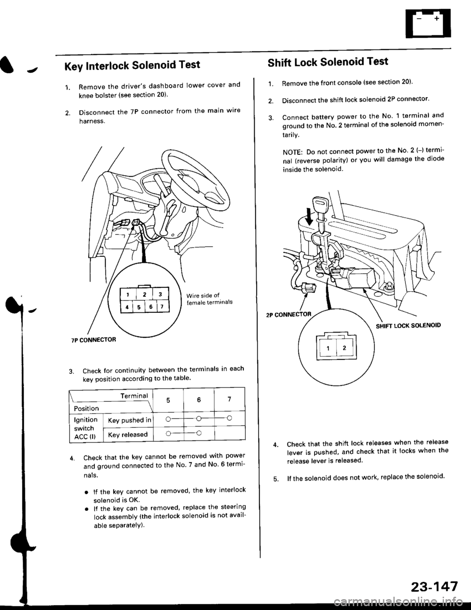
Key Interlock Solenoid Test
Remove the driver's dashboard lower cover and
knee bolster (see section 20)
Disconnect the 7P connector from the main w're
harness.
3. Check Ior continuity between the terminals in each
kev oosition according to the table'
4. Check that the key cannot be removed with power
and ground connected to the No. 7 and No 6 termi-
nals
. lf the key cannot be removed. the key interlock
solenoid is OK.
. lf the key can be removed, replace the steering
lock assembly (the interlock solenoid is not avail-
able seParatelY).
1.
Terminal
i*i,r"
- - --\7
lgnition
switch
ACC fl)
Key pushed ino--o
Key releasedo--o
Shift Lock Solenoid Test
't.Remove ths front console (see section 20)'
Disconnect the shift lock solenoid 2P connector'
Connect battery power to the No. 1 terminal and
ground to the No. 2 terminal of the solenoid momen-
Iarrry.
NOTE: Do not connect power to the No 2(-) termi-
nal (reverse polarity) or you will damage the diode
inside the solenoid
Check that the shift lock releases when the release
lever is pushed, and check that it locks when the
release lever is released
lf the solenoid does not work, replace the solenoid'
23-147
Page 1721 of 2189

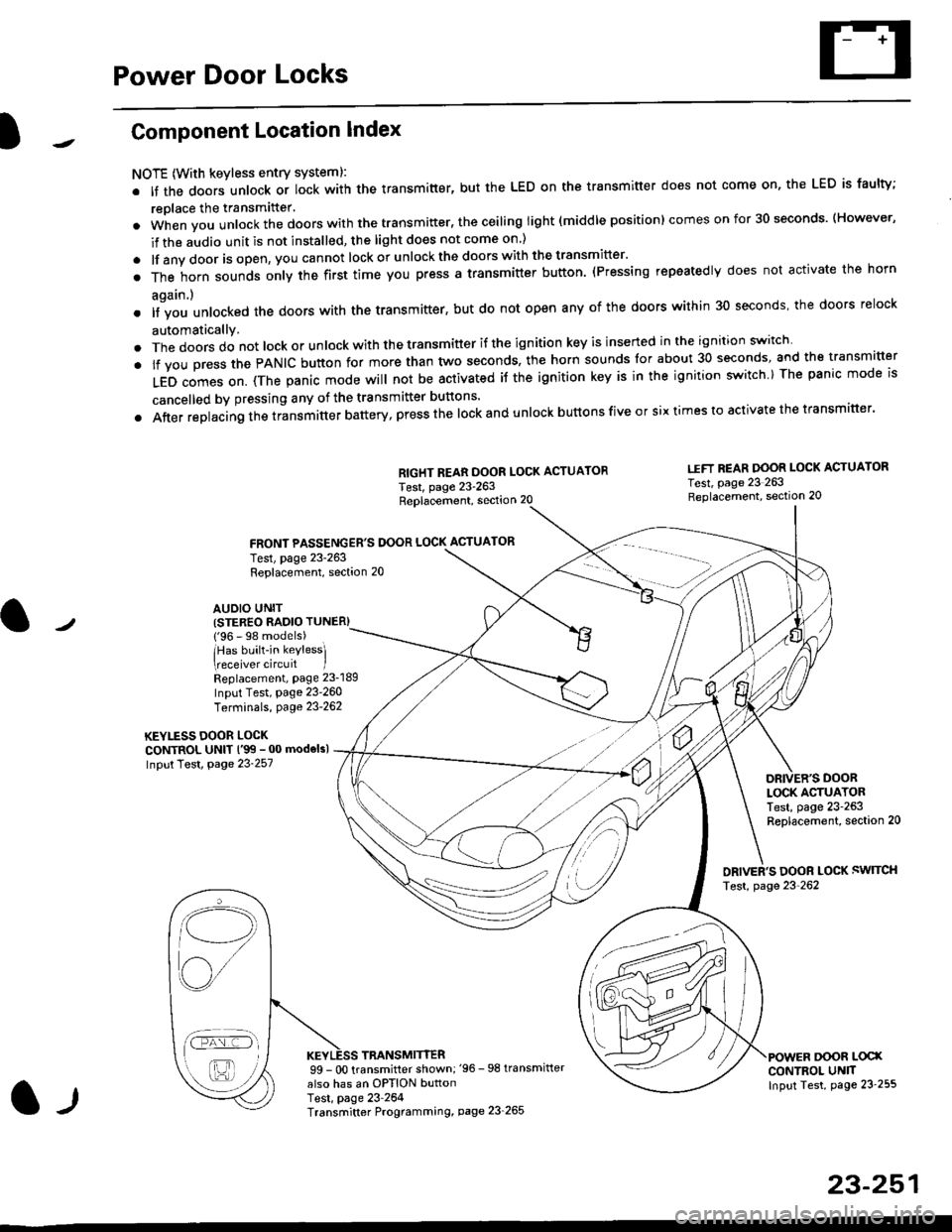
Power Door Locks
Component Location Index
NOTE (With keyless entry systeml:
. It the doors unlock or lock with the transmitter, but the LED on the transmitter does not come on, the LED is faulty;
replace the transmitter'
. when vou unlock the doors with the transmitter, the ceiling light (middle position) comes on for 30 seconds. (However,
if the audio unit is not installed, the light does not come on )
. lf any door is open, you cannot lock or unlockthe doors with the transmitter'
. The horn sounds only the first time you press a transmitter button. (Pressing repeatedly does not activate the horn
again.)
o lf vou unlocked the doors with the transmitter, but do not open any of the doors within 30 seconds, the doors relock
automatically.
. The doors do not lock or unlock with the transmitter if the ignition key is inserted in the ignition switch
. lf you press the PANIC button for more than two seconds, the horn sounds for about 30 seconds, and the transm'fer
LED comes on. (The panic mode will not be activated iJ the ignition key is in the ignition switch ) The panic mode is
cancelled by pressing any of the transmitter buttons'
o After replacing the transmitter battery, press the lock and unlock buttons five or six times to activate the transmitter'
Replacement, section 20
FRONT PASSENGER'S DOOR LOCK ACTUATOR
RIGHT REAR DOOR LOCK ACTUATOR
Test, page 23-263
I.IFT REAR DOOR LOCK ACTUATOR
Test, page 23 263Replacement, section 20
LOCK ACTUATORTest, page 23-263Replacement, section 20
ORIVER'S DOOR LOCK SWITCH
Test, page 23'262
DOOR L@XCONTROL UN]TInput Test, page 23 255
23-251
Test, page 23-263Replacement, section 20
AUDIO UNIT(STER€O RADIO TUNER)
{'96 - 98 models)
lHas built-in keylessl
eceiver circuit IReplacement, page 23-189
Input Test, page 23-260
Terminals, page 23-262
KEYLESS DOOR LOCKCONTROL UNIT l'99 - 00 modelsl
Input Test, Page 23-257
l-l
TRANSMITTER99 - 0O transmitter shown;'96 -98 transmifter
also has an OPTION buttonTest, page 23-264Transmitter Programming, page 23_265
Qi,,a/
/----
L(ru
i'.-8,-'l
/'-'6
Page 1722 of 2189

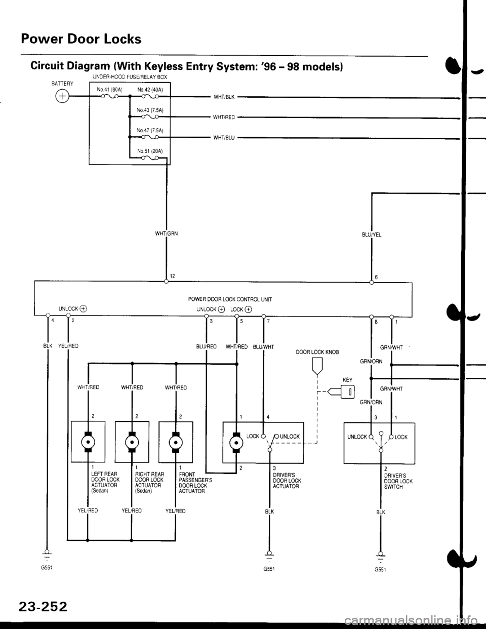
Power Door Locks
Circuit Diagram (With Keyless Entry System: '96 - 98 modelsl
WHTi BLK
WHT/BED
WHT/BLU
LOCK KNOB
n
Y KEY| -----.f--;-)
i-q__!J
8LK
G551
ll,o"., L
I PASSENGER'SI DoOF LOCKI ACTUATOR
IIYEUREO
WHT/RED WHT/FED
l,l,
tA-r rA] r.
qJ_*:[:,,,:
liqi*"""r llqi*'€trYELIRED YELi REDBLK
I
No.4l 180A) N0.42 (40A)
WHT/GRN
UNDER.HOOD FUSEi RELAY BOX
POWER OOOR LOCK CONTROL UN T
uNLocK@ rocK @
t'8LU/REDI'YELTRED
GRNiORN
GRN/]/VHT
BLK
G55l
23-252
Page 1724 of 2189

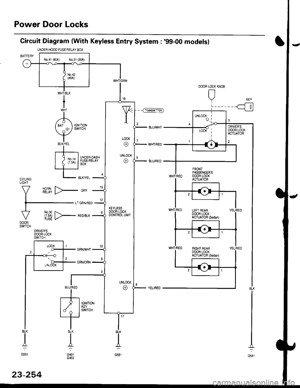
Power Door Locks
Circuit Diagram (With Keyless Entry System : '99-00 models)
BL(
I
G551
UNDEF.HOOO FUSE/RELAY BOX
N0.41 1804) N0.51 (20 )
KEYLESSDOOF LOCKCOIJTROL UNIT
DRIVEF'SDOOF LOCKSWITCH
23-254