Page 1175 of 2189

Master Cylinder/Brake Booster
IRemovaUlnstallation
CAUTION:
. Be care{ul nol to bend or damage the brake lines when
rsmoving the mastsr cYlinder.
. Do not soill brakefluid on the vehicle; it may damage
the paint; if brake fluid does contact the paint, wssh
it off immediatelY with water'
. To prevent spill3, cover the hose ioints with rags or
shop towels.
9. Remove the four booster mountlng nuts
10. Pull the brake booster forward until the clevis is
clear of the bulkhead.
11. Remove the brake booster from the engine com-
panmenr.'12. Install the brake booster and master cylinder in the
reverse order of removal.
CAUTION:
. When connecting the brake lines. make sure
that there is no inte erence between the brake
lines and oth6r Parts.
r Be careful not to bend or damage the brake lines
when installing the master cylinder.
NOTE: lf replacing the master cylinder or brake
booster, check and adiust the pushrod clearance
be{ore installing the master cylinder (see page 19-221'
Fill the master cylinder reservoir, and bleed the
brake svstem (see Page 19-7).
After installation. check the brake pedal height and
brake pedal tree play (see page l9-5) and adjust if
necessary.
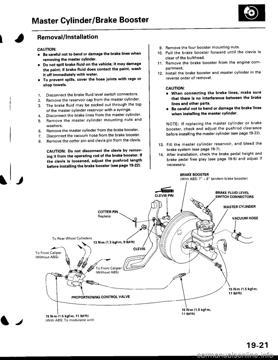
BRAKE BOOSTER(With ABS: 7" + 8" tandem brake booster)
BRAKE FLUIO LEVELSWITCH CONNECTORS
MASTER CYLINDER
VACUUM HOSE
1.
2.
3,
5.
Disconnect the brake fluid level switch connectors'
Remove the reservoir cap from the master cylinder'
The brake fluid may be sucked out through the top
of the master cylinder reservoir with a syrlnge.
Disconnect the brake lines from the master cylinder'
Remove the master cylinder mounting nuts and
washers.
\l/
6. Remove the master cylinder from the brake booster'
7. Disconnect the vacuum hose trom the brake booster'
8. Remove the cotter pin and clevis pin from the clevis'
CAUTION: Do not disconnect the clevb by remov-
ing it from the operating rod of the brako booster' lf
the clevis is loosened, adiust the pushrod length
before installing th€ brake booster (see page 19-221'
COTTER PINReplace.
To Rear Wheel Cylinders
14.
-6.4CLEVIS PIN
To Front Caliper(Without ABS)$
t'N't'ttrnt'-''
To Front CaliperlWithout ABSi
PBOPORTIONING CONTROL VALVE
15 N.m {1.5 kgl m,11 tbtft)
15 N.m {1.5 kgif.m, 11 lbtft}(With ABS: To modulator unit)lr
19-21
Page 1299 of 2189
Glove box removal:
Remove the bolts, then remove the glove box.
>: Bolt locations,2
Installation is the reverse of the removal proceoure
Side air vent/Side defogger trim removal:
SIOE DEFOGGER TRIMSHOPTOWET_Carefully PrY rt at the
then remove it,side edge,
SIDE AIR VENTRemove the driver's dashboard lower
cover, or oPen the glove Dox,
HOOKS
then push the cliPs from each
opening by hand, and Pull it
out. Disconnect the connedors(driver's side).
HOOKS
DASH LIGHTSBRIGHTNESSCONTROLLERCONNECTOR{for some models)
CFUISE CONTROLMASTER SWITCHCONNECTOR(for some models)
Center dashboard lower covel:
1. Remove:
. Driver's dashboard lower cover
. Glove box
2. Remove the screws and bolt, then remove the cen-
ter dashboard lower cover. Disconnect the accesso-
ry socket connector'
>i Boh, screw locations
a>, 1 B>'5
A s*o.e-- I A
@;*;ry'-1'-.J _e)
3. Installation is the reverse of the removal proceoure'
(cont'd)
20-69
LOWER COVER
Page 1519 of 2189
ID
*1:With power windows*2: Without Power wlndows"3: Without keyless
Driver's Door Wire Harness {Coupe/Hatchback}
Connector ot
Terminal
Numbei of
CavitiesLocationConnects toNotes
c631
UOJ I
c632
c633
c634
c635
c636
c638
c639
c640
2
2
4
4
2
12
3
8
12
Driver's door
Driver's door
Driver's door
Driver's door
Driver's door
Driver's door
Driver's door
Driver's door
Inside of left power mirror
Driver's door
Floor wire harness (C556)
Floor wire harness (C556)
Left front door speaker
Driver's power window motor
Driver's door lock actuator
Tweeter
Power window master swltch
Driver's door lock switch
Left power mirror
Power door lock control unlt
Coupe
Coupe
Coupe
Coupe
Coupe
Coupe
Coupe*3
c639
DRIVER'S DOOR WIRE HARNESS
23-49
Page 1521 of 2189
'
Driver's Door Wire Harness (Sedan)
Connector or
Terminal
Number ol LocationCavitiesConnects toNotes
c63 r
c632
c633
c634
c636
c637
c638
c639
c640
25 Driver's door
2 Driver's door
2 I Driver's door
4 Driver's door
4 Driver's door
16 Driver's door
1 Driver's door
3 Driver's door
8 Inside of left Power mirror
12 I Driver's door
Floor wire harness (C556)
Floor wire harness 1C556)
Left front door sPeaker
Driver's power window motor
Driver's door lock actuator
Power window master switch
Power window master switch
Driver's door lock switch
Left power mirror
Power door lock control unlt
*1: With power wlndows*2: Without power wlndows
DRIVER'S DOORWIRE HARNESS
Page 1690 of 2189
Power Windows
Gomponent Location Index
UNDER-DASHFUSE/RELAY BOX
POWER WINDOW RELAYTest, paqe 23 87
FRONT PASSENGER'S WINDOW SWITCHTest. page 23-230
FRONT PASSENGER'S WINDOW MOTORTest, page 23-232
POWER WINDOWMASTER SWITCH(Has built in control unit)Input Test, page 23-226f e$, page 23 224
RIGHT REAR WINOOW SWITCH {SedanlTest, page 23-230
BIGHT REAR WINDOW MOTORlSedanlTest, page 23-232
DRIVER'S WINOOW MOTORTest, page 23-231
LEFT REAR WINDOW SWITCH (Sedan)
Test, page 23-230
LEFT BEAR WINDOW MOTOR {Sedanlf e$, page 23-232
O -rr----r---- _ fl]l O-.---,---;-; n-n--n-nn--r- ! l
Page 1696 of 2189
Power Windows
Master Switch Test (Coupe/Hatchbackl
1. Remove the master switch from the driver's door
panel (see page 23-2281.
Disconnect the 12P connector from the master
switch.
MAINSWITCH
Terminal side of male terminals
3. Check for continuity between the terminals in each
switch position according to the table.
Driver's Switch:
The driver's switch is combined with the control unit so
you cannot isolate the switch to test it. Instead. run the
master switch input test procedures at terminals 41. A3,
44. A8 and Al2 on page 23-226. lf the tests are normal,
the driver's switch must be faulty.
A1IA3A4A5
A1A8,/l/412
23-226
Passenger's Switch:
Terminal
P""*;l-m;\A2A5A6A7
OFFONo---o
OFFo---o
UPON
c'---o
o---o
OFFo---o
DOWNONo---o
--oo-
OFFo---o
Page 1697 of 2189

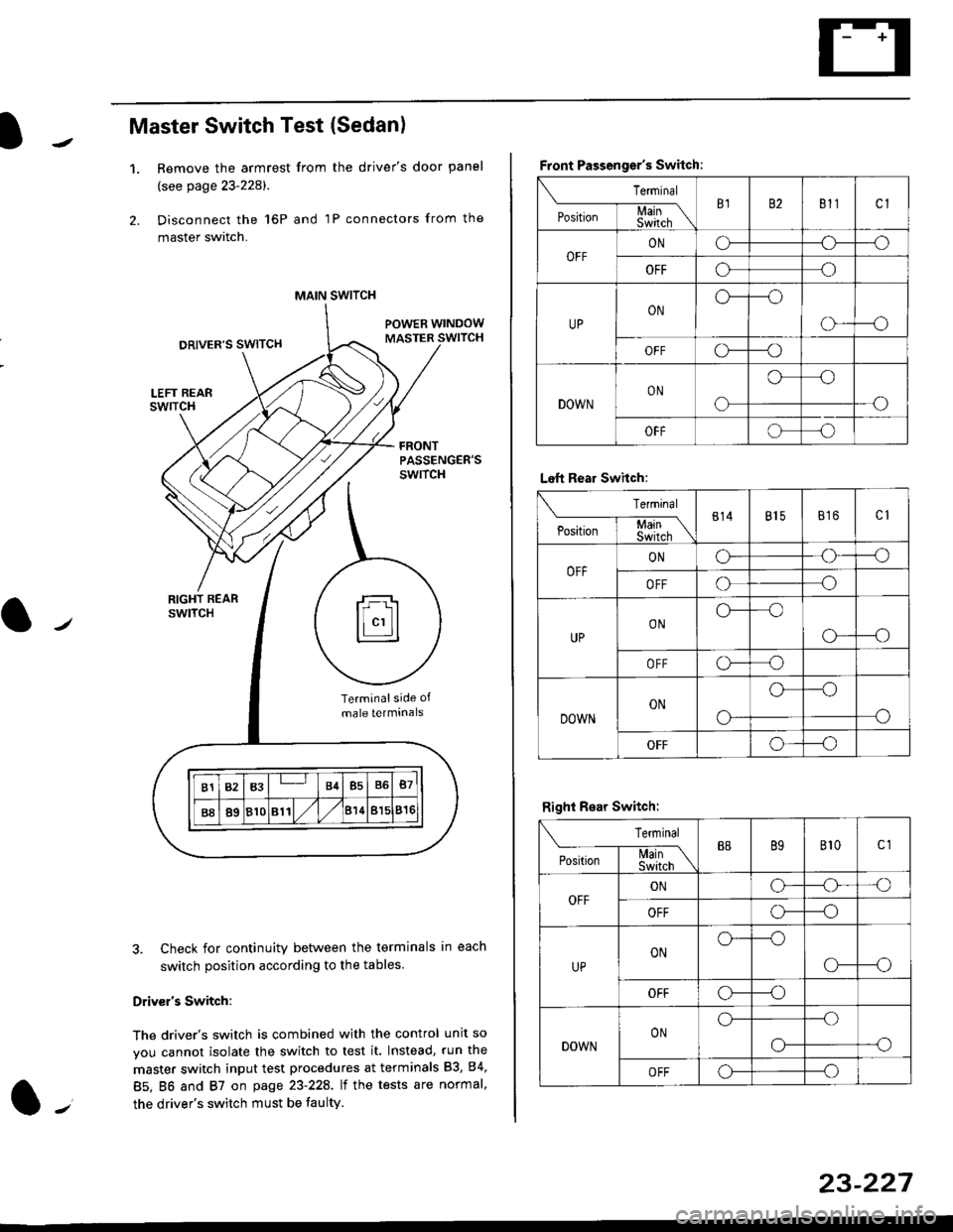
Master Switch Test (Sedan)
1.Remove the armrest from the driver's door panel
(see page 23-228).
Disconnect the 16P and 1P connectors from the
master switch.
Check for continuity between the terminals in each
switch position according to the tables
Driv€r's Switch:
The driver's switch is combined with the control unit so
you cannot isolate the switch to test it. Instead, run the
master switch input test procedures at terminals 83, 84,
85. BO and 87 on page 23-22A. lt the tests are normal,
the driver's switch must be faulty.
MAIN SWITCH
rFl
ll"'llt.:::::::l
B1B3B4B5B6B7
B889810811/l/leuBl5816
Terminalside of
male terminals
Front Passenger's Switch:
Terminal
P*,j--f$t,l"\B182811cl
OFFONCF--o
OFFooo
UPONo---o
o---o
OFFc\---o
DOWNON
o
oo
-o
OFFoo
Left Rear Swhch:
Terminal
P".r,-'-f-mn\814815816c1
OFFONG--o
OFFoo
UPONo--oo
o---o
OFFo-o
DOWNON
o-
o--o
o
OFFo--_o
Right Rear Switch:
Terminal
'**-T-*mB889B'�t0c1
OFFONo-o'o
OFFo---o
UPONo---o
CF--o
OFFCr---o
DOWNONo---.o
--oo-
OFFo---o
23-227
Page 1698 of 2189
Power Windows
Master Switch Input Test {Coupe/Hatchback)
NOTE: The control unit is built into the power window master switch, and only controls driver's door window operatlons.
l� Remove the driver's door panel, and disconnect the 12P connector from the master switch.
2. Inspect the connector and socket terminals to be sure they are all making good contact.
. lf the terminals are bent, loose or corroded, repairthem as necessary, and recheck the system.
. lf the terminals look OK, make the following input tests at the connector.- lf a test indicates a problem, find and correct the cause. then recheck the system.- lf all the input tests prove OK, the power window master switch must be faulty; replace it.
23-228
Ware side of female terminals