1999 HONDA CIVIC vacuum line
[x] Cancel search: vacuum linePage 502 of 2189

\J
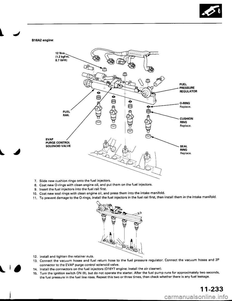
81642 engine:
EVAP
12 N.m
{1.2 kgl m;8.? lbt.ft)
FUELPRESSUREREGULATOR
O.RINGReplace.
cusHloNRINGReplace.
PURGE CONTROLSOLENOID VALVE
\
SEALRINGReplace.
7. Slide new cushion rings onto the fuel injectors.
8. Coat newO-ringswith clean engineoil, and putthem onthefuel injectors.
9. Insert the fuel injectors into the fuel rail first.
10. Coatnewseal rings with clean engine oil,and press them intothe intake manifold.
11. To prevent damage to the O-rings, installthe fuel injectors inthefuel rail first, then install them inthe intake manifold.
'12. Install and tighten the retainer nuts.
13. Connect the vacuum hoses and fuel return hose to the fuel pressure regulator, Connect the vacuum hoses and 2P
connector to the EVAP purge control solenoid valve.
14. Install the connectors on the fuel inl'ectors (D16YI engine; Install the air cleaner).
15. Turn the ignition switch ON (ll), butdo not operate the starter. After the tuel pump runs for approximately two seconds,
the fuel pressure in the fuel line rises. Repeat this two or three times, then check whether there is any fuel leakage.
11-233
Page 520 of 2189

\J
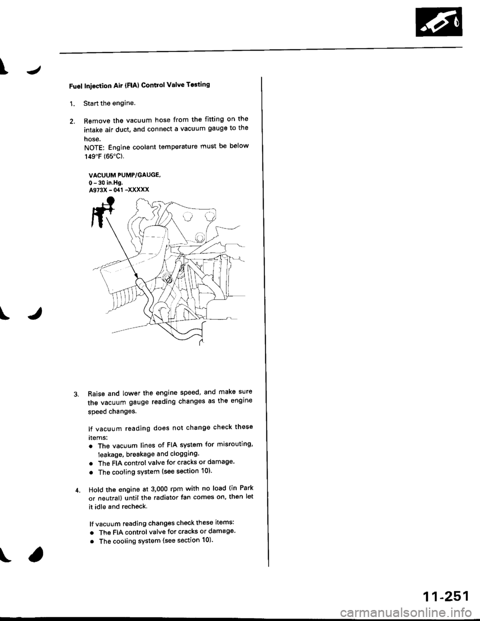
Fuol Iniection Air {FlA) Contlol Valve T$ting
1. Start the engine.
2. Remove the vacuum hose from the fitting on the
intake air duct, and connect a vacuum gauge to the
nose.
NOTE: Engine coolant temperature must be below
149"F (65"C).
VACUUM PUMP/GAUGE,
0-30 in.Hg.A973X - 041 -XXXXX
Raise and lower the engine speed, and make sure
the vacuum gauge reading changes as the engine
speed changes.
lf vacuum reading does not change check these
rtems:
. The vacuum lines of FIA system for misrouting,
leakage, breakage and clogging.
. The FIA controt valve for cracks or damage
. The cooling system (see section 10).
Hold the engine at 3,OOO rpm with no load (in Park
or neutral) until the radiator fan comes on, th€n let
it idle and recheck.
lf vacuum reading changes check these items:
a The FIA control valve for cracks or damage.
. The cooling system (see section 10).
11-251
Page 526 of 2189
![HONDA CIVIC 1999 6.G Workshop Manual \EGR VALVELIFT SENSOR#16 HOSE
I
(From page 11-256)
EGR VALVE LIFT SENSOR3P CONNECTOR lC14.l)
zF vcczI- . ] IYEL/BLU)ll 2l3l---l-r_ 7 |
v-,, ISG2IGRN/BLK) I ^ II{Vts
ECM CONNECTOR D {16P)
PUMP/GAUGE,0 HONDA CIVIC 1999 6.G Workshop Manual \EGR VALVELIFT SENSOR#16 HOSE
I
(From page 11-256)
EGR VALVE LIFT SENSOR3P CONNECTOR lC14.l)
zF vcczI- . ] IYEL/BLU)ll 2l3l---l-r_ 7 |
v-,, ISG2IGRN/BLK) I ^ II{Vts
ECM CONNECTOR D {16P)
PUMP/GAUGE,0](/manual-img/13/6068/w960_6068-525.png)
\EGR VALVELIFT SENSOR#16 HOSE
I
(From page 11-256)
EGR VALVE LIFT SENSOR3P CONNECTOR lC14.l)
zF vcczI- . ] IYEL/BLU)ll 2l3l---l-r_ 7 |
v-,, ISG2IGRN/BLK) I ^ II{Vts
ECM CONNECTOR D {16P)
PUMP/GAUGE,0 - 30 in.Hs4973X-041-XXXXX
sG2(GRN/BLKIvcc2IYEL/BLU}
Wire side ol temale terminals
PCM CONNECTORS C (31P}'
YES
Wire side of female terminals
1
(cont'd)
1-257
Check fo. a mallunction in theEGF valv€:1. ldove the vacuum pump/gauge
to the EGR valve.2. With the engine at idle, apply
26.7 kPa (200 mmHg,8.0 in.Hg)
ofvacuum to the EGR valve.
Does the engine stall or runrough and does the EGR valvehold vacuum?
Check for an open in the wire
IVCC2linel:1. Turn the ignition switch OFF.2. Disconnect the EGR valve liftsensor 3P connector.3. Turn the ignition switch ON (ll).
4. Measure voltage between theEGR valve lift sensor 3P con'
nector terminals No. 3 and
No.2.
ls lhere approx.5 V?
Check for an oDen in the wire
{VCC2 line}:Measure voltage between theECM/PCM connector terminalsD10 and Dl1 (C18 and C28)*.
Rep.ir open in the wire betweenrhe EGR valve snd ECM/PCM
{Dl0 {C28)*).lsthere approx.5 V?
Sub3titute t known-good ECM/PCM end recheck. lt 3ymptom/indication goos eway, replaceth6 original ECM/PCM.(To page 1l-258)*: '99 - 00 models
Page 528 of 2189

I
I
Wire side of lemale terminals
PCM CONNECTORS C (31P)*
ECM CONNECTOR O {I5PI
Wire side of temale terminals
t
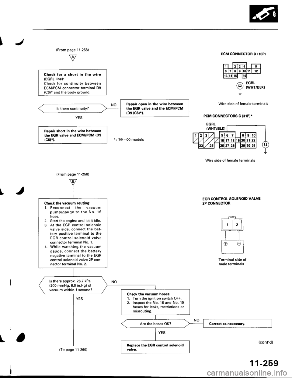
(From page 11-258)
Check for a 3hort in the wire
{EGRL linel:Check for continuity betweenECM/PCM connector terminal Dg
Repair op€n in the wire betweenth6 EGR valve and the ECM/PCM(D9 tc6trt.
ReDair short in the wirc batweonthe EGR valve and ECM/PCM {Og(c5t*).
(From page 11-258)
11,260)
Check ths vacuum routing:'1. Recon nect the vacuumpump/gauge to the No. 16hose.2. Start the engine and let it idle.3. At the EGR control solenoidvalve side, connect the bat-tery positive terminal to theEGR control solenoid valveconnectot terminal No. 1.4. While watching the vacuumgauge, connect the batterynegative terminal to the EGRcontrol solenoid valve 2P con-nector terminal No. 2,
ls there approx.26.7 kPa
1200 mmHg,8.0 in.Hg) ofvacuum within 'l second?Chock the vlcuum hos6s:1. Turn the ignition switch OFF.2. Inspect the No. 16 and No. 10hoses for leaks, restrictions ormtsrouUng.
EGR CONTROL SOLENOID VALVE
2P CONNECTOR
Terminal side oImale lerminals
(cont'd)
11-259
Page 540 of 2189

\J
\
,96 D16Y5 engine,,96 D16r,gngino,,96 Dt6Y8 engine {3edan)' 37 D16Y5 engino..97 D16r, engine {coupe: KA, Kc mod-
els. sedan: KA, KC, KL {DX} models. hatchback: all modols}''97 Dl6Y8 ongine (s€dan: KA' KC mod€lsl:
The scan tool indicates Diagnostic Trouble code (DTC) P0441: Evaporative Emission (EVAP) control system
insufficient purge flow.
Description
By monitoring the purge line vacuum with the MAP sensor, the ECM/PCM can detect insufficient EVAP control system
purge flow.
Possible Cau3e
. EVAP Purge Control Solenoid Valve
. EVAP Purge Control Solenoid Valve Circuit
. EVAP Control Canister
. Vacuum Lines
. ECM/PCM
Troubl93hooting Flowchart
Wire side of femaleterminals
EVAP PURGE CONTROI-sottNotD vALvE 2P
CoNNECTOR (Cl1al
r-+-r
I'l'l
lG-ro.*l'rr"r
O)
Y
(cont'd)
11-271
- The MIL has bsGn.eportad on.- DTC milal k rtored.
Pioblem vsrificJtion:1. Start the engine. Hold the
engine at 3,000 rPm with no
load {in Park or noutral) until
the radiator fan comes on.
2. Do the ECM/PCM Reset Proce'
dure,3. Connect the SCS service con-
nector.4. Test-drive under following con-
ditions on the road- Without any electrical load- A/T in E or E Position(M/T in 3rd-sth gear)- Engine sPeed betweon
1,200 - 2.400 rpm.- Decelerate {rom 50 mph (80
knl/h)to 15 mph (24 km/h)lntormittont lailuro, sFtorn b OK
at thi. timo. Ch€ck tor Poor con'
ncction3 or looac wir.3 at C144
{EVAP purgo control tolonoid
vrtv.l .nd ECir/FCttl.
ls DTC P0441 indicatod?
Ch.ck fo. !n op€n in the wiro l|(illinel:1. Turn the ignition switch OFF.
2. Disconnect the EVAP Purgecontrol solenoid valve 2P con_
neclor,3. Turn the ignition switch ON (ll)
4. Measur€ voltage between bodyground and the EVAP Purgecontrol solenoid valve 2P con-
nector terminal No 1.
Rop.ir opor in tho wir6 b€two€n
the EVAP purgo codtiol tolonoid
v.lvo rnd tho No 15 ALIERNA'
TOR SP SENSOR 17.5 A)lu.o.
{To page 11-272)
Page 541 of 2189

Emission Gontrol System
Evaporative Emission (EVAPI Controls (cont'dl
(From page 11-271)
I
ECM/PCM CONNECTOR D I32P}
PGl IBLKI
Check the EVAP purge controlsolenoid valvei1. Reconnect the EVAP purge
control solenoid valve 2P con-nector.2. Connect ECM/PCM connectorterminals A15 and 410 with a
Check for an open or short in thewire (PCS line):Measure voltage between ECM/PCM connector terminal A15 andbody gro!nd.
Does the solenoid valve clickwhen the jumper is connected?
Che'ck for a short in the wir6 {PCSline):1. Turn the ignition switch OFF.2. Disconnect the ECM/PCM con-nector A (32P).
3. Disconnect the EVAP purgecontrol solenoid valve 2P connector.4. Check lor continuity betweenbody ground and ECM/PCMconnector terminal A15.
Repai. short in the wir6s betwoonthe EVAP purge control solanoidvalve and ECM/rcM lA15l.
R€pair op€n in the wir$ betwo€ntho EVAP purge control solenoidvalve and ECM/rcM lA15l.
Check the vacuum lin€3:Check the vacuum lines ol EVAPsystem for misrouting, leakage,breakage and clogging.
Are the vacuum lines OK?
PCS {REO/YEL)
t389t0'tt
12l3'I'tt5t5'11IE1920232a
?5212A2930
PCS {RED/YEL)
23a67E9t0It
12t3'ta't5l617ta1920222321
2a2728A30
0) Pcs {REo/YELI
-272
Page 544 of 2189

\J
Fuel Tank Pro3sure sensor 196 D16Y8 engine (coupe).'97 D15Y7 engine {coupe: KL model, sedan: KL (LX) modeu,'97
D16Y8 engine (coupe: all models, sedan: KL model, '98-all models) '99 - 00 D16Y5 engine with M/Tl:
\
PTANK
{LT GRNI
vcc2(YEL/BLU}
Wire side oI female terminals
FUEL TANKPRESSURE SENSOR3P CONNECTOR (C7921
sG2IGRN/8LK)
Foc2l::il":"toolindicatesDiagnosticTroublecode(DTc)P0452:A|owvo|tageprob|emintheFue|TankPressure
The fuel tank pressure sensor converts fuel tank absolute pressure into electrical signals and inputs the EcM/PCM.
OUTPUTVOLTAGEtvt4.5
-? kPa(-50 mmHg,-2 in.Hg)
ECM/PCM CONNECTOR O I16P)
Wire side of female terminals
+7 kPs150 mmHg,2 in.Hg)
PRESSURE
(cont'd)
11-275
- The MIL has been reported on- DTC P0452 is stored.
Check the vacuum lines:
Check the vacuum lines of the
fuel tank pressure sensor for mis-
routing, leakage, breakage and
cloggrng.
Are the vacuum lines OK?
Problem v€ritication:1. Do the ECM/PCM Reset Proce
dure.2. Remove the luel fill caP.
3. Turn the ignition switch ON lll)4. Monitor the FTP Sensor volt_
age with the Honda PGM
Tester, or measure voltage
between bodY ground and
ECM/PCM terminal Dl5.lntermittent tailuro, sYstem i5 OK
dt this timo. Chock for Poot con-
neciion3 or loose wir* at C131
llocatod under right side ot dashl,
C4O1 (located .bove under'da3htuso/ielay box), C574 1C568)*
{located under acc€ss Panell.C792 lfuel tank pressule sen3or)
and EcM/PCM.
ls there approx. 2.5 V?
Check tol an op€n in wite (VCC2
line):1. Turn the ignition switch OFF
2. Reinstallthe fuel fill caP.3. Disconnect the fuel tank Pres'sure sensor 3P connector-4. Turn the ignition switch ON (ll)
5, Measure voltage between the
fuel tank pressure sensor 3P
connector No. l terminal and
No. 2 terminal.
Repair open in the wite betweenthe fuel tank Pr€s3ure a€n3or andth6 EcM/PcM (D1ol.ls there approx. 5 V?
(To page 11'276)
Page 546 of 2189

\
'99 - 00 models excepi Dl6Y5 engine with M/T:
The scan tool indicates Diagnostic Trouble Code (DTC) P0452: A low voltage problem in the Fuel Tank Pressure
sensor.
The fuel tank pressure sensor converts fuel tank absolute pressure into electrical signals and inputs the ECM/PCM
OUTPUTVOLTAGE(vlt.5
0.5-7 kP.(-g) mmHg,-2 in.Hgl
+7 kP.
150 mmHg,2 in.Hgl
PRESSURE
I
Wire side of lemale terminals
FUEL TANKPRESSURE SENSORSUB.HARNESS6P CONNECTOR (C574 (C568)rl
vcc2(YEL/BLUIsG2{GRN/BLK}
Wire side o{ temale terminals
The MIL has been .eported on.
DTC P0452 is stored
Check the vacuum lines:
Check the vacuum lines of the
fuel tank pressure sensor lor mis-
routing, leakage, breakage and
cloggrng.
Are the vacuum hnes OK?
Problem veritication:1. Do the ECM/PCM Reset Proce-
du re,2. Bemove the fuel fill caP.
3. Turn the ignition switch ON {ll)
4. Monitorthe FTP Sensor voltage
with the Honda PGM Tester' or
measure voltage between body
groLrnd and ECM/PCM connec_
tor terminalA29.
lntermitlent tailure, 3Ystem b OK
at this time. Check for Poor con'
nections or loose wire3 at C131
{located under right side of dash},
C401 {located above under'dash
tuse/relay box), C574 (C568)*
llocdted under access Panel),C792 (tuel rank Prcssure sensorl
and ECM/PCM.
ls there approx.2 5 V?
Check for an open in wire {VCC2
line):1. Turn the ignition switch OFF.
2. Reinstall the ltrel fill caP
3, Remove the access Panel from
the floor.4. Disconnect the fuel tank Pres'sure sensor sub-harness 6P
5. Turn the ignition switch ON (ll).
6. At the access Panel side, mea_
sure voltage between the fuel
tank Pressure sensor sub-nar-
ness 6P connector No 5termi
nal and No. 6 termlnal.
Repair open in tho wire between
th6 fu€l tank Prossuro sen3oa and
the ECM/PCM lc28).ls there approx 5 V?
ECM/PCM CONNECTOR A (32P)
PTANK {LT BLUI
I
ll
(To page '11-278)
(cont'd)