1999 HONDA CIVIC key
[x] Cancel search: keyPage 2036 of 2189
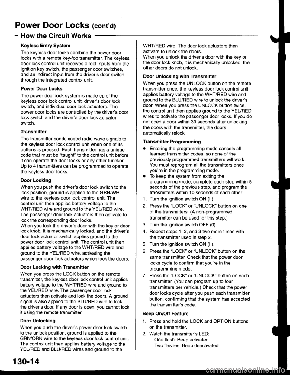
Power Door Locks (conrd)
- How the Circuit Works
Keyless Entry System
The keyless door locks combine the power door
locks with a remote key-fob transmitter. The keyless
door lock control unit receives direct inputs from the
ignition key switch, the passenger door switches,
and an indirect inDut from the driver's door switch
through the integrated control unit.
Power Door Locks
The power door lock system rs made up ot the
keyless door lock control unit, driver's door lock
switch, and individual door lock actuators. The
power door locks are controlled by the driver's door
lock switch and the driver's door lock actuator
switch.
Transmittel
The transmitter sends coded radio wave signals to
the keyless door lock conlrol unit when one of its
buttons is pressed. Each transmitter has a unique
code that must be 'laught" to the conlrol unit before
it can operate the door locks or any other function.
Up to 4 transmitters can be programmed to operate
the keyless door locks.
Door Locking
When you push the driveas door lock switch to the
lock position, ground is applied to the GRNMHT
wire to the keyless door lock control unit. The
control unit then applies battery voltage to the
WHT/RED wire and ground to the YEURED wire.
The passenger door lock actuators then activate to
lock the corresponding door locks.
When you lock the dnver's door with the key or door
lock knob, it is mechanically locked, and the driver's
door lock actuator switch applies ground to the
oower door lock control unit. The control unit then
applies battery voltage to the WHT/RED wire and
ground to the YEURED wire, activating the
passenger door lock actuators which lock the doors.
Door Locking with Transmitter
When you press the LOCK button on the remote
transmitter, the keyless door lock control unil applies
battery voltage to the WHT/RED wire and ground to
the YEURED wire. The passenger door lock
actuators then activate and lock the doors. A ground
signal is also applied to the BLU/RED wire to lock
the driver's door. lf any door is open, you cannot lock
it using the remote transmitter.
Door Unlocking
When you push the driver's power door lock switch
to the unlock position, ground is applied to the
GRN/ORN wire to the keyless door lock control unil.
The control unit then applies battery voltage to the
YEUREO and BLU/RED wires and oround to the
WHT/RED wire. The door lock actuators then
activate to unlock the doors.
When you unlock the driver's door with the key or
the door lock knob, it is mechanically unlocked; the
other doors do not unlock.
Door Unlocking with Transmitter
When you press the UNLOCK button on the remote
transmitter once, the keyless door lock control unit
applies battery voltage to the WHT/RED wire and
ground to the BLU/RED wire to unlock the driver's
door. When you press the UNLOCK button twice,
the control unit then applies ground to the YEURED
wires lo activate the passenger door locks. lf you do
not open a door within 30 seconds after unlocking
the doors with the transmitter, the doors
automatically relock.
Transmitter Programming
. Entering the programming mode cancels all
learned transmitter codes, so none of the
previously programmed transmitters will work.
You must reprogram all the transmitters once
you're in the programming mode.
. To keep the system from exiting the
programming mode, complete each step within 5
seconds of the previous step, and program the
transmitters within 10 seconds of each other.'1 . Turn the ignition switch ON (ll).
2. Press the "LOCK" or "UNLOCK" button on one
of the transmitters. (A non-programmed
transmitter can be used for this step.)
3. Turn the ignition switch OFF (0).
4. Repeat steps 1, 2, and 3 two more times with
the transmitter used in step 2.
5. Turn the ignition switch ON (ll).
6. Press the "LOCK" or "UNLOCK" button on the
same transmitter. Check that the power door
locks cycle to confirm that you're in the
programmrng mooe.
7. Press the "LOCK" or "UNLOCK" button on each
lransmitter. (You can program up to four
lransmitters per vehicle.) Check that the power
door locks cycle after you push each transmitter
button, contirming that the system has accepted
the transmitter's code.
Beep On/Off Feature
1 . Press and hold the LOCK and OPTION buttons
on the transmitter.
2. Watch the transmitter's LED:
One flash: BeeD activated.
Two flashes: Beep deactivated.
130-14
Page 2037 of 2189
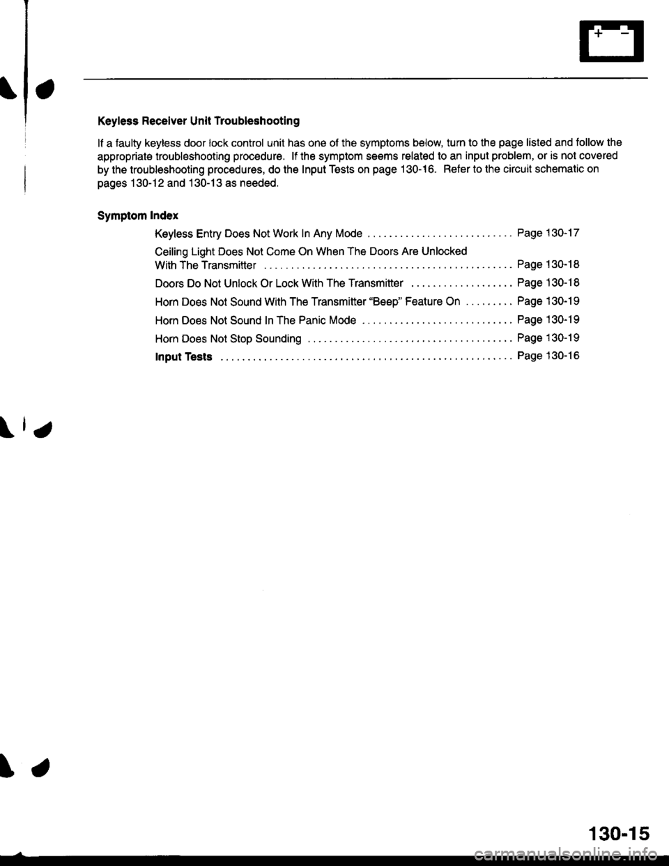
Keyless Receiver Unit Troubleshooting
lf a faulty keyless door lock control unit has one of the symptoms below, turn to the page listed and tollow the
appropriate troubleshooting procedure. lf the symptom seems relatod to an input problem, or is not covered
by the troubleshooting procedures, do the Input Tests on page 130-16. Refer to the circuit schematic on
pages 130-12 and 130-13 as needed.
Symptom Index
Keyless Entry Does Not Work In Any Mode
Ceiling Light Does Not Come On When The Doors Are Unlocked
With TheTransmitter ....
Doors Do Not Unlock Or Lock With The Transmitter . .
Horn Does Not Sound With The Transmitter 'Beep" Feature On .........
Horn Does Not Sound In The Panic Mode ..
HornDoes NotStopSounding ...............
Page 1 30-17
Page 130- 18
Page 130-1 I
Page 130-19
Page 130-19
Page 1 30-19
Page 130-16Input Tests
\.
130-15
Page 2038 of 2189
Power Door Locks (cont'd)
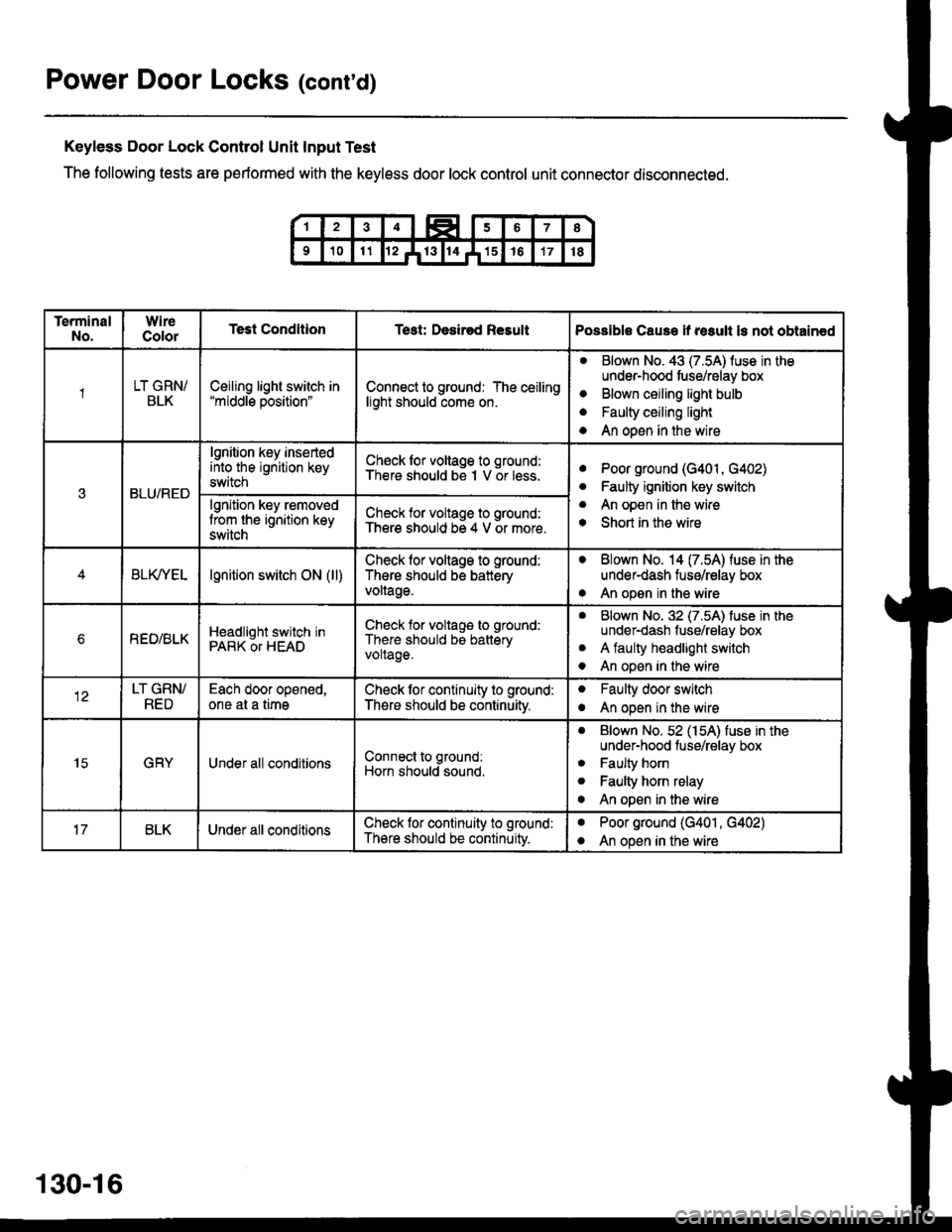
Keyless Door Lock Control Unit Input Test
The following tests are performed with the keyless door lock control unit connector disconnected.
TerminalNo.WireColorTest ConditionTest: Desir€d ResultPossible Cause if result ls not obtain€d
1LT GRN/BLKCeiling light switch in"middle position"Connect to ground: The ceilinglight should come on.
aBlown No. 43 (7.5A) luse in theunder-hood tuse/relay box
Blown ceiling light bulb
Faulty ceiling light
An open in the wire
o
a
a
3BLU/RED
lgnition key insertedinto the ignition keyswitch
Ch€ck lor voltage to ground:There should be I V or less.aPoor ground (G401, G402)
Faulty ignition key switch
An open in the wire
Short in the wire
a
a
o
lgnition key removedlrom the ignition keyswitch
Check for voltage to ground:There should be 4 V or more.
BLfiEtlgnition switch ON (ll)Check lor voltage to ground:
There should be batteryvoltage.
. Blown No. 14 (7.54) fuse in theunder-dash fuse/relay box
. An open in the wire
bREO/BLKHeadlight switch inPARK OT HEAD
Check for voltage to ground:
There should be batteryvoltage.
aBlown No. 32 (7.5A) luse in theunder-dash fuse/relay box
A faulty headlight switch
An open in the wire
a
o
LT GRN/RED
Each door opened,one at a timeCheck lor continuity to ground:
There should be continuitv.
oFaulty door switch
An open in the wireo
15GRYUnder all conditionsConnect to ground:
Horn should sound.
. Blown No. 52 (154) fuse in theunder-hood fuse/relay box
. Faulty horn
. Faulty horn relay
o An open in the wire
BLKUnder all conditionsCheck lor continuity to ground:
There should be continuity.
aPoor ground (G401 , G402)
An open in the wirea
130-16
Page 2039 of 2189
rl,
;
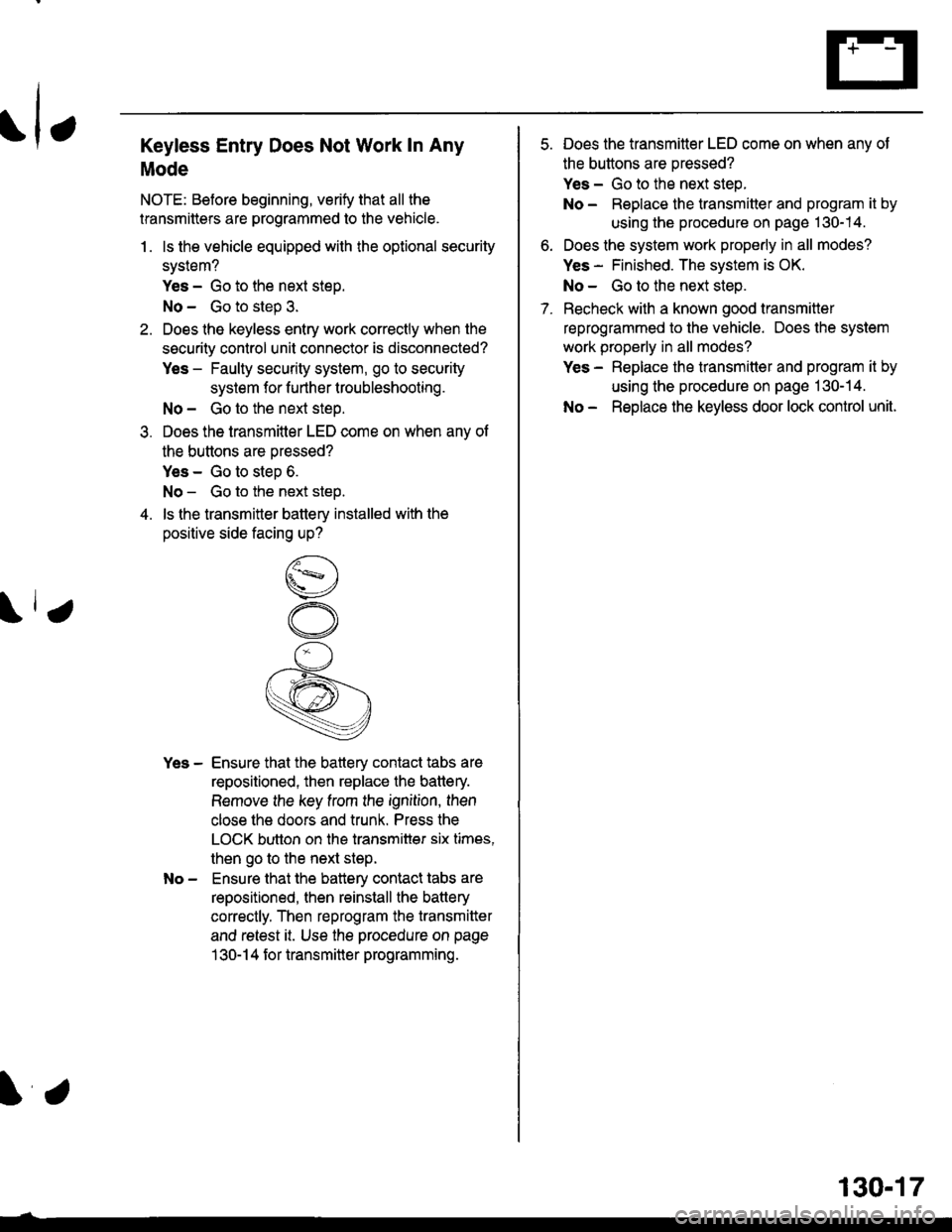
Keyless Entry Does Not Work ln Any
Mode
NOTE: Before beginning, verify that all the
transmitters are programmed to the vehicle.
1. ls the vehicle equipped with the optional security
system?
Yes - Go to the next steD.
No - Go to step 3.
2. Does lhe keyless entry work correctly when the
security control unit connector is disconnected?
Yes - Faulty security system, go to security
system for f urther lroubleshooting.
No - Go to the next steo.
3. Does the transmitter LED come on when anv of
the buttons are pressed?
Yes - Go to step 6.
No - Go to the next step.
4. ls the transmitter battery installed with the
positive side facing up?
Yes - Ensure that the battery contact tabs are
repositioned, then replace the battery.
Remove the key trom the ignition, then
close the doors and trunk. Press the
LOCK button on the transmitter six times,
then go to the next step.
No - Ensure that the battery contact tabs are
repositioned, then reinstall the battery
correctly. Then reprogram the transmitter
and retest it. Use the procedure on page
1 30-1 4 for transmitter programming.
130-17
7.
Does the transmitter LED come on when anv of
the buttons are oressed?
Yes - Go to the next steo.
No - Replace the transmitter and program it by
using the procedure on page 130-14.
Does the system work properly in all modes?
Yes - Finished. The system is OK.
No - Go to the next step.
Recheck with a known good transmitter
reprogrammed to the vehicle. Does the system
work properly in all modes?
Yes - Replace the transmitter and program it by
using the procedure on page 130-14.
No - Replace the keyless door lock control unit.
Page 2040 of 2189
Power Door Locks (cont'd)
Ceiling Light Does Not Come On When
The Doors Are Unlocked With The
Transmitter
1 . ls the ceiling light switch in the center position?
Yes - Go to the next steD.
No - Reposition the ceiling light switch and
relesI.
2. Does the ceiling light come on with the ceiling
light switch in the ON position?
Yes - Go to the next steo.
No - Repau the ceiling light circuit.
3. Does the transmitter LED come on when anv of
the buttons are oressed?
Yes - Go to the next step.
No - Check the transmitter battery, then retest.
lf the ceiling light still does not work, go to
the next step.
4. Recheck with a known good transmitter
reprogrammed to the vehicle. Does the system
work properly in all modes?
Yes - Replace the transmitter and program it by
using the procedure on page 130-14.
No - Go to the next step.
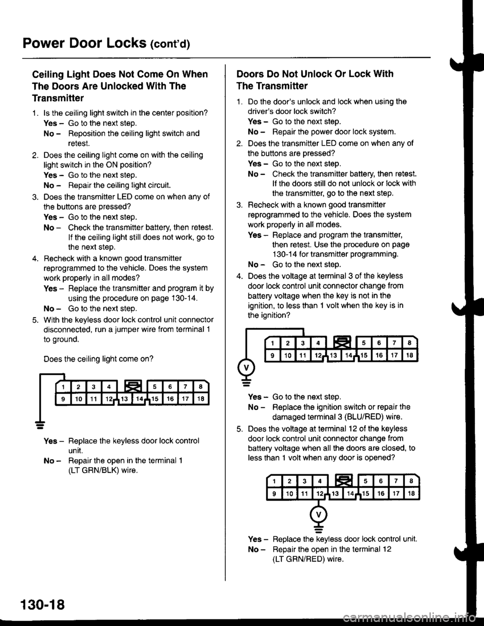
5. With the keyless door lock control unit connector
disconnected, run a jumper wire from terminal 1
to ground.
Does the ceiling light come on?
Yes - Replace the keyless door lock control
un [.
No - Repair the open in the terminal I
(LT GRN/BLK) wire.
130-18
Doors Do Not Unlock Or Lock With
The Transmitter
1 . Do the door's unlock and lock when using the
drivefs door lock switch?
Yes - Go to the next steo.
No - Repair the power door lock system.
2. Does the transmitter LED come on when anv of
the buttons are oressed?
Yes - Go to the next steo.
No - Check the transmitter batlery, then retest.
lf the doors still do not unlock or lock with
the transmitter, go to the next step.
3. Recheck with a known good transmitter
reprogrammed to the vehicle. Does the system
work properly in all modes.
Yes - Replace and program the transmitter,
then retest. Use the procedure on page
1 30-1 4 for transmitter programming.
No - Go to the next steo.
4. Does the voltage at terminal 3 of the keyless
door lock control unit connector change from
battery voltage when the key is not in the
ignition, to less than 1 volt when the key is in
the ignition?
Yes - Go to the next step.
No - Replace the ignition switch or repair the
damaged terminal 3 (BLU/RED) wire.
5. Does the voltage at terminal 12 of the keyless
door lock control unit connector change from
battery voltage when all the doors are closed, to
less than I volt when any door is opened?
Replace the keyless door lock control unit.
Reoair the ooen in the terminal 12
(LT GRN/RED) wire.
Page 2041 of 2189
Horn Does Not Sound In The Panic
Mode Or With The Transmitter "Beep"
Feature On
NOTE: The transmitter has a Beep On/Ott toature.
Refer to page 130-14 for how lo turn the be€p on or
off.
1. Does the horn sound whon the HORN button is
oressed?
Yes - Go to the next step.
No - Repair the horn circuit.
2. Does the transmitter LED come on when any of
the buttons are Dressed?
Yes - Go to the next steP.
No - Check the transmitter battery, then retest.
lf the beep feature still does not work, go
to the next steo.
3. Recheck with a known good transmitter
reprogrammed to the vehicle. Does the system
work properly in all modes?
Yes - Replace and program the transmitter,
then retest. Use the procadure on pag€
1 30-1 4 for transmitter programming.
No - Go to the neLt siep.
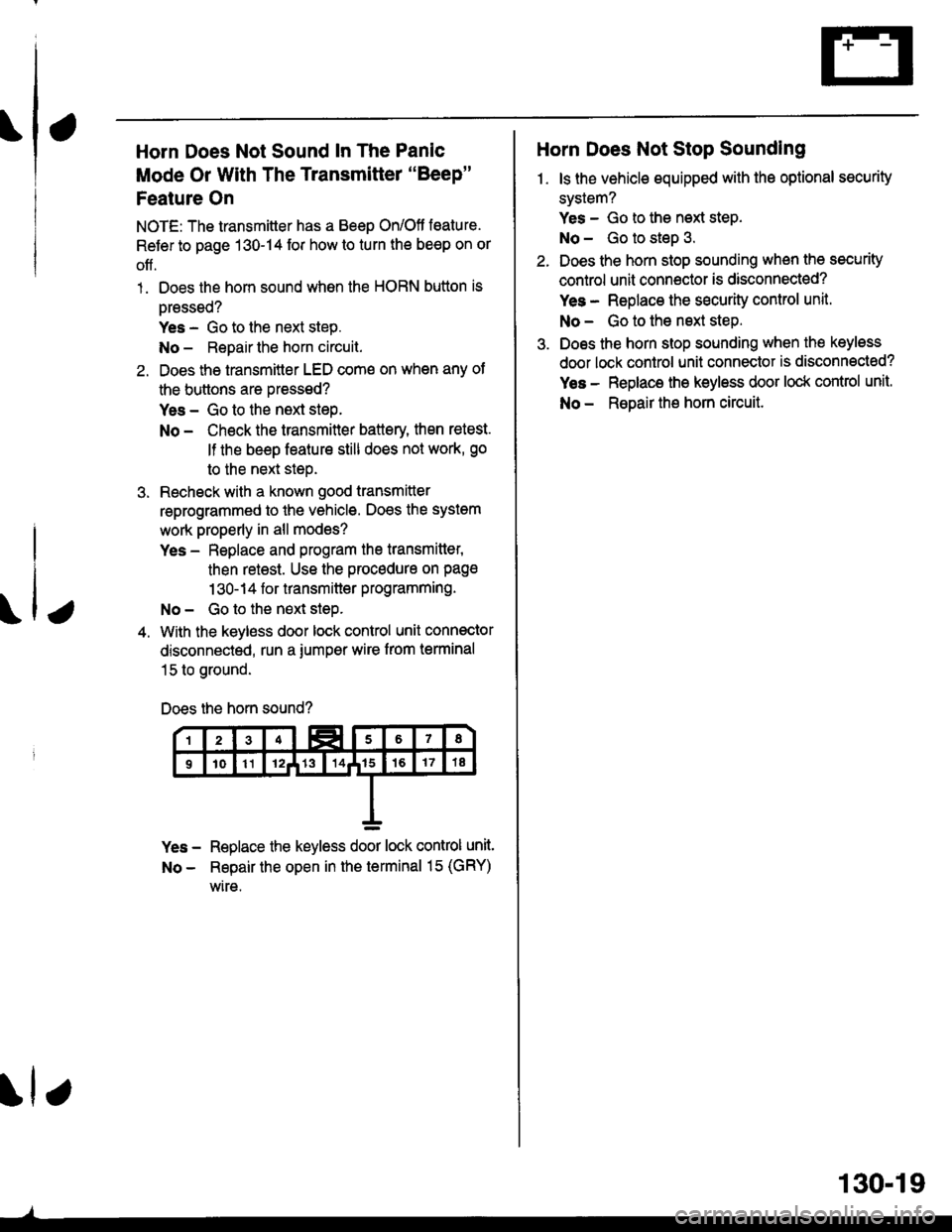
4. With the keyless door lock control unit connector
disconnected, run a iumper wire from terminal
15 to ground.
Does the horn sound?
Yes - Replace the keyless door lock control unit.
No - Repair the open in th€ terminal 15 (GRY)
wire.
\lr
130.19
Horn Does Not Stop Sounding
1. ls the vehicle equipped with the optional security
system?
Yes - Go to the next step.
No - Go to steD 3.
Does the horn stop sounding when the security
control unit connoctor is disconnected?
Yes - Replace the sEcurity control unit.
No - Go to the nsxt step.
Does the horn stop sounding when the keyless
door lock control unit connector is disconnected?
Yes - Replace the keyless door lock control unit.
No - ReDair the horn circuit.
Page 2042 of 2189
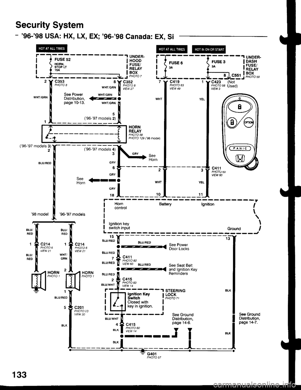
Security System
- '96-'98 USA: HX, LX, EX; '96-'98 Canada: EX. Si
UNDER-HOODFUSE/RELAYBOX
t"'1,",*
,";;;i[ftT"fi'
'lffi;?'- 1
Dfstnoulon. fuO wnr I yEL
,-l_""__
UNDER.DASHFUSE/RELAYBOX
@@
.-"*luuu' ",-f
*'^'*'
,..1
f::T;J
I I
-Tl[3,*,,,*-"""
| |
%;1 l
FUSE 3
I I C5s1 !--Jt--JC423 (Not,i!r13 " u".al
_::;=ffi
HORNRELAY
PHA|O 129 (9A nodel)
{'96-�97 models 3)
i'"---i[
il il
'98 model'96-�97 models
I Horn Baitery tgnition I: control\
lgnition key II i*iiirr inilt eround IL------ -----J
- -l-s-f---- --------tiY
8LU FEo ll BLU aED I
;t,-
fon:*,
vlEw 21
8LU/FED
1
GAN
t'I
HORN
a-. =--
e.r,".o ll
, Ag::l^.aLu neo ll v,rwoo-'gr-u.neo sersarr R,I v,rw DU BLU/BEo See Seat BeltO -( and tgnition Keyeru neo ll Reminders
' + c4is
.,u*i,l( il,?l?.uo
r-{---- sTEERTNG;:E[t-:--.rsrEERrNG *.1
i l-flb'fitg"# i".e"er;;
-
|
ll-Ukevinisnition l I
:r:["_-----r
ilrff,i$t ! ilr,tlp:
lgnltion Ksy I LOCKSwftch I PHoro z1Closed with
c201
vlEw 30
133
J!@i---;""i ".*l
o"n"'o''
]t ____ __ __ _ _ _i__ _ _ _ _ _ I
Page 2046 of 2189
![HONDA CIVIC 1999 6.G Workshop Manual Security System
- 99-00 USA: HX, LX, EX,
@
DX-V Si; 99-00 Canada: EX, Si
@@t@
i
-
| ffii:-
- - - -
I i["",llae i
-
1 F;
- - - - - - -
F,...
- - -
I i"t]:.:*
L-i:i--:::.J L-t---------- HONDA CIVIC 1999 6.G Workshop Manual Security System
- 99-00 USA: HX, LX, EX,
@
DX-V Si; 99-00 Canada: EX, Si
@@t@
i
-
| ffii:-
- - - -
I i["",llae i
-
1 F;
- - - - - - -
F,...
- - -
I i"t]:.:*
L-i:i--:::.J L-t----------](/manual-img/13/6068/w960_6068-2045.png)
Security System
- '99-'00 USA: HX, LX, EX,
@
DX-V Si; '99-'00 Canada: EX, Si
@@t@
i
-
| ffii:-
- - - -
I i['"",llae' i
-
1 F;
- - - - - - -
F,...
- - -
I i"t]:.:*'
L-i:i--:::.J L-t----------i::=t s:i2 lf c353 8 Y C352 7 t' C4l9 1 v C423 {NotF#r""
",-^:"\P;!i?," ...'*lii:i',," I lft:i:3''.I::,wHr'cuN
I
*nr
l
"..
I
**l -"'"""[q
;Tto"
--^*[ftFi" --f ;ntn" "..f
t*x;,3'' u:;
-"r,"""Iq
--t----
See PowsrDisti brrtion,C4il8
i !,"1{}"' Batiery IEBP*' rsnidon f
! tgnition key vabr \.
L-----t:gg-____ _gs___ggg___-,r
lgdIon KrySwhchGbssd withkey in ignition.
-----J
STEERINGLOCK
1
ELK
c450
o
-^l
I
:':l
BLUAAIHT
See GroundDistribrtion,pag€ l+7.
fl
r: [-
- -;;----.T - - - -
--iC214 BLU/FEo I I BLU
;iP,li: 3o-.o< ffi8i?;g"'fu, I . 1"*.
".u,"?!..,u R8fr.,!3"Iii, ".^l .+i"ili""swtTcH
'l?,ii;'?,-
ffi8lli"?,1".* I Pag€ 14-6.
!---J r
133-4
HORN