1999 HONDA CIVIC clutch change
[x] Cancel search: clutch changePage 53 of 2189

Standards and Service Limits
Manual Transmission S40 - Section 13
MEASUREMENT
Capacity | (US qt, tmp qt)
End playDiameter of ball bearing contact area A(Transmission housing side)Diameter of 4th, 5th gear contact area BDiameter of 3rd gear contact area CDiameter of ball bearing contact area D(Clutch housing side)Bunout
STANDARD INEW}'1.9 (2.0, 1.7)for overhaul1.8 (1.9, 1.6) for oitchange
0.11 0.18 (0.004 _ 0.007)21.987 - 22.000 (0.8656 0.8661)
26.980 26.993 (1.0622 _ 1.0627)33.984 34.000 (1.3380 1.3386)25.917 - 25.99011.0227 1.0232)
0.02 (0.001) max.
SEBVICE LIMIT
ro
MainshaftAdjust21.930 (0.8634)
26.930 ('1.0602i33.930 (1.3358)
25.92011.0205)
0.05 (0.002)
39.07 ('r.538)
0.33 {0.013)0.31 (0.012)
30.15 (1.187)
30.05 (1.183)
37.07 {1.459)0.31 (0.0'12)
28.35 (1.116)
LrO
39.009 39.025 (1.5358 1.5364)0.06 0.21 (0.002 0.008)0.06 0.19 (0.002 0.007)30.22 30.21 (1.190 1.192)30.12 - 30.17 (1.186 1.188)
37.009 37.025 (1.4570 _ 1.4577)0.06 - 0.19 (0.002 - 0.007)28.42 - 2a.47 11.119,1.1211Countershaft Diameter of needle bearing contact area ADjameter of lst gear contact area gDiameter of ball bearing contact area CRunout
30.000- 30.015 {1.181 1 - 1.1817)35.984 - 36.000 (1.4167 1.4173)24.980 24.993 (0.9835 - 0.9840)0.02 (0.001)max.
29.950 (1.1791)3s.930 r.4146)24.930 (0.9815)0.0s (0.002)
End play (When tightened by the specified torque)Thickness
41.009 - 41.025 ('�t.6145 1.6152)0.03 0.10 (0.001 _ 0.004)30.41 30.44 (1.197 - 1 198)
41 .01 11.617J0.22 (0.009)
30.36 (1.195)
gear End ptay (When tightened by the specified torque)44.009 - 44.025 (1.7326 1.7333)0.04 - 0.12 (0.002 - 0 005)31.91 31.96 (1.256 1.258)
44.01 11.t35)0.24 (0.009)
31.85 (1.2s4)
33.04 {1.301)38.93 (1.533)32.01 (1.260)
27.06 (1.065)
33.93 (1.336)
3r.93 {1.257)22.81 (0.898)
23.51 (0.926)
15.08 (0.594)
0.14 (0.006)
0.4 (0.016)
0.16 (0.006)
o.6210.0244112.78 (0.5031)
t.D.o. D.Length
33.000 - 33.010 (1.2992 1.2996)38.989 39.000 11.53s0_ 1.53s4)32.03 - 32.06 tl.261 - 1.2621Spacer collar(Mainshaft 4thand 5th gear)
Beverse rdler gear LD.Gear to reverse gear shaft cjearance
27.002 27.012 (1.0631 _ 1.0635)33.989 - 34.000 (1.3381 - 1.3386)3r.989 - 32.000 (1.2594 1.2598)22.83 - 22.86 (0.899 0.900)23.53 23.56 (0.926 - 0.928)
rs.016 15.043 (0.5912 _ 0.5922)0.032 0.077 (0.0013 _ 0.0030)Ring-to gear clearance {Ring pushed against gear)0.73 - 1.l8 (0 029 - 0.046)Fork finger thickness
Fork to-synchro sleeve clearance
lsv2nd/sth I 6.2 - 6.410.244 - O.ZS2)3rdl4th 7.4 i.6lO 2g1 O 2ggt0.35 - 0.65 (0.014 - 0.026)Beverse shitt fork Fork pawl groove widthFork to-reverse idler gear clearanceL groove widthFork'to-5th/reverse shift piece pin clearance
12.7 - 13.0 (0.50 _ 0.51)0.5 1. t (0.020 0.043)7 .05 - 7 .25 tO.21A - 0.28510.05 0.35 (0.002 0.014)Sh ift a rm A tnner diameter of sh ift arm C contact ffiShift arr14-go "L;L ".m C clearance13.05 13.13 (0.514 0.517)0.05 - 0.23 (0.002 _ 0.009)Inner diameter of shift arm B shaft contact pointShift arm 8-to shaft clearanceShift arm B to-shift piece clearanceDiameter of shift piece contact point
13.973 - 14.000 (0.5501 0.5512)0.013 0.070 (0.0005 _ 0.0028)0.2 - 0.5 {0.008 0.020)12.9 13.0 (0.508 - 0.512)MBS Shift prece Diameter of pin6.9 7 .1 \O.27 0 2A)
0.095 (0.004)
0.14 (0.006)
Adjust with shim
Differenlial carrier Pinion shaft bore diameterCarrier-to pinion shaft clearanceDriveshaft bore diameterCarrier to,driveshaft clearance
18.010 18.028 (0.7091 _ 0.7098)0.023 0.057 (0.0009 - 0.0022)26.025 26.04s {1.0246_ 1.0254)0.045 - 0.086 (0.0018 0.0034)BacklashPinion gear bore diameterPinion gear-to pinion shaft clearance
0.05 0.15 (0.002 0.006)18.042 - 18.066 (0.7103 _ 0.7113)0.055 - 0.095 {0.0021 _ o.oo37)
0 0.1 10 - 0.004)
3-8
LO
Page 54 of 2189
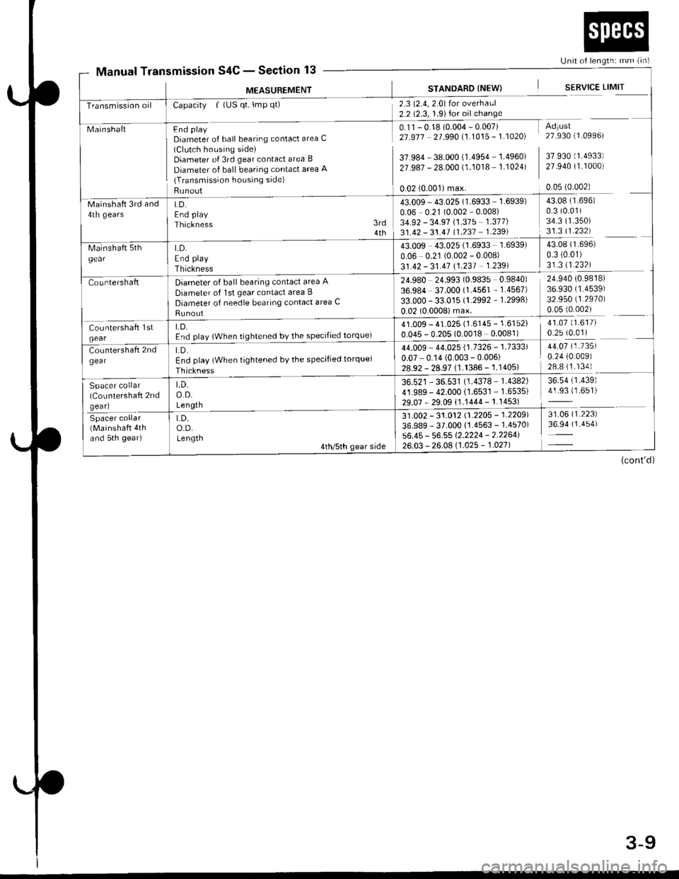
Unit of length: mm (in)
Transmission oil
43.009 43.025 (1.6933 - 1.6939)
0.06 0.21 (0.002 - 0.008)
31.42 - 31.41 \1.231 1.2391
t.D.End play
Thickness
Diameter of ball bearing contact area A
Diameter of lst gear contact area I
Diameter of needle bearing contact area C
Runout
LD.End play {When tightened by the specified torque)
Thickness
LD.o.D.Length
Spacer collar(CoLrntershaft 2ndgear)
Spacer collar(Mainshaft 4thand 5th gear)
LD.o.D.Lengtn
Manual TransmissionS4C - Section 13
M€ASUREMENT
MainshaftFnd plaVDiameter of ball bearing contact area C(Clutch housing side)Diameter of 3rd gear contact area B
Diameter of ball bearing contact area 'q(Transmission housing side)
Runout
Capacity | (US qt, lmp qt)
LD.End play
Thickness
2.3 (2.4,2.0) for overhaul2.2 (2.3, 1.9)for oil change
0.11 - 0.18 (0.004 - 0.007)21 .917 - 21 .990 11.1015 - 1 .10201
37.984 38.000 (1.4954 1.4960)
27.987 - 28.000 (1.1018 1.1024)
STANDARD {NEW)
0.02 (0.001)max.
SERVICE LIMIT
Adtust27.930 (1.0996)
37 930 (1.4933)
27.940 (1.1000)
0.05 (0.002)
Mainshaft 3rd and4th gears
43.009 - 43.025 (1.6933 1.6939)
0.06 - 0.21 (0.002 0.008)
34.92 - 34.91 \1.315 1.311)
31.42 - 31.41 (1.237 1.239)
24.980 24.993 (0.9835 0.9840)
36.984 37.000 (1.4561 - 1.4567)
33.000 - 33.015 (1.2992 - 1.2998)
0.02 (0.0008) max.
3rd4th
43.08 (1.696)
0.3 (0.01)
34.3 ('�t.350)
31.3 11.232)
43.08 (1.696)
0.3 (0.01)
31.311.232)
24.940 (0.9818)
36.930 (1.4539)
32.950 (1.2970)
0.05 (0.002)
41.07 (1.617)
0.25 (0.01)41.009 - 41.025 (1.6145 - 1.6152)
0.045 - 0.205 (0.0018 0.0081)
44.009 44.025 {1.7326 - 1.7333)
0.07 0.14 (0.003 - 0.006)28.92 - 28.97 (1.1386 -'�j.1405)
36.521 - 36.531 (1.4378 1.4382)
41.989- 42.000 (1.6531 - 1.6535)
29.07 - 29.09 11.1444 - 1.1453)
44.07 (1.735)
0.24 (0.009)
28.8 (1.134)
36.54 (1.439)
41.93 (1.651)
31 .0O2 - 31 .012 11 .2205 - 1 .2209'l
36.989 - 37.000 {1.4563 - 1.4570)
56.45 - 56.55 1'2.2224 - 2.2264126.03 - 26.0A 11 .025 - 1 .021 |
31.06 (1.223)
36.94 (1.454)
(cont'd)
3-9
Page 59 of 2189
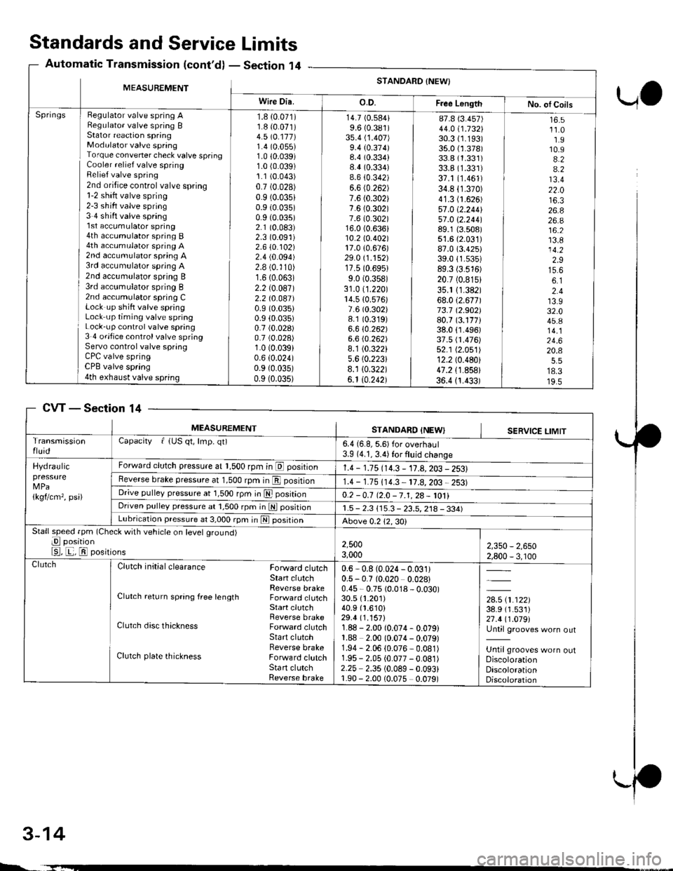
Standards and ServiceLimits
Section '14Automatic Transmission (cont'd)
UO
MEASUREMENTSTANDARD {NEW}
Wire Dia.o.D.Free LongthNo. ol CoilsHegulator valve spring ARegulato. valve spring BStator reaction springModulator valve springTorque convener check valve springCooler relief valve springRelief valve spring2nd oritice control valve spring1-2 shift valve spring2-3 sh ift valve spring3 4 shift valve spring'l st accumulator spring4th accumulator spring B4th accumulator spring A2nd accumulator spring A3rd accumulator spring A2nd accumulator spring B3rd acc!mulator spring B2nd accumulator spring CLock up shift valve springLock up timing valve springLock-up control valve spring3 4 ofifice control valve springServo control valve springCPC valve springCPB valve spring4th exhaust valve spring
Springs1.8 {0.071)1.8 {0.071)4.5 \O.117)1.4 (0.055)
1.0 10.039)1.0 (0.039)
1.1 (0.043)
0.7 (0.028)
0.9 (0.035)
0.9 (0.035)
0.9 (0.035)
2.1 (0.083)
2.3 (0.091)
2.610.102)2.4 (0.094)
2.8 (0.'110)
1.6 (0.063)
2.2 (0.087)
2.2 t0.041)0.9 (0.035)
0.9 (0.035)
0.7 (0.028)
0.7 (0.028)
1.0 (0.039)
0.6 (0.024)
0.9 {0.035)0.9 (0.035)
14.7 (0.584)
9.6 (0.381)
3s.4 (1.407)
9.4 (0.374)8.4 (0.334)
8.4 (0.334)
8.6 {0.342)6.6 (0.262)
7.6 (0.302)
7.6 (0.302)
7.6 (0.302)16.0 (0.636)10.2lo.402l17.0 {0.676)29.0 (1.152)
17.5 (0.6951
9.0 (0.358)
31.0 (1.220)
14.5 {0.576)7.6 (0.302)
8.1 (0.319)
6.610.262)6.6 (0.262)
8.1 (0.322)
5.6 (0.2231
8.1 10.322)6.1 10.242)
87.8 (3.457)
44.0 i.732l'30.3 (1.193)
35.0 {1.378)33.8 (1.331)
33.8 (1.331)
37.1 (1.461)
34.8 (1.370)
41.3 (1.626)
57.0 (2.2441
51 .0 \2.244189.1 {3.508)51.6 (2.031)
87.0 (3.425)
39.011.535)89.3 (3.516)
20.7 (0.815)
35.1 11.382)68.012.671173.7 12.902)80.7 (3.177)38.0 {1.496)37.5 fi.476)52.1 (2.051)
12.2 (0.480)
47.2 {1.858}36.4 {1.433)
16.511.01.910.94.24.213.422.016.326.826.a16.213.814.22.915.66.12.413.932.045.814.124.620.4
18.319.5
CVTSection 14
3-14
MEASUREMENTSTANDARD INEWISERVICE LIMITTransmissionfluidCapacity f {US qt, lmp. qt)6.4 {6.8, 5.6) for overhaul3.9 (4.1, 3.4) for fluid change
Hydraulicpressure
1kgflcm,, psi)
Forward clutch pressure at 1,500 rpm in E position1.4 - 1.15 114.3 - 11.A,203 - 2531Reverse brake pressure at 1,500 rpm in E position1.4 - 1.75 (14.3 11.8,203 2531Dr;ve pulley pressure at 1,500 rpm in E posrtrono.2 -0.7 12.0 -7.1,28- 1011Driven pulley pressure at 1,500 rpm in N positionr.5 - 2.3 115.3 - 23.5, 218 - 334)Lubrication pressure at 3,000 rpm in E posrtronAbove 0.212,30)Stall speed fpm (Check with vehicle on level ground)
E position
E, E, El positions2,5003,0002,350 - 2,6502,800 - 3, r00ClutchClutch initial clearance Forward clutchStart clutchReverse brakeClutch return spring free length Forward clutchStart clutchReverse brakeClutch disc thickness Forward clutchStart clutchReverse brakeClutch plate thickness Forward clutchSta rt clutchReverse brake
0.6 - 0.8 (0.024 - 0.031)0.5 - 0.7 (0.020 0.028)0.45 - 0.75 (0.018 - 0.030)30.5 {1.201)40.9 (1.610)
29.4 (1.157)
1.88 - 2.00 (0.074- 0.079)1.88 2.00 (0.074 - 0.079)1.94 - 2.06 (0.076 - 0.081)1.95 - 2.05 (0.077 -0.081)
2.25 2.35 (0.089 - 0.093)1.90 - 2.00 (0.075 0.079)
,*x.ar}38.9 (1.531)
27.411.019l'Until grooves worn out
Until grooves worn outDiscolorationDiscolorationDiscoloration
L.
Page 625 of 2189

S4C Model ('99 - 00 2-door Si, SiR)
Manual Transmission
Special Tools ............' 13-46
Maintenance
Transmission Oi1 ...................'.......... 13-47
Back-up Light Switch
Repfacement ...""" 13'47
Transmission Assembly
Removal ......'.......... 13-/tB
lnstallation ............. 13-52
lllustrated lndex ................................... 13-54
Transmission Housing
Removal ................. 13-55
Beverse Shift Holder, Reverse ldler Gear
Clearance lnspection ...................".. 13-57
Removal ................. 13-58
Change Holder Assembly
Clearance lnspection .................".... 13-59
Removal ....,,........... 13-61
Disassembly/Reassembly ............... 1 3-62
Mainshaft, Countershaft, Shift Fork
Removal ................. 13-63
Shift Rod
Removal .........."'.... 13-64
Shift Fork Assembly
lndex ................ ...... 13-65
Clearance lnspection .............'......... 13'66
Mainshaft Assembly
lndex ............"" ...... 13-67
Clearance lnspection ....................... 13-68
Disassembly .......... 13-71
fnspection '."'.......', 13'72
Reassembly .......'... 13-73
Countershaft Assembly
fndex ................ "....13-71
Glearance Inspection'......'...........'... 1 3'75
Disassembly .......... 13-76
fnspection .'............13'77
Reassembly "......... 13'78
Synchro Sleeve, Synchro Hub
Inspection .............. 13'8C
Installation ............. 13-80
Synchro Ring, Gear
Inspection .'............ 13-81
Differential
lndex ................ ...... 13-82
Backlash Inspection ..."..........."'...... 1 3-82
Final Driven Gear Replacement ...... 13-83
Bearing Replacement ....."'.......""'.. 13-83
Thrust Shim Adiustment ......""'..... 13-84
Clutch Housing Bearing
Replacement ..'...... 13-86
Mainshaft Thrust Glearance
Adiustment '.........'. 13-88
Transmission
Reassembly ."'....... 13-91
Oil Seals
Replacement ..'...... 13-96
Gearshift Mechanism
Overhaul ................ 13-97
\
Page 630 of 2189
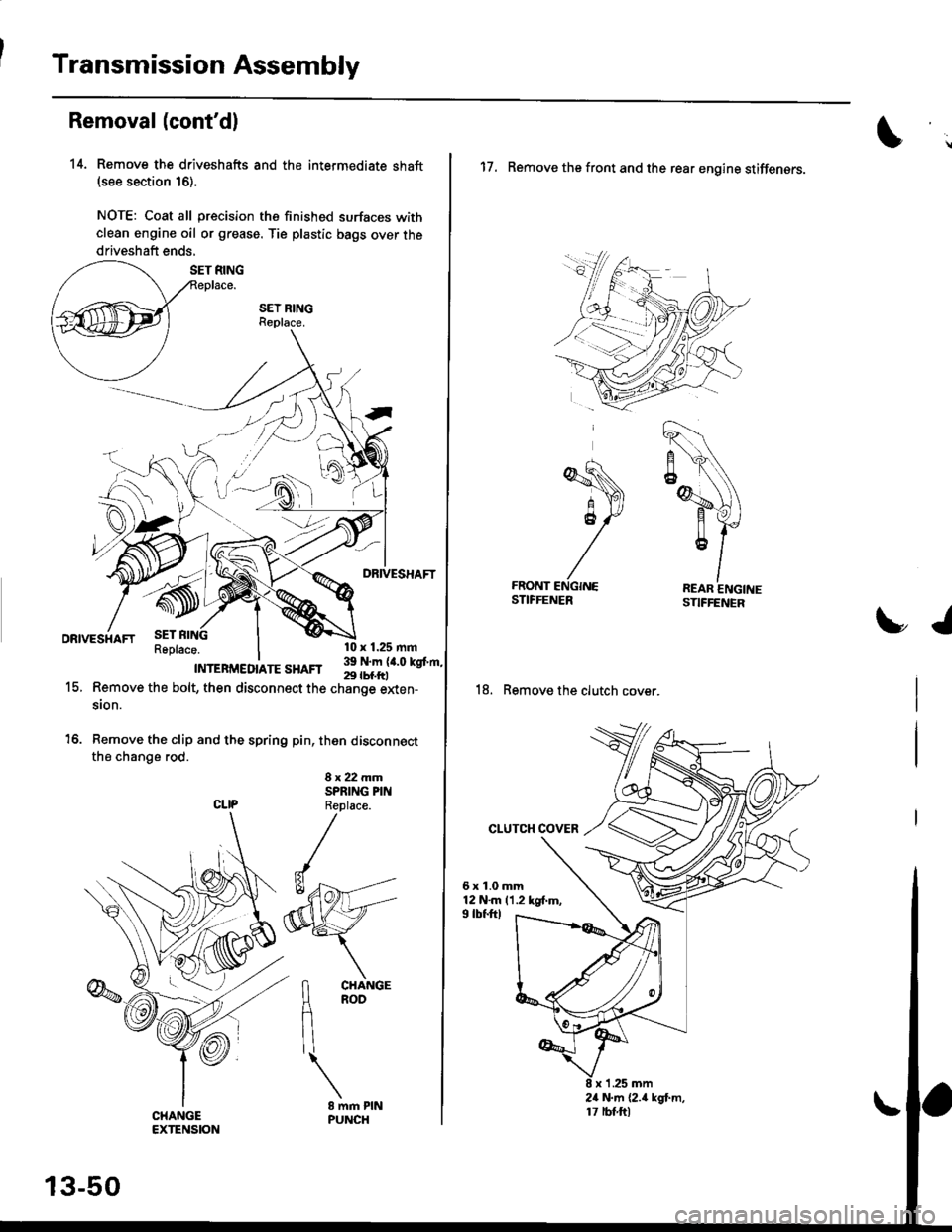
Transmission Assembly
Removal(cont'd)
14. Remove the driveshafts and the intermediate shaft(see section 16).
NOTE: Coat all precision the finished surfaces with
clean engine oil or grease. Tie plastic bags over the
driveshaft ends,
Remove the bolt, then disconnect the change elden-
sion.
Remove the clip and the spring pin, then disconnectthe change rod.
8x22mmSPRING PINCLIP Replace.
15.
13-50
17. Remove the front and the rear engine stiffensrs.
18. Remove the clutch cover.
CLUTCH COVER
6x1.0mm12 N.m (1.2 kg{.m,9 tbf.ftl
x 'l .25 mm
tJ
24 N.m {2.4 kgt m,17 rbt ftl
Page 632 of 2189
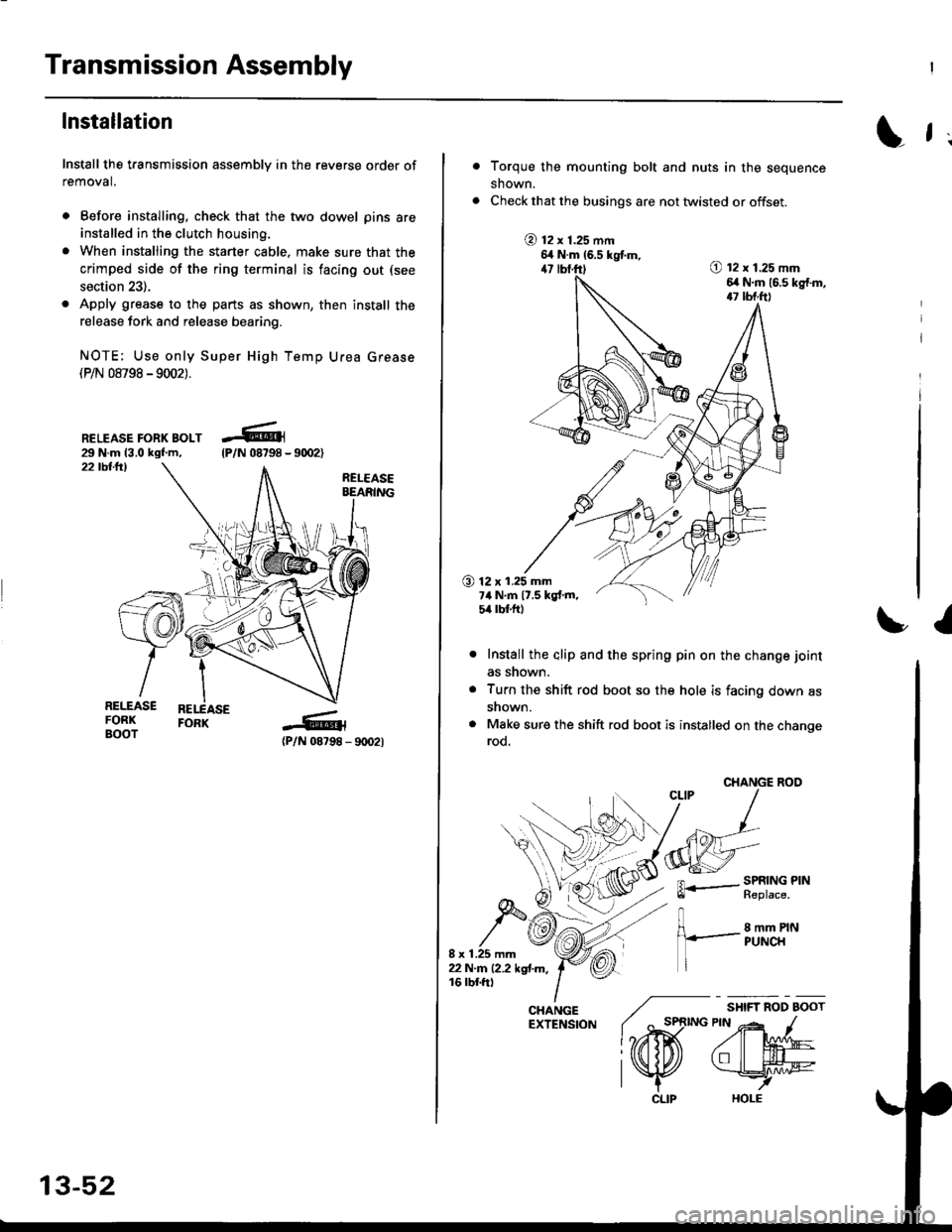
Transmission Assembly
lnstallation
Install the transmission assembly in the reverse order of
removal.
. Before installing, check that the two dowel pins are
installed in the clutch housing.
. When installing the starter cable. make sure that the
crimped side of the ring terminal is facing out (see
section 23).
. Apply grease to the parts as shown, then install the
release fork and release bearing.
NOTE; Use only Super High Temp Urea Grease(P/N 08798 -9002).
RELEASE FORK BOLT29 N.m 13.0 kgf.m,22 tbllrl
(P/N 08798 - 9rD2l
-R1
tP/N 08798 -
13-52
CLIP
L f ;
Torque the mounting bolt and nuts in the sequence
shown.
Check that the busings are not twisted or offset.
@ t2 x 1.25 mm6,t N.m 16.5 kgtm,47 lbf.ft)O t2 x 1.25 mm6,r N.m (6.s kg{.m,17 tbf.ft)
O 12 x 1.25 mm7ilNm17.5kgf.m,5it lbt ft)
I
Install the alip and the spring pin on the change joint
as snown.
Turn the shift rod boot so the hole is facing down as
snown.
Make sure the shift rod boot is installed on the changerod.
CHANGE ROO
FL.- SPRING PINll heptace,
8 mm PINPUNCH
/ "*,*
lo,iD(
CHANGE ./EXTENSfoN ( ^ st
l?rffi
l\K
Page 635 of 2189
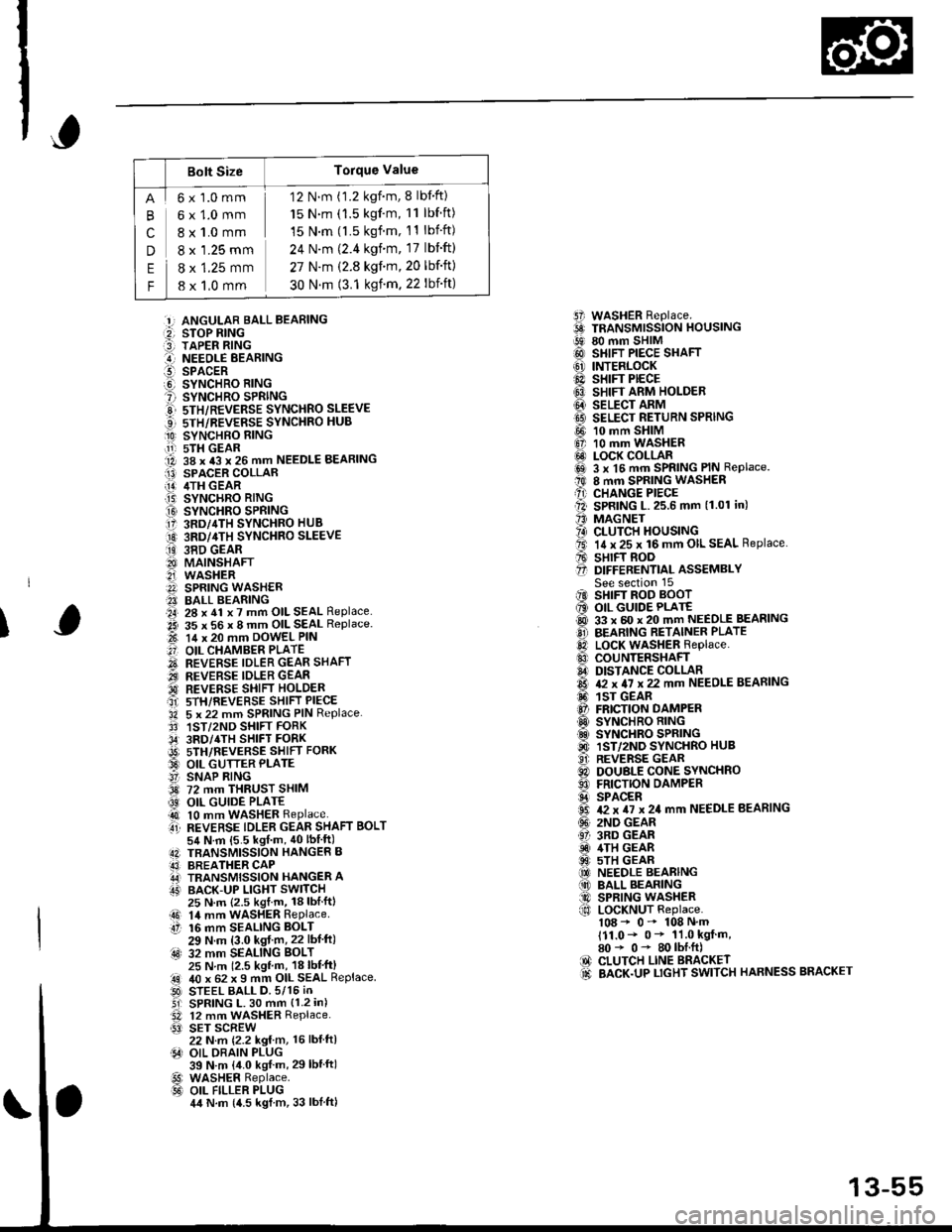
Bolt SizeTorque Value
cn
E
F
6x1.0mm
6x1.0mm
8 x 1.0 mm
8 x '1.25 mm
8 x 1.25 mm
8 x 1,0 mm
12 N.m (1.2 kgnm, 8 lbf'ft)
15 N.m (1.5 kgf'm, 11 lbf ft)
15 N.m (l.5 kgf.m, 11 lbift)
24 N'm (2.4 kgim, 17 lbift)
27 N.m (2.8 kgf.m,20 lbf'ft)
30 N.m (3.1 ksf m. 22 lbift)
5i WASHER Replace.6 TRANSMrssioN HouslNG!9 80 mm SHIM@ SHIFT PIECE SHAFT(6' INTERLOCK@ sHrFr PECE6} SHIFT ARM HOLDER@ seucr nnrvtI9 SELECT RETURN SPRING
@ 10 mm SHIM6, 10 mm WASHER@ LOCK COLLARi6sl 3 x l5 mm SPRING PIN Replace.t0 8 mm SPRING WASHERA) CHANGE PIECEll SPRING L.25.6 mm (1.01 in)'' MAGNET?4) CLUTCH HOUSINGta. 14 x 25 x 16 mm OIL SEAL Replace.A sHrFT BooO D|FFERENT|aL ASSEMBLYSee section 15iIO SHIFT ROD BOOT6 OIL GUIDE PLATE@ 33 x 60 x 20 mm NEEDLE BEASINGO BEARING RETAINER PLATElD LocK WASHER Replace..0 couNTERSHAFIA DISTANCE COLLAR6 & x 4I x 22 mm NEEDLE BEARING6. 1sr GEAR@ FRICTION DAMPERO SYNCHRO RING.d SYNCHRO SPRING@ 1ST/2ND SYNCHRO HUB..9i. REVERSE GEARC) DOUBLE CONE SYNCHROO FRICTION DAMPERS SPACER6 T2 x TI x 24 mm NEEDLE BEARING(!' 2ND GEAR61 3RD GEARiD 4TH GEAR@ 5TH GEAR(O NEEDLE BEARING(10 BALL BEARING@ SPRING WASHERf,o LoCKNUT Replace.108 - 0- 108 N'm111.0- 0* 11.0 kgf m,80* 0- 80lbI.ft)IO CLUTCH LINE BRACKET.d BACK.UP LTGHT SWITCH HARNESS BRACKET
:!, ANGULAR BALL BEABING:2, STOP RING:3] TAPER RING..-I NEEOLE BEARINGl!-- SPACERO SYNCHRO RING? SYNCHRO SPRINGE 5TH/REVERSE SYNCHRO SLEEVE...] sTH/REVERSE SYNCHRO HUB
O SYNCHBO EING.11-r sTH GEAR1A 38 x 43 x 26 mm NEEDLE BEARINGI13) SPACER COLLAR[!] /ITH GEAR.T5) SYNCHRO RING
O SYNCHRO SPRING17 3RD/4TH SYNCHRO HUB
O 3RD/4TH sYNcHRo SLEEVE
ii9 38D GEAR8I MAINSHAFT2i WASHERA SPRING WASH€R?I BALL BEARING.a4, 28 x 41 x 7 mm OIL SEAL Replace..2i 35 x 56 x 8 mm OIL SEAL Replace.t-t 14 x 20 mm DowEL PIN
.'] OIL CHAMBER PLATE
O REVERSE IDLER GEAR SHAFT.iI.., REVERSE IDLER GEAR'd REVERSE SHIFI HOLDERait srH/REVERSE sHIFT PIECE'34 5 x 22 mm SPRING PIN Replace.3' 1ST/2ND SHIFT FORK,34' 3RD/4TH SHIFT FORKi9t) srH/nevense sstrr ronx33 OIL GUTTER PLATE!' SNAP RING3d 72 mm THRUST SHIM
@ OIL GUIDE PLATE4t 10 mm WASHER Replaceti REVERSE TDLER GEAR SHAFT BoLT54 N.m {5.5 kgf m, 40lbIft)4N TBANSMISSION HANGER B43] BREATHER CAPA,J TRANSMISSION HANGER AIT' BACK-UP LIGHT SWITCH
I
25 N.m {2.5 kgl.m, 18lblftl14 mm WASHER RePlaceaO 14 mmtt 16 mm16 mm SEALING BOLT29 N.m (3.0 kgf m,22 lbf ft):4s) 32 mm SEALING BoLT25 N m 12.5 kgl m, 18 lbl'ft)40 x 62 x I mm OIL SEAL ReplaceSTEEL BALL D.5/15 iNSPRING L. 30 mm {1.2 in)12 mm WASHER Replace.SET SCREW22 N.m {2.2 kg{ m, 16 lbl ftlOIL DRAIN PLUG39 N.m {4.0 kgf m, 29lbtftlWASHER Replace.OIL FILLER PLUG4,t N.m {4.5 kgl m, 33 lblftl
.!rl00
@l
13-55
Page 681 of 2189

Description
The automatic transmission is a 3-element torque converter and a dual-shaft electronically controlled unit which provides
4 soeeds forward and 1 reverse.
Torque Convertel, Geats, and Clutches
The torque converter consists of a pump, turbine and stator, assembled in a single unit. They are connected to the engine
crankshaft so they turn together as a unit as the engine turns. Around the outside of the torque converter is a ring gear
which meshes with the starter pinion when the engine is being started. The entire torque converter assembly seryes as a
flywheel while transmiuing power to the transmission mainshaft.
The transmission has two parallel shafts: the mainshaft and the countershaft. The mainshaft is in Iine with the engine
crankshaft. The mainshaft includes the 1st, 2nd and 4th clutches, gears tor 2nd, 4th, reverse and lst (3rd gear is integral
with the mainshaft, while the reverse gear is integral with the 4th gear). The countershaft includes the 3rd clutch, and
gears for 3rd,2nd, 4th, reverse. 1st and park. The gears on the mainshaft are in constant mesh with those on the counter-
shaft. When certain combinations of gears in transmission are engaged by clutches. power is transmitted from the main-
shaft to the countershaft to provide E, ld, E, and E positions.
Electronic Control
The electronic control svstem consists of the Powertrain Control Module {PCM), sensors, a linear solenoid and four
solenojd valves. Shifting and lock-up are electronically controlled for comtonable driving under all conditions. The PCM is
located below the dashboard, under the front lower panel on the passenger's side
Hydraulic Control
The valve bodies include the main vatve body, the secondary valve body, the regulator valve body, the servo body and the
lock-up valve body through the respective separator plates, They are bolted on the torque converter housang
The main valve body contains the manual valve, the 1-2 shift valve. the 2nd orifice control valve, the CPB {Clutch Pressure
Back-up) valve, the modulator valve. the servo control valve, the relief valve, and ATF pump gears The secondary valve
body contains the 2-3 shift valve. the 3-4 shift valve, the 3-4 orifice control valve, the 4th exhaust valve and the CPC (Clutch
pressure Control) valve. The regulator valve body contains the pressure regulator valve, the torque converter check valve,
the cooler relief valve, and the lock-up control valve. The servo body contains the servo valve which is integrated with the
reverse shift fork, and the accumulators. The lock-up valve body contains the lock-up shift valve and the lock-up timing
valve. The linear solenoid and the shift control solenoid valve Ay'B are bolted on the outside of the transmission housing,
and the lock-up control solenoid valve Ay'B is bolted on the outside of the torque converter housing. Fluid from regulator
passes through the manual valve to the various control valves. The clutches receive fluid from their respective teed pipes
or internal hydraulic circuit.
Shift Control Mechanism
Input from various sensors located throughout the car determines which shift control solenoid valve the PCM will activate
Activating a shift control solenoid valve changes modulator pressure, causing a shift valve to move. This pressurizes a line
to one of the clutches, engaging that clutch and its corresponding gear, The shift control solenoid valves A and B are con-
trolled by the PCM.
Lock-up Mechanism
In ,Dt1 position, in 3rd and 4th. and in E position in 3rd, pressurized fluid is drained from the back of the torque converter
through a fluid passage, causing the lock-up piston to be held against the torque converter cover. As this takes place, the
mainshaft rotates at the same as the engine crankshaft. Together with hydraulic control, the PCM optimizes the timing of
the lock-up mechanism. The lock-up valves control the range of lock-up according to lock-up control solenoid valves A and
B, and linear solenoid. When lock-up control solenoid valves A and B activate, the modulator pressure changes The lock-
up control solenoid valves A and B and the linear solenoid are controlled by the PCM.
(cont'd)
14-3