Page 1459 of 2189
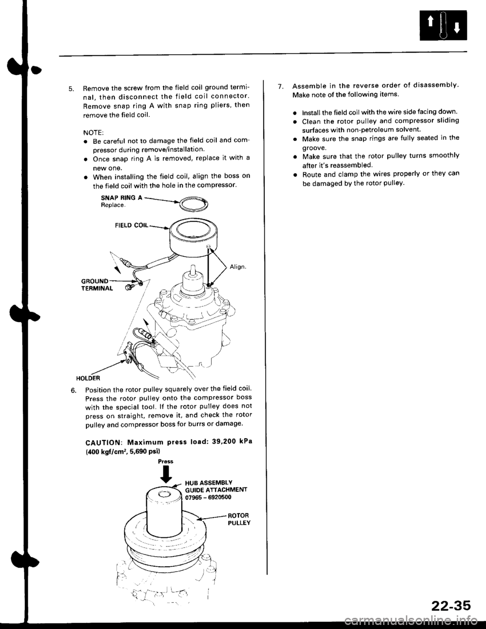
5. Remove the screw from the field coil ground termi-
nal, then disconnect the field coil connector.
Remove snap ring A with snap ring pliers, then
remove the field coil
NOTE:
. Be careful not to damage the field coil and com-
pressor during remove/installation.
. Once snap ring A is removed, replace it with a
new one.
. When installing the field coil, align the boss on
the field coil with the hole in the compressor.
SNAP RING AReplace.
Position the rotor pulley squarely over the field coil.
Press the rotor pulley onto the compressor boss
with the special tool. lf the rotor pulley does not
press on straight, remove it, and check the rotor
pulley and compressor boss for burrs or damage.
CAUTION: Maximum press load: 39,200 kPa
(,[00 kgf/cm'�, 5,590 Psi)
Press
THUB ASSEMBLYGUIDE ATTACHMENT07965 - 6920500
ROTORPULLEY
t'l
i,'
7. Assemble in the reverse order of disassembly
Make note of the following items.
. lnstall the field coil with the wire side facing down.
. Clean the rotor pulley and compressor sliding
surfaces with non-petroleum solvent.
. Make sure the snap rings are fully seated in the
groove.
. Make sure that the rotor pulley turns smoothly
after it's reassembled
. Route and clamp the wires properly or they can
be damaged bY the rotor Pulley.
22-35
Page 1460 of 2189
Compressor (SANDENI
Thermal Protestor Replacement
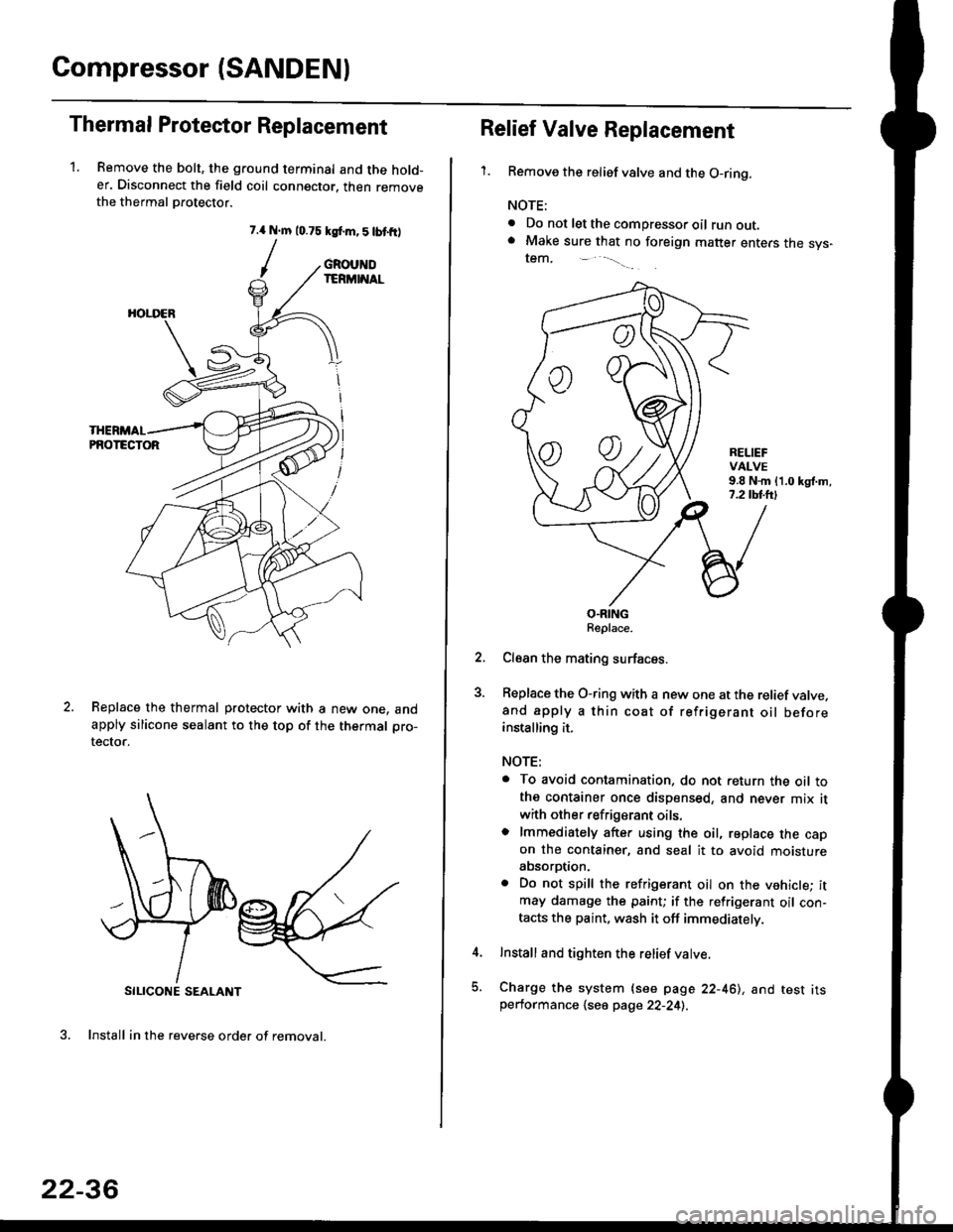
1. Remove the bolt, the ground terminal and the hold-er. Disconnect the field coil connector. then removethe thermal Drotector.
7.{ N.m 10.75 ksf.m,5lbtfr)
/
SILICONE SEALANT
3. Install in the reverse order of removal.
GROUNDIERMINAL
HOI.I'ER
PNOTECTOR
Replace the thermal protector with a new one. andapply silicone sealant to the top of the thermal pro-
tector.
22-36
oo
Relief Valve Replacement
'1.Remove the relief valve and the O-ring.
NOTE:
. Do not let the compressor oil runout.. Make sure that no foreign matter enters the sys-tem,
RELIEFVALVE9.8 N.m {1.0 kgl.m,7.2 tbl.lrl
O.RINGReplace.
Clean the mating surfaces.
Replace the O-ring with a new one at the relief valve.and apply a thin coat of refrigerant oil beforeinstalling it.
NOTE:
. To avoid contamination. do not return the oil tothe container once dispensed, and never mix it
with other refrigerant oils.o lmmediately after using the oil, replace the capon the container, and seal it to avoid moistureabsorption.
. Do not spill the refrigerant oil on the vehicle; itmay damage the paint; if the refrigerant oil con-tacts the paint, wash it off immediately.
Install and tighten the relief valve.
Charge the system {see page 22-461, and test itsperformance 1se6 page 22-241.
Page 1461 of 2189
Compressor (DENSO)
Replacement
1.lf the compressor is marginally operable, run the
engine at idle speed, and let the air conditioning work
for a few minutes, then shut the engine off
Disconnect the negative cable from the battery'
Recover the refrigerant with a recovery/recycling/
charging station lsee page 22-271
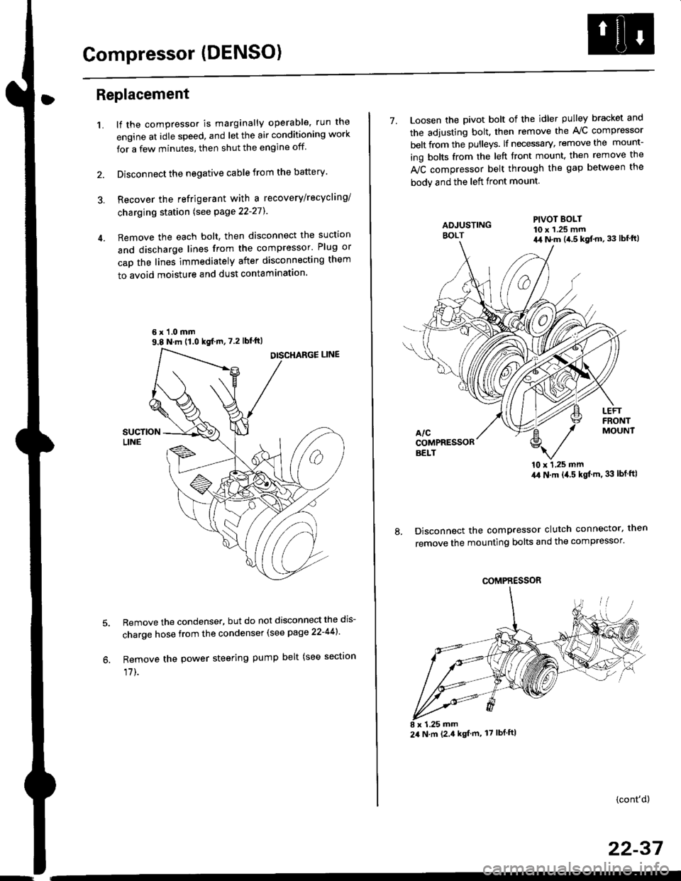
Remove the each bolt, then disconnect the suction
and discharge lines from the compressor' Plug or
cap the lines immediately after disconnecting them
to avoid moisture and dust contaminatlon.
6 x '1.0 mm9.8 N.m (1.0 kgf m,7.2 lbfft)
Remove the condenser, but do not disconnect the dis-
charge hose from the condenser (see page 22-441'
Remove the power steering pump belt (see sectron
17]-.
7. Loosen the pivot bolt of the idler pulley bracket and
the adjusting bolt. then remove the A,/C compressor
belt from the pulleys. lf necessary, remove the mount-
ing bolts from the left front mount. then remove the
fuC compressor belt through the gap between the
bodv and the left front mount.
'10 x 1,25 mm4,0 N.m (,1.5 kgf'm. 33 lbt ftl
Disconnect the compressor clutch connector, then
remove the mounting bolts and the compressor'
PIVOT BOLT10 x 1.25 mm4,1 N.m (4.5 kgt'm,33 lbfft)
COMPRESSOR
24 N.m (2.4 kgf m, 17 lbf ftl
(cont'd)
22-37
Page 1462 of 2189
Compressor (DENSOI
Replacement (cont'd)
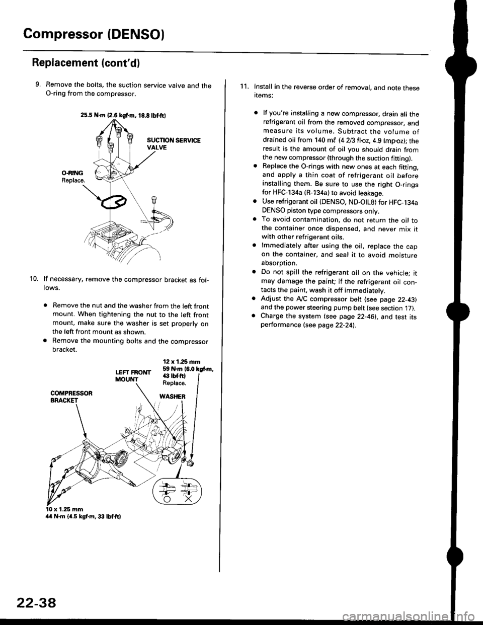
9. Remove the bolts, the suction service valve and theO-ring from the compressor,
lf necessary, remove the compressor bracket as fol-lows.
. Remove the nut and the washer from the left frontmount. When tightening the nut to the left frontmount, make sure the washer is set p.operly onthe left front mount as shown.
a Remove the mounting bolts and the compressor
bracket.
12 x 1,25 rnm59 N.m 16.0 kgfrm,
10.
LEFT FRONTMOUNT€ rbf.fi)Roplace.
WASHEB
x 1.25 mm
2s.5 N.m {2.6 kgf.m. 18.8 tbtttl
4/r N.m {4.5 kgf.m, 33 lbt ft}
22-3A
1 1. Install in the reverse order of removal, and note thesertems:
lf you're installing a new compressor. drain all therefrigerant oil from the removed compressor. andmeasure its volume. Subtract the volume ofdrained oil from '140 ml (4 28 fl{,z, 4.9 lmpoz); theresult is the amount of oil you should drain fromthe new compressor (through the suction fifting).Replace the O-rings with new ones at each fining,and apply a thin coat of refrigerant oil beforeinstalling them. Be sure to use the right O,ringsfor HFC-134a (R-134a) to avoid leakage.
Use refrigerant oil {DENSO, ND-OtL8) for HFC-134aDENSO piston type compressors only.To avoid contamination, do not return the oil tothe container once dispensed, and never mix itwith other refrigerant oils.
lmmediately after using the oil, replace the capon the container, and seal it to avoid moisture
absorption.
Do not spill the refrigerant oil on the vehicle; itmay damage the paint; if the refrigerant oil con-tacts the paint, wash it off immediatelv.
Adjust the ly'C compressor belt (see page 22-43)and the power steering pump belt (see section 17).Charge the system (see page 22-46), and test itsperformance (see page 22-24!..
Page 1464 of 2189
Compressor (DENSOI
Clutch Inspection
Check the plated parts of the pressure plate for colo.changes, peeling or other damage. lf there is dam-age, replace the clutch set.
Check the pulley bearing play and drag by rotatingthe pulley by hand, Replace the clutch set with a newone if it is noisy or has excessive play/drag.
Measure the clearance between the pullev and thepressure plate all the way around. lf the clearance isnot within specified limits, the pressure plate must beremoved and shim(s) added or removed as required,
following the procedure on page 22-41.
Clearanca:0.5 t 0.15 mm {0.020 r 0.006 in}
NOTE: The shims are availabte in three thicknesses:0.1 mm,0.3 mm and 0.5 mm.
22-40
. Check resistance of the field coil. lf resistance is notwithin specifications, replace the field coil.
Fiald Coil Resistanc€: 3.it to 3.8 O at 20.C l68.Fl
Page 1465 of 2189
Clutch Overhaul
1. Remove the center bolt while holding the pressure
olate with the sPecialtool.
CENTER BOLT13.2 N.m (1.35 ksl m, 9.?6 lbf'ft)
A/C CLUTCH HOLOER(Commercially available)
Robinair: P/N 10204
Kent-Moore: P/N J37872
Remove the pressure plate and shim(s). taking care
not to lose the shim{sl.
PAESSUREPLATE
3. Remove the snap ring B with snap ring pliers, then
remove the pulley Be careful not to damage the
pulley and comPressor'
SNAP RING B
Replace.
'.L-)
.'l 5$ f-t
1/---( ll l,
vll/
(cont'd)
22-41
Page 1466 of 2189
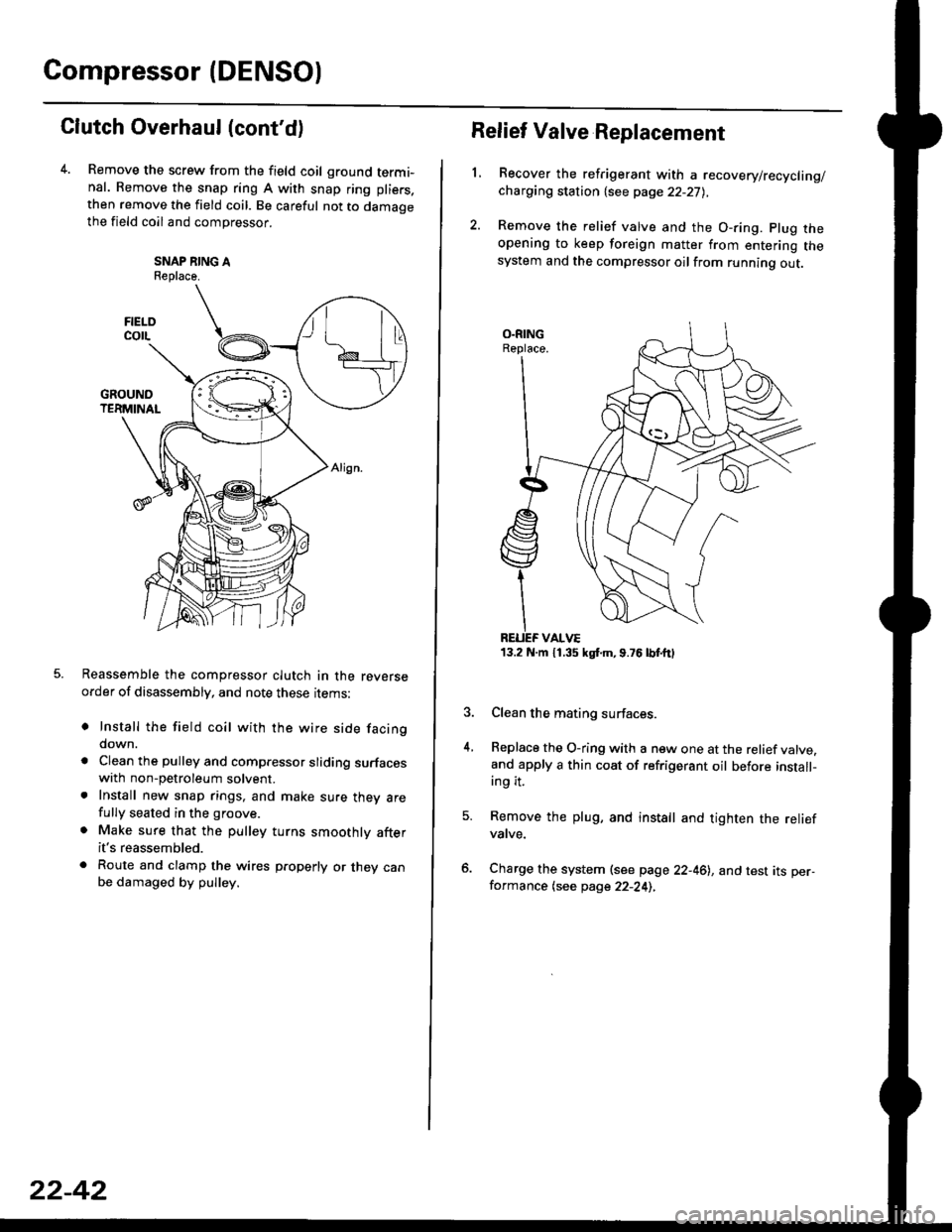
Compressor (DENSO)
Clutch Overhaul (cont'd)
Remove the screw from the field coil ground termi-nal. Remove the snap ring A with snap ring pliers.
then remove the field coil. Be careful not to damaoethe field coil and compressor.
SNAP NING AReplace.
Reassemble the compressor clutch in the reverseorder of disassembly, and note these rrems:
o Install the field coil with the wire side facingdown.
a Clean the pulley and compressor sliding surfaceswith non-petroleum solvent.. Install new snap rings, and make sure thev arefully seated in the groove.
. Make sure that the pulley turns smoothly afterit's reassembled.
. Route and clamp the wires p.operly or they canbe damaged by pulley.
FIELOcorL
22-42
13.2 N.m 11.35 kgt m,9.76lbtttl
Relief Valve Replacement
L
4.
Recover the refrigerant with a recovery/recycling/charging station {see page 22-27),
Remove the relief valve and the O-ring. plug theopening to keep foreign matter from entering thesystem and the compressor oilfrom running out.
Clean the mating surfaces.
Replace the O-ring with a new one at the relief valve.and apply a thin coat of refrigerant oil before install-ing it.
Remove the plug, and install and tighten the reliefvatve.
Charge the system (see page 22-46), and test its per-formance (see page 22-24),
Page 1467 of 2189
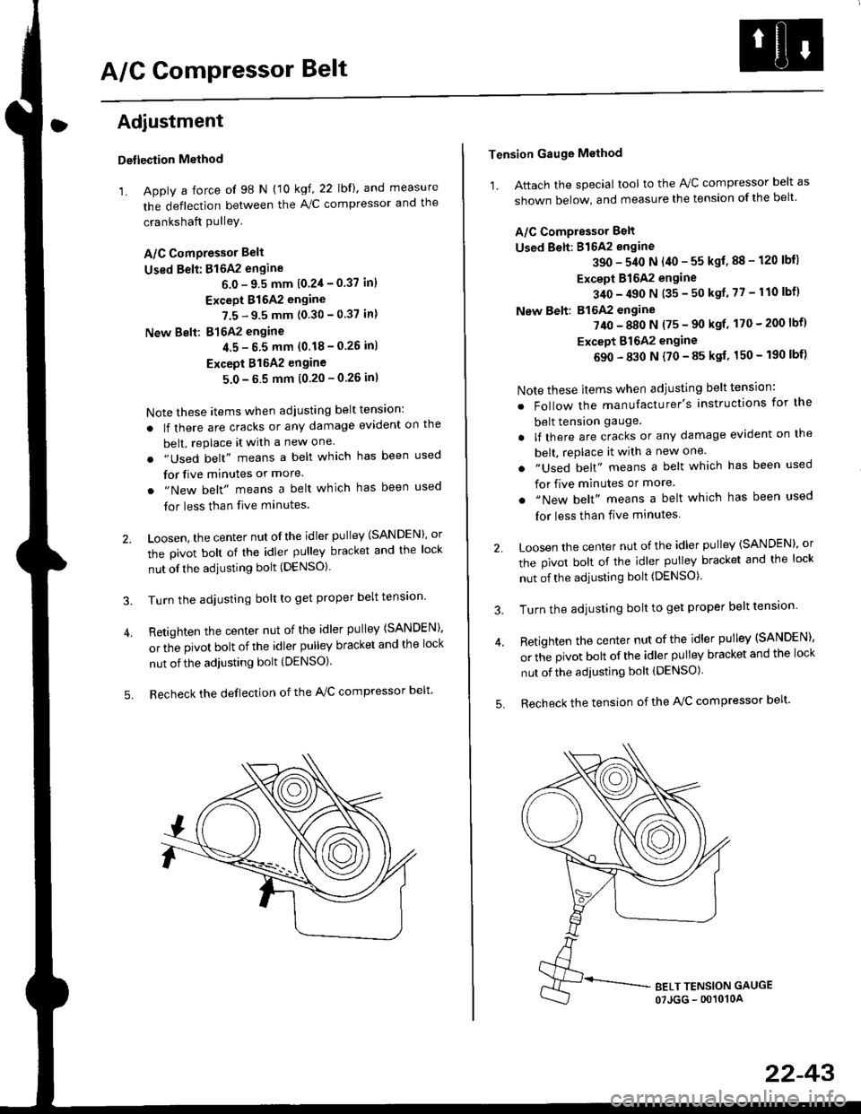
A/G GomPressor Belt
Adjustment
Detlection Method
'1. Apply a force of 98 N (10 kgf, 22 lbf), and measure
the deflection between the A,/C compressor and the
crankshaft PulleY
A/C ComPressor Belt
Used Belt: 816A2 engine
6.0 - 9.5 mm 10 2'l - 0.37 inl
Except 816A2 engine
7.5 - 9.5 mm (0.30 - 0.37 in)
New Belt: 816A2 engine
4.5- 6 5 mm (0.18-0.26 in)
Except 815A2 engine
5.0-5 5 mm (0.20-0.26 inl
Note these items when adjusting belt tens'on:
. lf there are cracks or any damage evident on the
belt, replace it with a new one.
. "Used belt" means a belt which has been used
for five minutes or more.
. "New belt" means a belt which has been used
tor less than five minutes.
2. Loosen, the center nut ofthe idler pulley (SANDEN), or
the pivot bolt of the idler pulley bracket and the lock
nut ofthe adjusting bolt (DENSO).
3. Turn the adjusting bolt to get proper belt tension'
4. Retighten the center nut of the idler pulley (SANDEN),
or the pivot bolt of the idler pulley bracket and the lock
nut of the adjusting bolt (DENSO).
5. Recheck the deflection of the A,/C compressor belt'
Tension Gauge Method
1. Attach the special tool to the IVC compressor belt as
shown below, and measure the tension of the belt
A/C Compressor Belt
Used Belt: 816A2 engine
390 - 540 N (40 - 55 kgf, 88 - 120 lbll
Except 816A2 engine
340 - 490 N (35 - 50 ksf, 77 - 110 lbfl
New Belt: B16A2 engine
?40 - 880 N {75 - 90 ksf' 170 - 200 lbf)
Except Bl642 engine
690 - 830 N (70 - 85 ksf, 150 - 190 lbf)
Note these items when adjusting belt tension:
. Follow the manufacturer's instructions for the
belt tension gauge.
. lf there are cracks or any damage evident on the
belt, rePlace it with a new one.
. "Used belt" means a belt which has been used
for five minutes or more.
. "New belt" means a belt which has been used
for less than five minutes
2 Loosen the center nut of the idler pulley (SANDEN)' or
the pivot bolt of the idler pulley bracket and the lock
nut of the adjusting bolt (DENSO).
3. Turn the adjusting bolt to get proper belt tension
4. Retighten the center nut of the idler pulley (SANDEN),
or the pivot bolt of the idler pulley bracket and the lock
nut of the adjusting bolt (DENSO)
5. Recheck the tension of the A/C compressor belt'
22-43