Page 1288 of 2189

Interior
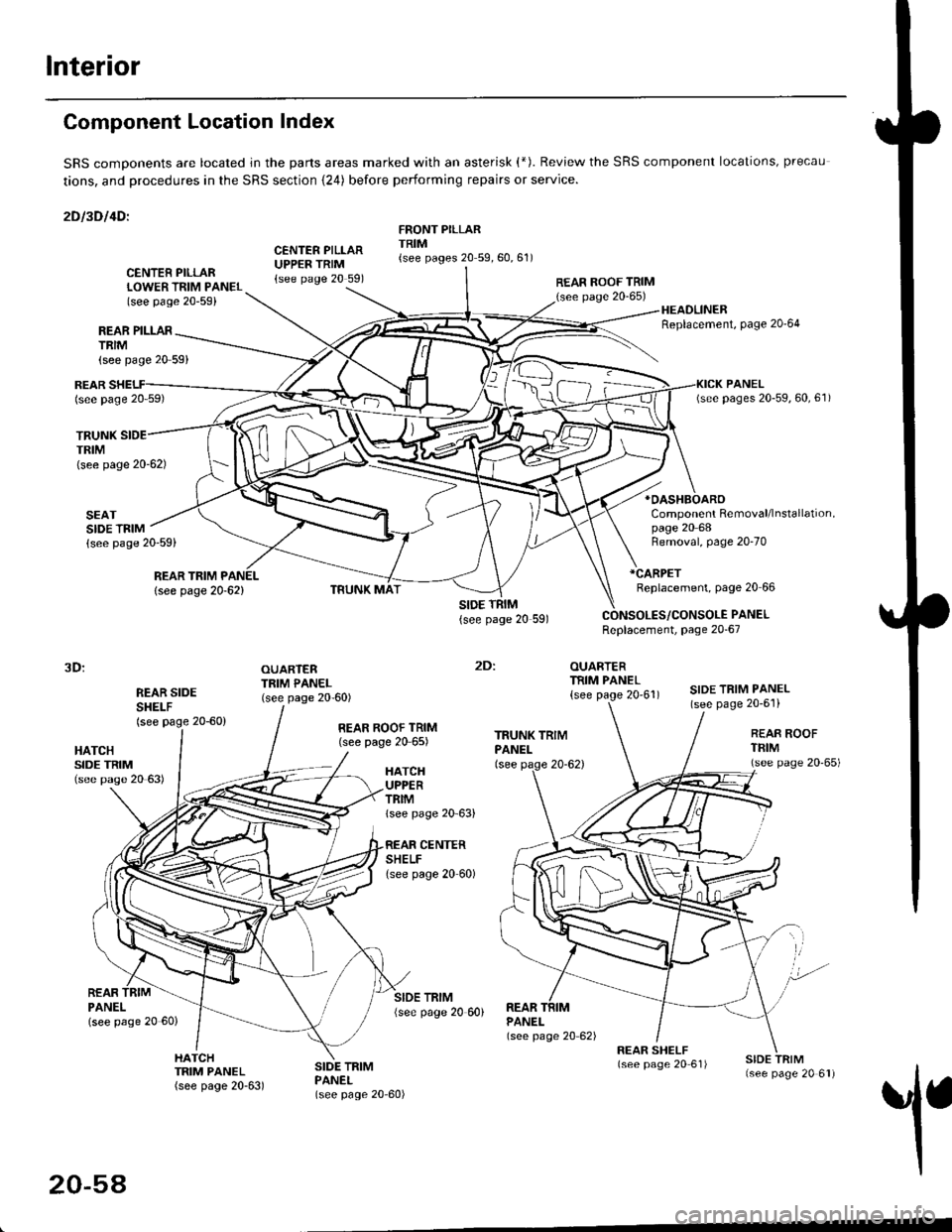
Component Location Index
SRS comDonents are located jn the parts areas marked with an asterisk (*). Review the SRS component locations, precau
tions, and procedures in the SRS section {24) before performing repairs or service.
2Dl3Dl4Dl
CENTER PILLARUPPER TRIM{see page 20 591
FRONT PILLARTRIM{see pages 20 59,60,61)
REAR PILLARTRIM
TRUNKTRIM(see page 20-62)
SEATSIDE TRIM{see page 20-59)
{see page 20 59}
CENTER PILLARLOWER TRIM PANEL(see page 20-59)
REAR ROOF TRIM(see page 20-65)
:
OUARTERTRIM PANEL
{see page 20'61)
HEADLINERReplacement, Page 20'64
*OASHBOARO
Component Removal/lnstallation,page 20 68
REARlsee page 20 59)
REAR TRIM PANEL
lsee page 20-62)
Removal, page 20-70
*CARPET
Replacement, page 20 66
PANELReplacement, page 20-67
3D:
REAR SIDESHEI-F(see page 20-60)
OUARTERTRIM PANEL(see page 20-60)SIDE TRIM PANEL(see page 20-6'l)
2Dl
HATCHSIDE TRIM(see pase 20 63)
REAR ROOF TRIM(see page 20 65)REAR ROOFTFIM(see page 20'65)HATCHUPPERTRIMlsee page 20 63)
CENTERSHELFlsee page 20 60)
REARPANELlsee page 20 60)
SIDE TRIM{see page 20 60)REARPANEL(see page 20 62)
1
HATCHTRIM PANEL(see page 20-63)
SIDE TRIMPANEL(see page 20-60)
20-54
Page 1292 of 2189
Trunk Trim
Replacement
CAUTION:
. Put on gloves to proteci your hands.
. When prying with a flat-tip screwdriver, wrap it with protestive tap€ lo prevent damage.
NOTE:
. Take care not to bend or scratch the trim and panels.
. When removing the trunk side trim or trunk trim panel, fold the seat-back forward.
Japan-produced:
4D: RIGHT TRUNKSIDE TRIM
TRUNK MAT
1B
REAR TRIMPANEL
>: Clip locationsa>,6
a:-) ,2
I g cLlP ^
l#srq-'
| ' |NNER\- crLP
B >,6
NOTE: Do not push
the inner clip in too far.
IJ
LTro
i ) :Hook locations
A i--) , r
' 2D:
TRUNK TRIM
Installation is the reverse of the removal procedure.
NOTE:
. lf necessary. replace any damaged clips.
. To install the A clips. pull the inner clip up. install
the clip, then push the inner clip until it's flush.
(
,- --
/'/ \--
/ --
20-62
Page 1318 of 2189

Rear Seat Belt
Replacement
CAUTION: Chack the rear seat belts for damage, and
replace them if necessary, 8e carolul not to damage
lhem during removal and installation.
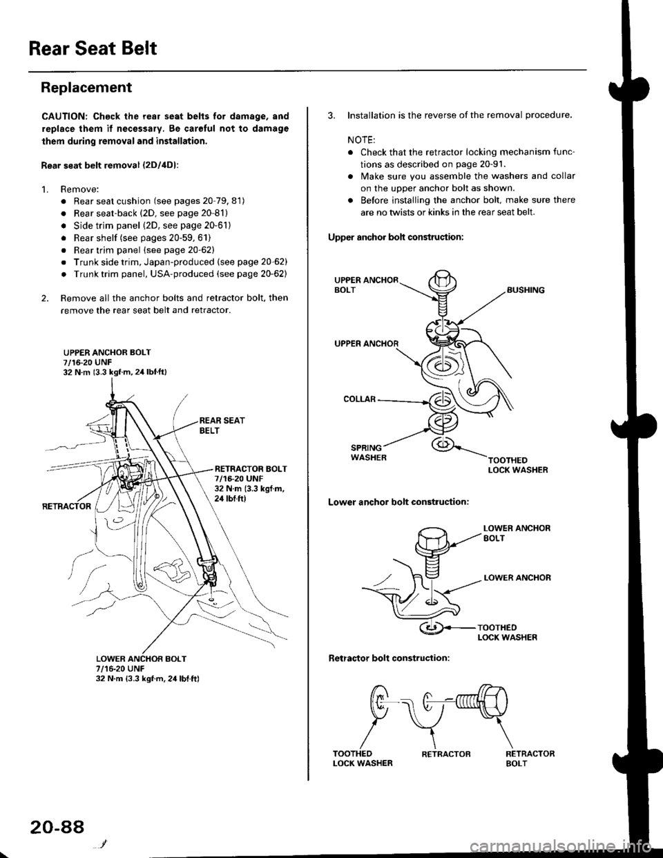
Rear seat belt removal {2Dl4D}:
1. Remove:
. Rear seat cushion (see pages 20-79, 81)
. Rear seat-back (2D, see page 20-81)
. Side trim panel (2D, see page 20-61)
. Rear shelf (see pages 20-59,61)
. Rear trim panel {see page 20-62}
. Trunk side trim, Japan-produced (see page 20-62)
. Trunk trim panel, USA-produced (see page 20-62)
2. Remove all the anchor bolts and retractor bolt, then
remove the rear seat belt and retractor.
UPPER ANCHOR BOLT7/16-20 UNF32 N.m (3.3 kgf.m,2,1 lbtft)
RETNACTOR BOLT7/1F20 UNF32 N.m {3.3 kgf.m,24 tbt.ft)
7/16-20 UNF32 N.m {3.3 kgf.m,24lbt.ft)
20-88
R€TRACTOB
3. Installation is the reverse of the removal procedure.
NOTE:
. Check that the retractor locking mechanism func-
tions as described on page 20-91.
. lvlake sure you assemble the washers and collar
on the upper anchor bolt as shown.
. Before installing the anchor bolt. make sure there
are no twists or kinks in the rear seat belt.
Upper anchor boh condruqtion:
SPRINGWASHER
Lower anchor bolt construction:
LOWER ANCXOREOLT
LOWER ANCHOR
Retractor bolt construction:
RETRACTORBOLT
t7 /7--^,l/rn .----. A -nrfi|lH \
tr\7-\
/\TOOTHEDLOCK WASHER
Page 1338 of 2189

Opener Cables
Replacement
NOTE:
t When removing the clips. use a clip remover.. Take care not to bend the opener cables.
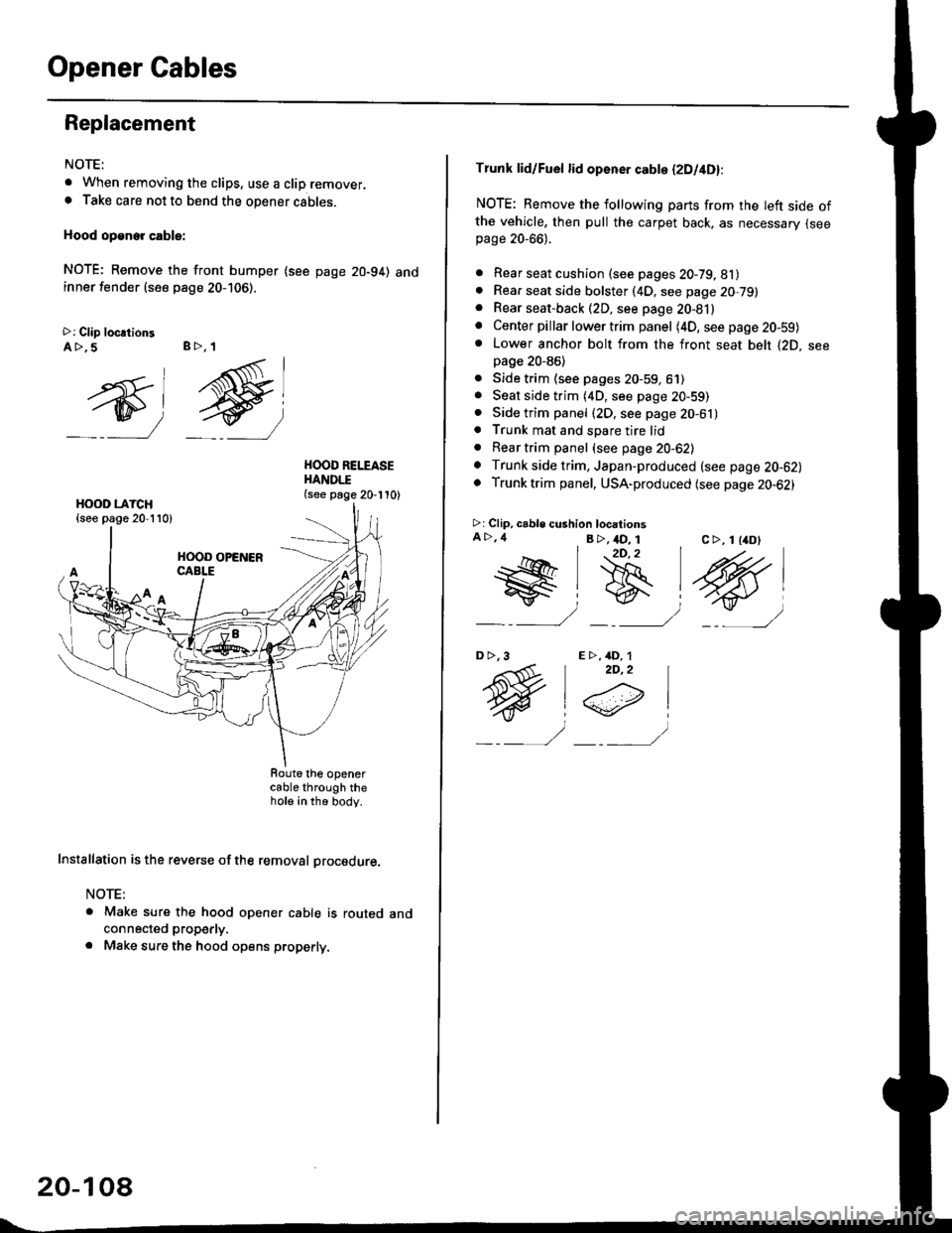
Hood op€ne. cable:
NOTE; Remove the front bumper (see page 20-94) andinner fender (see page 20-106).
>: Clip loc.tionsA >,5 B>, 1
ry)
g
HOOD REI.TASEHANDI.I(see page 20-110)
cable through thehote in th6 body.
Installation is the reverse of the removal procedure.
NOTE:
a Make sure the hood opener cable is routed andconnected properly.
. Make sure the hood opens properly.
20-10a
Tlunk lid/Fuel lid opener cabte (2Dl4D):
NOTE: Remove the following parts from rhe Ieft side ofthe vehicle, then pull the carpet back, as necessary {seepage 20-66).
. Rear seat cushion (see pages 20-79, 81). Rear seat side bolster (4D, see page 20,79). Rear seat-back (2D, see page 20-81). Center pillar lower trim panel (4D, seepage20-59)o Lower anchor bolt from the front seat belt {2D. seepage 20-86)
. Side trim (see pages 20-59, 61). Seat side trim (4D, see page 20-59). Side trim panel (2D, see page 20-61). Trunk mat and spare tire lid. Reartrim panel (see page 20-62). Trunk side trim, Japan-produced (see page 20-62). Trunk trim panel, USA-produced (see page 20-62)
>r Clip, cable cushion locationsA >,4 B >,4D_ 1c >, 1 l4D)2D,2
t@#lB
_ : _/ _-___)
E >,4D, 12D,2
@i
_ _,, -/
D>,3
Page 1342 of 2189

Opener and Latch
Replacement (cont'd)
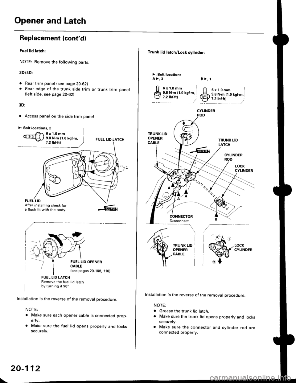
Fuel lid latch:
NOTE: Remove the following pa(s.
2D l4Dl
. Rear trim panel (see page 20-62J. Rear edge of the trunk side trim or trunk trim panel(left side, see page 20-62)
3D:
. Access panel on the side trim panel
FUEL I-IO LATCH
II
FUEL LID OPENERCABLE(see pages 20,108, 1'10)
FUEL LID LATCHRemove the fuel lid latchby turning it 90o
Installation is the reverse of the removal procedure.
NOTE;
o Make sure each opener cable is connectedelty
. Make sure the fuel lid opens properly andsecurely.
prop-
locks
>: Eolt locations, 2 |r'- 6x10mm9.8 N.m (1.0 kgf.m, I
FUEL LIDAfter installing check fora flush fit with the body.
\
20-112
Trunk lid latch/Lock cylinder:
>: Bolt locationsA >,3
6x1.omm i9.8 N.m (1.0 kgf.m,
:::^ _=)
TRUNK LIDOPENER
CONNECTORDisconnect.-\
TRUNK LIDOPENERCABLE
8>, 1
ff e rt.omm IZS 9.8 N.ln (1.0 kgt m,.ty 7.2-tbr.ftt ,/
CYLINOER
TRUNK LIDLATCH
CYLINDERROD
Installation is the reverse of the removal procedure.
NOTE:
. Grease the trunk lid latch.. Make sure the trunk lid opens properly and lockssecurely.
a Make sure the connector and cylinder rod areconnected property.