Page 1142 of 2189

Front Damper
Disassembly/lnspection
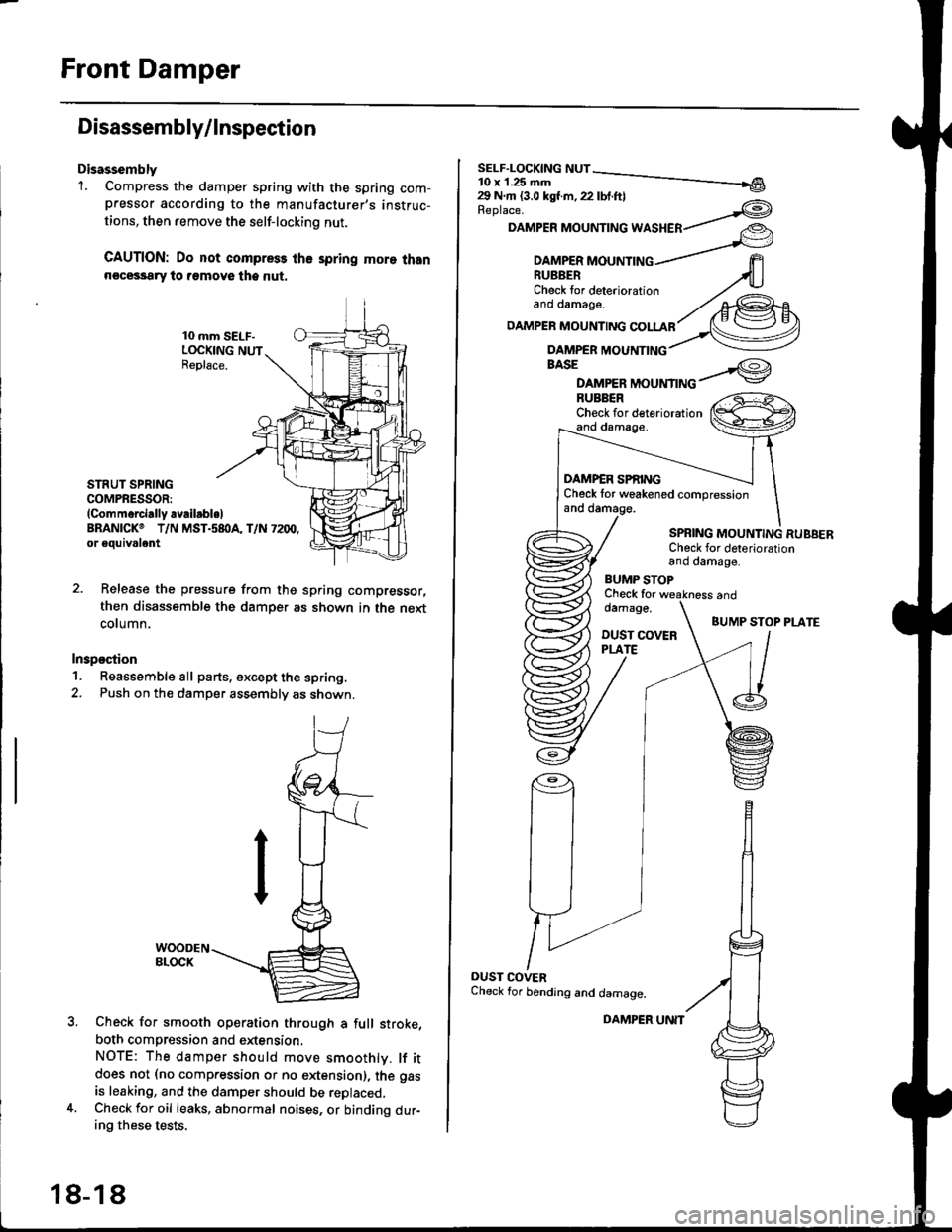
Disassembly'1. Compress the damper spring with the spring com-pressor according to the manufacturer,s instruc-
tions, then remove the self-lockino nut.
CAUTION: Do not compress the spring more thann€cessary to remove the nut.
10 mm SELF-LOCKING NUTReplace.
STRUT SPRINGCOMPRESSOR:(Commerci.lly availabl.lBRANICKO T/N MST.s8I}A, T/N 7200,or eouivalent
Release the pressure from thg spring compressor,
then disassemble the damper as shown in the next
column.
Inspostion
1. Reassemble all parts, except the spring.
2. Push on th€ damper assembly as shown.
Check for smooth operation through a full stroke,
both compression and extension,
NOTE: The damper should move smoothlv. lf itdoes not (no compression or no extension), the gas
is leaking, and the damper should be replaced.Check for oil leaks, abnormal noises, or binding dur-ing these tests.
18-18
DAMPER UNIT
Replace.
DAMPER MOUNTING WASHER
BASE
DAMPER MOUNTINGBUBBERCheck for deteriorationand damage.
DAMP€R SPf,INGCheck tor weakened compressionand damage.
SPBING MOUNTING RUBBERCheck for deteriorationand damage,
BUMP STOPCheck fordamage.
DUST COVERPLATE
and
BUMP STOP PLATE
OUST COVERCheck for bending and damage.
Page 1143 of 2189
\Reassembly
2.
't.
lr
Install the damper unit on a spring compressor.
Assemble the damper in reverse order of removal
except the damper mounting washer and self lock-
ing nut.
NOTE: Align the bottom of the damper spring and
spring lower seat as shown.
STRUTSPRING COMPRESSOR:
lcommercially availablelBRANICK@ T/N MST.58OA, T/N 7200,
or 6quival€nt
SPBING LOWER SEAT
Position the damper mounting base onto the
damper unit as shown.
Compress the damPer sPring.
Install the damper mounting rubber, damper mount-
ing washer, and a new 10 mm self-locking nut.
Hold the damper shaft. and tighten the 10 mm self-
locking nut.
SELF-LOCKING NUT10 x 1.25 mm29 N.m 13.0 kgf m, 22 lbf ft)
3.
4.
Replace.
DAMPERMOUNTING WASHER
(l-t
lnstallation
1. Loosely install the damper onto the frame with the
aligning tab facing inside. then loosely install the
two flange nuts.
FLANGE NUTS10 x 1 ,25 mm49 N.m (5.0 kgt'm, 36 lbf'ftl
DAMPER ASSEMBLY
{cont'd)
18-19
Page 1151 of 2189
IDisassembly/lnsPection
lr
Disassembly
1. Compress the damper spring with the spring com-
pressor according to the manufacturer's instruc-
tions, then remove the self-locking nut.
GAUTION: Do not compress the spring more than
necessary to remove the sell-locking nut.
STNUT SPRING COMPRESSOR:
lComm6rcially .vailablelERANICKo T/N MST-580A, T/N 7200, or equivalent
Release the pressure from the spring compressor.
then disassemble the damper as shown on page 18-
(|-r
lnspection
1. Reassemble all parts, except the sprlng.
2. Push on the damPer as shown.
WOODEN BLOCK
Check for smooth operation through a full stroke,
both compression and extension.
NOTE: The damper should move smoothly lf it
does not (no compression or no extension), the gas
is leaking, and the damper should be replaced.
Check Jor oil leaks, abnormal noises, and binding
during these tests.
{cont'd)
18-27
Page 1152 of 2189

Rear Damper
Disassembly/lnspection (cont'dl
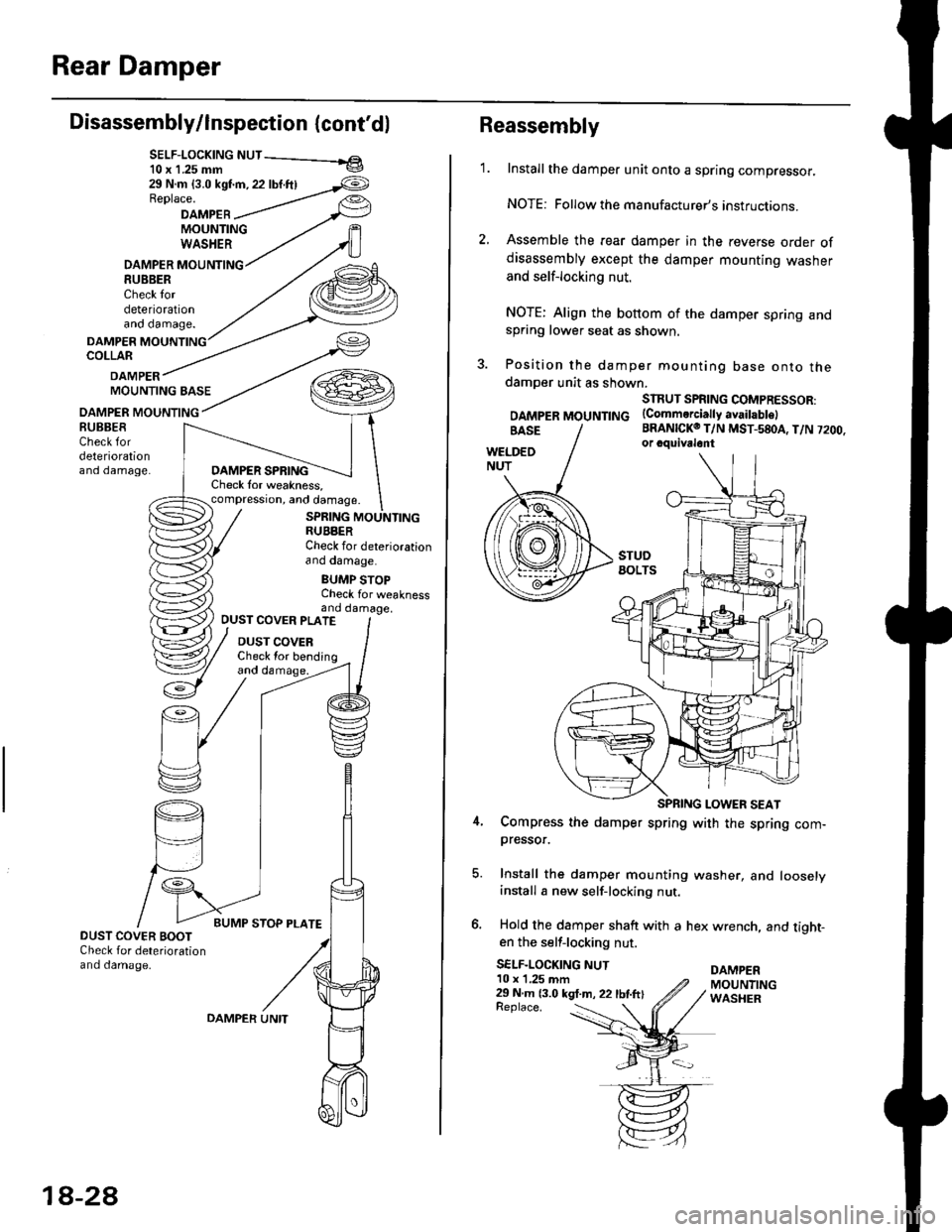
SELF-LOCK|NG NUT - el10 x 1.25 mm v
29 N.m {3.0 kst'm, 22 lbf.ftlReplace.
DAMPEBMOUNTINGWASHER
DAMPER MOUNTING8U8BERCheck tordeteriorationano oamage.
DAMPERCOLLAR
DAMPERMOUNTING BASE
OAMPER MOUNTING
DAMPER SPRINGCheck lor weakness,compression, and damage.
SPRING MOUNTINGRUBBERCheck for deteriorationano oamage.
BUMP STOPCheck for weaknessand damage,
BUBBESCheck fordeteriorationano oamage.
OUST COVER PLATE
DUST COVERCheck lor bending
DUST COVER BOOTCheck for deteriorationand damage.
18-2A
OAMPER UNITReplace. :
Reassembly
1.Install the damper unit onto a spring compressor.
NOTE: Followthe manufacturer's instructions.
Assemble the rear damper in the reverse order ofdisassembly except the damper mounting washer
and self-locking nut.
NOTE: Align the bottom of the damper spring andspring lower seat as shown.
Position the damper mounting base onto thedamoer unit as shown.
SIRUT SPRING COMPRESSOR:
DAMpERMOUNTTNG (Commerciattyavaitabtel
BRANICKO T/N MST-580A, T/N 7200.or cquivalont
Compress the damper spring with the spring com-pressor.
Install the damper mounting washer, and looselyinstall a new self-locking nut.
Hold the damper shaft with a hex wrench, and tight-en the self-locking nut.
SELF-LOCKING NUTDAMPER10 x 1,25 mm29 N m 13.0 kgt.m, 22 lbtftlMOUNTINGWASHER
Page 1156 of 2189
Special Tools
Ref. No. I Tool Numbo]DescriplionOty I Page Reference
o07HAE - SG00100
07JAG - SD40100
07914 - SA50001
Brake Spring Compressor
Pushrod Adjustment Gauge
Snap Ring Pliers
19-28, 33
19-22
o@
19-2
Page 1177 of 2189

Brake Booster InsPection
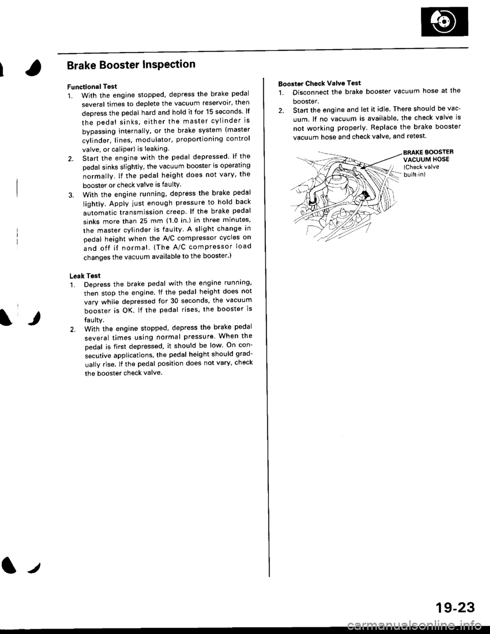
FunctionalTest
1. With the engine stopped, depress the brake pedal
several times to deplete the vacuum reservoir, then
depress the pedal hard and hold it for 15 seconds lf
the pedal sinks' either the master cYlinder is
bypassing internally, or the brake system (master
cylinder. lines. modulator, proportioning control
valve, or caliPer) is ieaking.
2. Start the engine with the pedal depressed lf the
pedal sinks slightly, the vacuum booster is operating
normally. lf the pedal height does not vary, the
booster or check valve is faultY.
3. With the engine running. depress the brake pedal
lightly. Apply just enough pressure to hold back
automatic transmission creep. lf the brake pedal
sinks more than 25 mm (1.0 in.) in three minutes,
the master cvlinder is faulty. A slight change in
pedal height when the A'lC compressor cycles on
and off if normal. (The A/C compressor load
changes the vacuum available to the booster')
Leak Test
1. Depress the brake pedal with the engine running.
then stop the engine. lf the pedal height does not
vary while depressed for 30 seconds, the vacuum
booster is OK. lf the pedal rises. the booster is
faulty.
2, With the engine stopped, depress the brake pedal
several times using normal pressure When the
Dedal is first depressed, it should be low On con-
secutive applications, the pedal height should grad-
uallv rise. lf the pedal position does not vary, checK
the booster check valve.
l./
19-23
Booster Check Valve Test
1. Disconnect the brake booster vacuum hose at the
booster.
2. Stan the engine and let it idle. There should be vac-
uum. lf no vacuum is available, the check valve is
not working properly. Replace the brake booster
vacuum hose and check valve, and retest.
BRAKE BOOSTERVACUUM HOSE(Check valve
built-in)
Page 1182 of 2189
Rear Brake Galiper
Disassembly (cont'd)
7. Remove the piston by rotating the piston counter-clockwise with the tool, and remove the piston
boot.
CAUTION: Avoid damaging the piston.
PISTON BOOTReplace.
Remove the piston seal.
CAUTION: Take care not to damage the cylinderbore.
CALIPER BODYCheck for scoring on
9. Install the special tool between the caliper bodv andspnng cover.
CAUTION: Be caretul not to damags the inside ofthe caliper cylinder during caliper disassembty.
BRAKE SPRINGCOMPRESSOR07HAE - SG00100
11.
LOCKNUTS
Position the locknuts as shown. then turn the shaftuntil the plate just contacts the caliper body.
NOTE: Do not compress the spring under thespring cover.
Turn the shaft clockwise 1/4 -'ll2 tu.n to comoressadjusting spring B in the caliper body.
CAUTION: To preyant damage to the inner compo-nonts. do not turn the shaft mor€ than 1/2 turn.
SHAFT
LOCKNUTS
PISTON SEALReplace.
ADJUSTII{GSPRING 8
19-28
Page 1425 of 2189

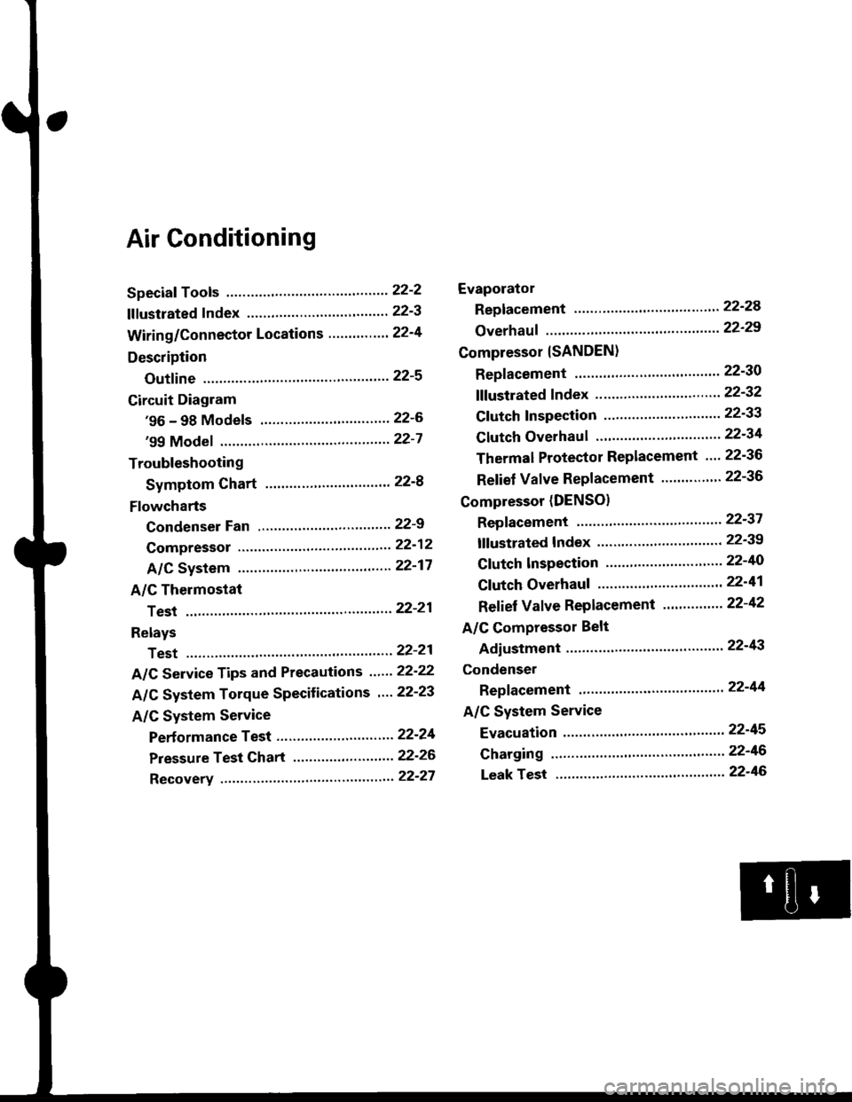
Air Conditioning
Speciaf Tools ......'.....' 22-2
f f f ustrated f ndex ......................... ".......' 22-3
Wiring/Connector Locations'.........'.... 22'4
Description
Outfine ............ .......22-s
Circuit Diagram
'96 - 98 Models ......"..........".......'.... 22-6
'99 Modef """""""' 22-7
Troubleshooting
Symptom Chart ".'......""................. 22-8
Flowcharts
Condenser Fan .........".................,..'. 22-9
Compressor .....""" 22-12
A/C System .........'.22'17
A/C Thermostat
Test ........'.......' """'22'21
Relays
Test ....."'......... ..""'22-21
A/C Service Tips and Precautions ......22-22
A/C System Torque Specifications '...22-23
A/C System Service
Performance Test ... '."......... ".... ....'..22-24
Pressure Test Chart .................. .... "' 22-26
Recovery ...".........," 22-27
Evaporator
Replacement .....",' 22'24
Overhauf .....-.....""' 22'29
Compressor {SANDEN}
Repf acement ......'.' 22-30
fffustrated fndex ......"..................'.... 22'32
Cf utch Inspection ......... "............ ...... 22-33
Clutch Overhau I ........................ ....... 22-34
Thermal Protector Replacement .... 22-36
Relief Valve Replacement ......'..."". 22-36
Compressor (DENSO)
Repfacement ..""',' 22-37
lf lustrated Index ............................... 22-39
Clutch lnspection ............."'...... "'.... 22-40
Cf utch Overhaul .....................'......... 22-41
Ref ief Valve Replacement'..'......"'.. 22-42
A/C Compressor Belt
Adiustment ............22'43
Condenser
Repfacement .......,,22'44
A/C System Service
Evacuation ...,,,.......22-45
Charging '..........--'..22'46
Leak rest """""""'22-46