Page 1887 of 2189
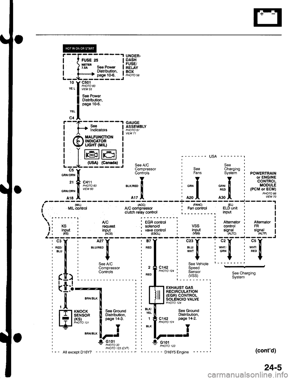
: , See ly'C ' See, See ' Compressor : Charging' Fans : Controls ; System
'YI Y:Y
:l: ll:[
il: l:l
i*"1 i "*"."1 : o"",".o1
, r | : -^*l
ili I i Ii. *, I i rrz.l, ; ot. I'.--..--r-
/i**fffi'* I r,rcffi"oro, i e.St*I ; cornrd ' clulcfi rday ' nput
| .-,---;---l COntrOl
\'
\;t ' Altsrnqtor! Nc Altemator : conrol
/, u.1;lf* roqrsr rnpd FRfrgd ; tSJ",
&rrr:rr
SeeCharornoSystein - :
Y:
!i
u".o I i
i:
o,. .!, iPOWERTRAIN
l*.]["n i 13'"',1+?3.': I MODULE; | (PcM or EcM)
i lw,t?'"
Altornstor ; Iconrol i I
$:--lJ
"''I
',n,-
I
I
See VehicleSpeed Sensorryss)
*[
".,^."
!
I
t
See NCCompressorControls
.r_l
See Charging Sysetm
(cont'd)
23-7
Page 1900 of 2189

i--I,*.;----l
I I ffl* s€€ Pow€' I
!---h=js:q-l
r'1ltii*",
! il"Jiisa"
;ll
i-[*-*"".""--l
! @ffi[+[ffI. !
! Ir6rer i
L--L-,sr@lc5Y
UNDER.DASHFUSE/RELAYBOXPHO|O 58
GAUGEASSEMBLY
;------- USA -------,
see ly'c i S"" :Compressor , See Charging ;Controts , Fans System , POWERTRAIN-
li*t*rr,, ".o^.of, i """f """,tr' i tff'$fit!
Tl,!,
"0o -;;l
i ;;l ^*l i
n"""j.F,rH;
Irs I A17 A :A2oA moA :
,'-----ri;)---7ol------T-;;l----,il--i-----'r,' r',lrr- di-ritror lvc "orip-E""or : Fa; ;;iror eldiinit : II clutci relay conlrcl InPd I\tri---"---i t!9--. i-;ter";--I i{r,*+-i 1s"'*.'lr I t'lc : EGR control : : Atternator I A[emator ]'. I KS : requ6st ; solenoid ; VSS ' control , FR Ia , inDut : inout , \iave control , inpul , sional ' sianal I, , (Ks) i i*"1 , (Esor, _jt,__.j-_JgL-.j__ ,^:_j3------- --- --- -- -.4- -- -- -,1-- - -
i"fiti".,ff:l i"111 iffilifili"F"l
i*l i + i I i
"+
i-"1 :''"1T'See LiC , I ' See vehicle t--'---'-'
ComOressor , 2 ^C142 : SpeedContiofs | | PHoro124 i Sensor
i ft> i :"::l
' ".o
|
",o,o,,0
i lisi: 3i&S**n,"n
i Lti-t i i rh;ry,'s;3+r"" i
: I ""n,".*l iiltll lS'"",.?^8"'$lli'til ""n'"'*! iil-il]J5ff#f."ruuu
i ll.,*'o.* ! *o,o,no i i l'.lT- seecround
: FflSI8$" i Btr"lifiiJ}': i i *i[ Bi,i"EL'""
; f lJffi""' !**;' i i":-lei'u!,7,,"
ws{u'
(cont'd)
24-5
Page 1912 of 2189
@----t UNDER.
I t FUSE 2s I p.4:!
| ) Iff" ses Power | ;"Eiii
I l------+ 3l'i:?'J:" tF,%.,L--*----il--l-J -
'o Y F;%.YELI v/Ew 55
f
--- - - - - - - - - - -;f '-iminats tz'zo1
I c+ lv'rwto
Y r--'1r-:-----'l GAUGE
see Power ! f* l"?i*,".. ! f,s";"ty"ttDisiribution, I , | vtEwTlpass10'6
i @$eFH,t* i
! T16r I
see see !y'c see I I
-ruil |See Startrnq ComDressor Charorno L--V---J----JFans System Conliols Syste-m - C5 y
I I I I
"".11-lro,..
| | | | o"no"n!f[?iSuo
GUN
I
BLUVHT
I
BLKnEo
I
GRNFED
f sVC131
*o I o, .1. o', ,l o.o .l
o"*o*l i[?1o"*
,r---U,a"i---strF-*-*"r"tr8*i-#%,.----;w;,---lneffi [it^'" tan control control ciutch reiay control Input | (pCM) -._ | puoroear AJc Atternaror Atternator l. iir*.i VSS rsquest FR controt I
i '[g3l i"R8!, ",gl,1o "'11'%, IrL------ --------Jc23 ll, l27Y "ur "rX
tlllBtUw}rI
I
BLU,FEo
I
w8r RED I wxr onr I
IIIIYYYY
See Vehicle See A,/C -'-dSpeedSensor Compressor(vss) contiot 3i:,""I"'n'"n
(cont'd)
25-5
I
Page 1948 of 2189
Blower Controls
'96-'98 Models
@
UNDER.HOODFUSE/RELAYBOX
UNDER.DASHFUSE/RELAYBOXPHOTO 5A
BLOWEFnoToRBELAYPEOfO I
HEATER FANSWITCH
6 calrSeeL/cCompressorControls
(
See GroundDbtribution,oaqg 14-5.
See GrorDbtributipage 14.
I
I
_l
ar<
L
- c402
BLU/YEL1l
BLU/
1BLK
BLK
BLK
60
Page 1954 of 2189
A/C Compressor Controls
- AllModels
cc5)M7
BLU/RED
?
\a
@
&cCOMPRESSORCLUTCHRELAYPHOfO 10
a
! ,acc, : POWERTRATN! arn.^-^,o..^, I or ENGINE
! ii i"i-iiii"v i.,ii.r | fi 3$18.
I A/C request ! (pCM or ECM)I (ACSJ a pHOrO a6L------J vtEw 70
REO
BEO
1
RED
BLU/FEO
2
BLU/FEO
ct31
:"1'!i'------;
Fi:rz, a ='e6-'s8: A|| moders except D1685vtEw 21 '99100: D16Y5 with l\illT'* = 96-'98: All models
ir'iio ," 99. 00: Dt6y5 wth t\4/t Dl6Bb
atcPRESSUREswtTcH
c752
c1
".,n""t 1(
".r-".rf, "tA% "
"."-:,fi tfr,]4.
v
To facing page ('96''98 models)or page 62'2 ( 99-'00 models).
-Yl
-t---------Jc353
c2'14
vtEW21
c209
A,/CCOMPRESSORCLUTCH
COMPRESSORTHERMALPROTECTOR
UNDER-HOODFUSE/RELAYBOXf-T-*-'.T'---l H53.',EPA?' i-l-------
i iflH* !F,?r",, i f6F"'.i:.",",
| tsBi":J;"#il ! a T| | oaoe 1o-9. ! I I See PowerL_J1_j:_-_j ! H Distriburion.e Y c42o i I
pase 1o-1.
***
f ifi"l'
^ see power ! |
62
!(on bracket)
Page 1956 of 2189
AiC Compressor Gontrols (cont'd)
- '99-'00 Models
From page 62.
v
I*"-ilii.,"r,
ihtli4
BLUAVHT
15
6LUAVHT
UNDER.HOODFUSE/RELAYBOX
Seg Pow6rDistrlbutiofl,pag€ 'l Gl1-c353PHO|O 8
l[,,*
';.!, "'""
,c,/cSwitch switchcommon itput
a,/cTHERMOSTATOlt below3"C (37"F).
THERMISTOR
(
B11A A8A B'IO |'r--:=---I A/C lgnition B€ttery II request input (backup) :
".j:[ru*,,ry "..;X
{;[
vtEW 57
HEATERCONTROLPANEL
l'lCswitch SwitchLgD IEDcodrol cormonGrouod
See AirD€livery,RgarWindowD€foggar
BIK
cl
ORN
c5
GBN
r,/cOt'llndicatof
HEATERPUSHswrTcHEs
t/cSwltch
S€e AirDelivefy,RearWindowDslogg6f
See GroundDist.ibdion,page 1,1-5.
Y
I(
=ffi;
(
.I UNDER.
I HOODi FUSE/I RELAYI Box
IJ
62-2
PHOfO 125
Page 1957 of 2189

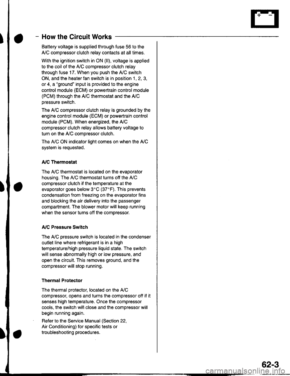
- How the Circuit Works
Battery voltage is supplied through tuse 56 to the
A,/C compressor clutch r€lay contacts at all times.
With the ignition switch in ON (ll), vollage is applied
to the coil of the A,/C compressor clutch relay
through fuse 17. When you push the A,/C switch
ON, and the heater fan switch is in position | , 2, 3,
or 4, a "ground" input is provided to the engine
control module (ECM) or powertrain control module
(PCM) through the l'lC thermostat and the l'lC
pressure switch.
The A,/C compressor clutch relay is grounded by the
engine control module (ECM) or powertrain control
module (PCM). When energized, the A'lC
compressor clutch relay allows battery voltage to
turn on the A,/C comDressor clutch.
The A,/C ON indicator light comes on when the A,/C
system is requested.
A,/C Thermostat
The A'lC thermostat is located on the evaoorator
housing. The A,/C thermostat turns off the A,/C
compressor clutch if the temperature at the
evaporator goes below 3'C (37'F). This prevents
condensation from freezing on the evaporator fins
and blocking the air delivery into the passenger
compartment. The blower motor will keep running
when the sensor turns off the comDressor.
A,/C Pressure Switch
The fuC oressure switch is located in the condenser
outlet line where refrigerant is in a high
temperature/high pressure liquid state. The switch
will sense abnormally high or low pressure, and
open the circuit. This removes ground, and the
compressor will stop running.
Thermal Protectot
The thermal protector, located on the A,/C
compressor, opens and turns the compressor off if it
senses high temperature. Once the compressor
cools, the switch will close and the compressor will
begin running again.
Refer to the Service Manual (Section 22,
Air Conditioning) for specific tests or
troubleshooting procedures.
62-3
Page 1961 of 2189

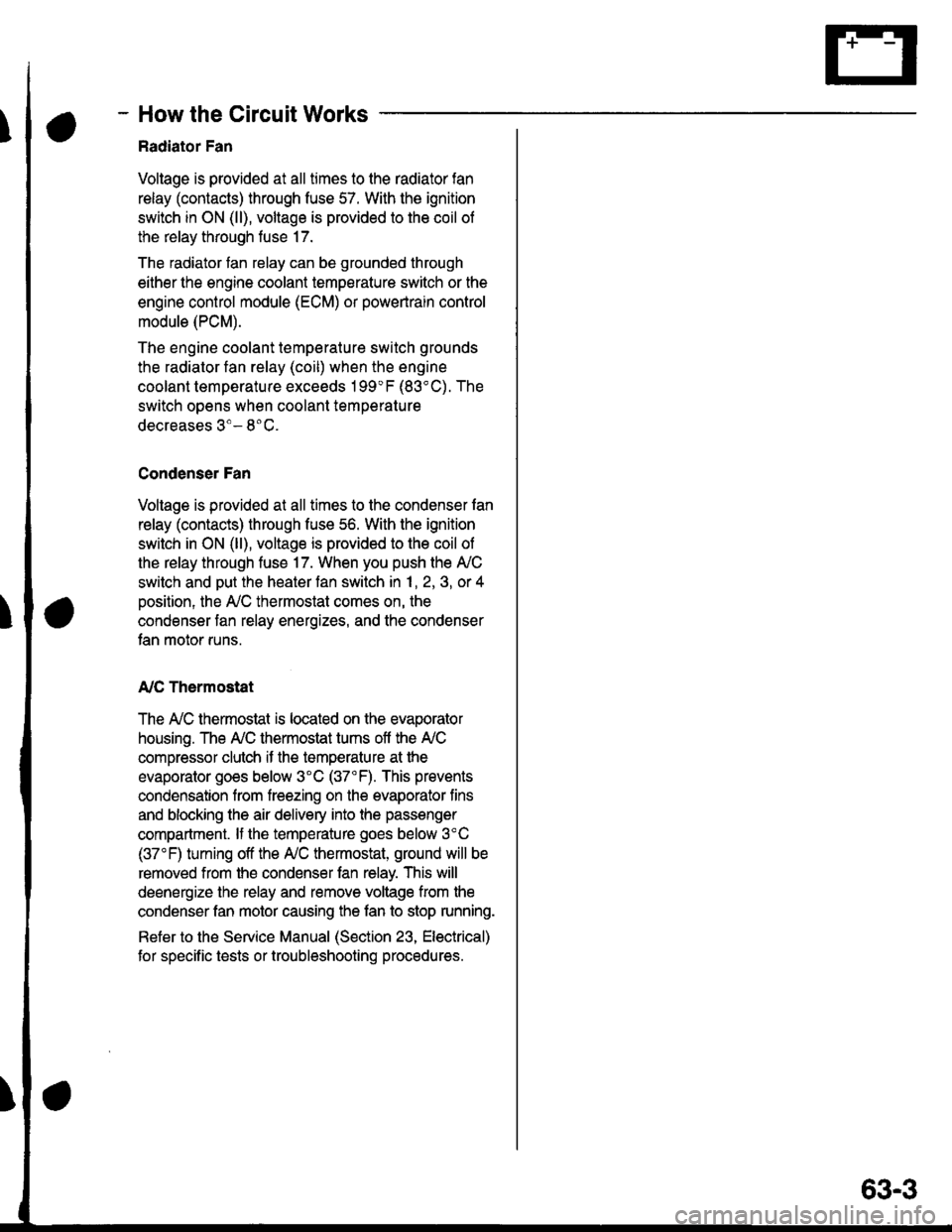
- How the Circuit Works
Radiator Fan
Voltage is provided at all times to the radiator fan
relay (contacts) through fuse 57. With the ignition
swilch in ON (ll), voltage is provided to the coil of
the relay through luse 17.
The radiator tan relay can be grounded through
either the engine coolant temperature switch or the
engine control module (ECM) or powertrain control
module (PCM).
The engine coolant temperature switch grounds
the radiator fan relay (coil) when the engine
coolant temperature exceeds 199'F (83'C). The
switch opens when coolanl temperature
decreases 3'- 8'C.
Condenser Fan
Voltage is provided at all times to the condenser fan
relay (contacts) through fuse 56. With the ignition
switch in ON (ll), voltage is provided to the coil of
the relay through fuse 17. When you push the A'lC
switch and put the heater fan switch in 1, 2,3, o( 4
position, the ly'C thermostat comes on, the
condenser fan relay energizes, and the condenser
fan motor runs.
A,/C Thermostat
The A,/C thermostat is located on the evaporator
housing. The A,/C thermostat tums off the A/C
compressor clutch if the temperature at the
evaporator goes below 3'C (37'F). This prevents
condensation from freezing on the evaporator fins
and blocking the air delivery into the passenger
compartment. lf the temperature goes below 3'C
(37"F) tuming off the Ay'C thermostat, ground will be
removed from the condenser fan relay. This will
deenergize the relay and remove voltage from the
condenser fan motor causing the fan to stop running.
Reter to the Service Manual (Section 23, Eleckical)
for specific tests or troubleshooting procedures.
63-3