Page 975 of 2189

Stall Speed
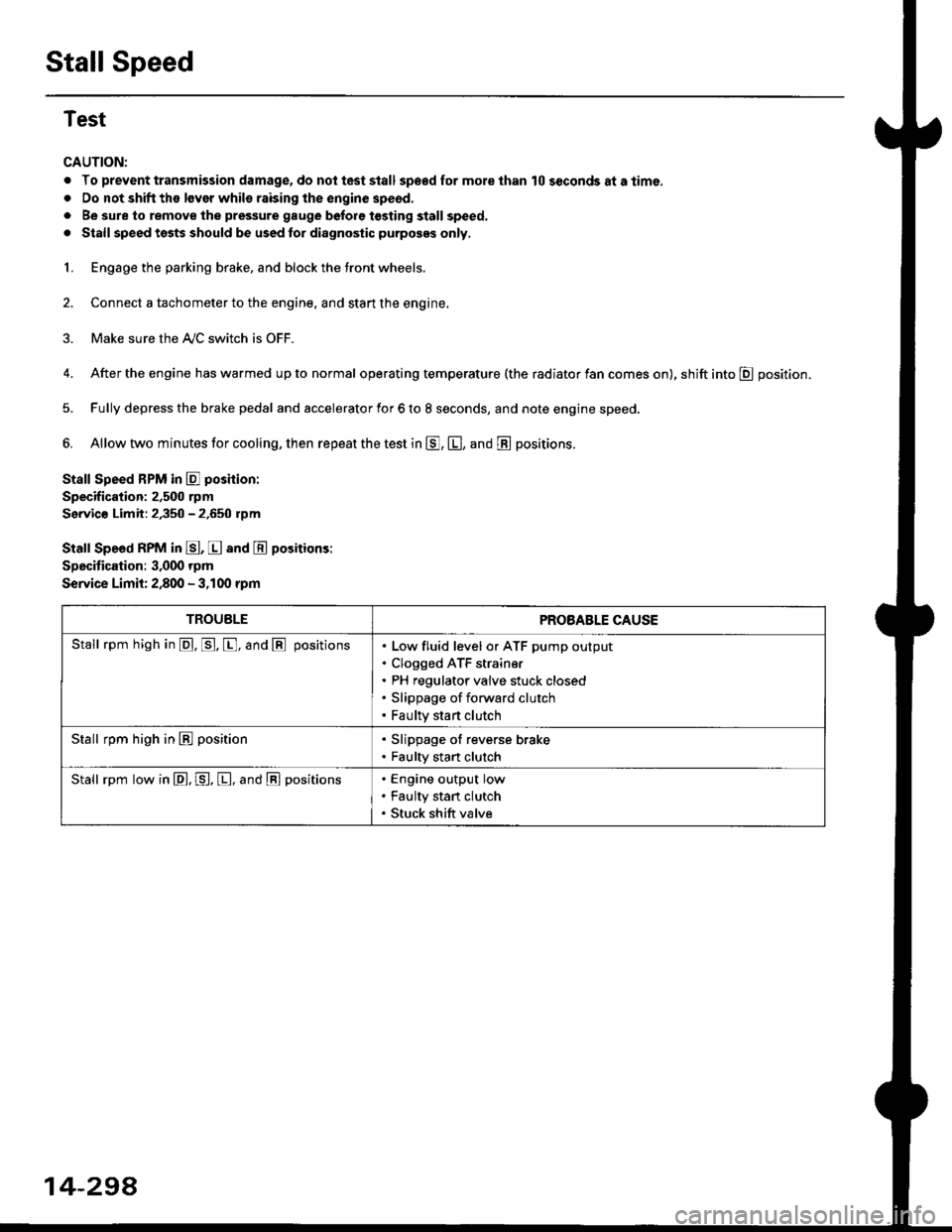
Test
CAUTION:
. To prevent transmission damage, do not test stall sp€€d for mole than 10 seconds at a time.
. Do not shift the lsver whils raising the engine speod.
. Be sure lo remove the pressure gauge before tosting stall speed.
. Stall speed tssts should be used tor diagnostic purposes only,
1. Engage the parking brake, and block the tront wheels.
2. Connect a tachometer to the engine, and stan the engine.
3. Make sure the A/C switch is OFF.
4. After the engine has warmed up to normal operating temperature (the radiator fan comes on), shift into E position.
5. Fully depress the brake pedal and accelerator for 6 to 8 seconds, and note engine speed,
6. Allow two minutes for cooling, then repeat the test in E, E, and E positions.
Stall Speed BPM in E poshion:
Specification: 2,500 rpm
Servic€ Limit: 2,350 - 2.650 rpm
Stall Speed RPM in E, E and E positions:
Specitication: 3,000 rpm
Service Limit: 2,800 - 3,100 rpm
TROUBLEPROBABLE CAUSE
Stall rpm high in @. p. [, and @ positionsLow fluid level or ATF pump output
Clogged ATF strain€r
PH regulator valve stuck closed
Slippage of forward clutch
Faulty start clutch
Stall rpm high in E position. Slippage of reverse brake. Faulty start clutch
Stall rpm low in E, P, [, and @ positionsEngine output low
Faulty stan clutch
Stuck shift valve
14-294
Page 976 of 2189

Fluid Level
l.Checking/Changing
CAUTION: while chscking and changing, be sure not to
allow dust and other toreign particles to ent€l inlo the
transmission.
Checking
NOTE: Check the fluid level with the engine at normal
operating temperature (the radiator fan comes on).
'1. Park the vehicle on the level ground. Turn oft the
engrne.
2. Remove the dipstick (yellow loop) from the trans-
mission, and wipe lt with a clean cloth.
NOTE: Check the transmission fluid 50 to 90 sec-
onds after shutting off the engine.
3. Insert the diDstick into the transmission.
DIPSTICK (YELLOW LOOPI
Remove the dipstick and check the fluid level.
should be between the uDDer and lower mark.DIPSTICK
5. lf the level is below the lower mark, add fluid into
the filler hole to bring it to the upper mark. Use
Genuine Honda CW Fluid only.
6. Insert the dipstick into the transmission.
14-299
Changing
1. Bring the transmission up to normal operating tem-
perature (the radiator fan comes on) by driving the
vehicle. Park the vehicle on the level ground, and
turn off the engine.
2. Bemove the drain plug, and drain the CVT fluid.
NOTE| lf a cooler flusher is to be used, see page 14-
352 and 14-353.
Reinstall the drain plug with a new sealing washer,
then refill the transmission with Genuine Honda
CVT Fluid to the upper mark on the dipstick.
Automatic Transmission Fluid CaPacity:
3.9 i (4.r US qt. 3.4 lmp qt) 8t chlnging
6.4 I (6.8 US qt, 5.6 lmp qt) 8t ov€lhaul
Rscommended Automatic Transmission Fluid:
Genuine Honda CVT Fluid-
Use Genuine Honda CW fluid only. Using other flu-
ids can affect transmission operation and may
reduce transmission liJe.
Change Interval:
Normal Condition: 30, 000 miles 148,000 km)
Severe Condition: 30,000 miles (48,000 km), but it
you drive at high sPeeds in high
t90"F (32'C) and abovol temper-
atures, the ttansmission fluid
should be changed evsrY 15,000
miles 124,000 km).
{-]lr
ORAIN PLUG18 x 1.5 mma9 N.7n (5.0 kgl.m, 36 lb{'ftl
SEALING WASHERReplace.
Page 977 of 2189

Pressure Testing
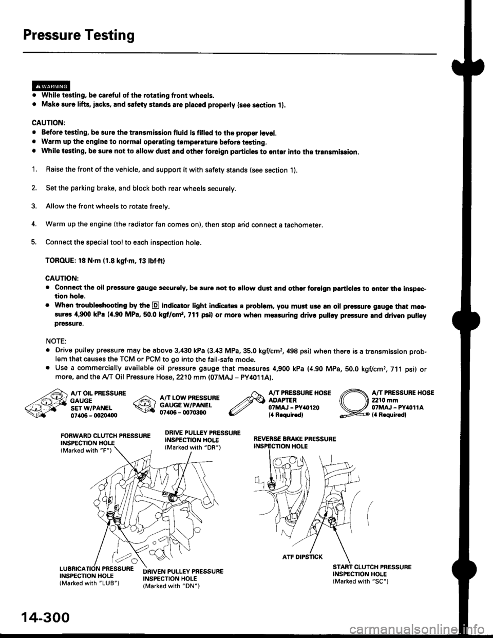
. While testing, be careful of the rot8ling front wheels.
. M8k6 suro lifts, iacks, and satety stands are placed properly lsee section 11.
CAUTION:
. Before testing, be sur. the transmb3ion fluid is fillod to the propor lcvel.. Warm up the engin€ to nolmal operating tsmperature bofore testing. While t€sting, be 3ure not to allow dust and other loreign particles to onler into the transmi$ion.
1. Raise the front of the vehicle, and support it with safety stands (see section 1).
2. Set the parking brake. and block both rear wheels securely.
3. Allow the front wheels to rotate freely.
4. Warm up the engine (the radiator fan comes on), then stop arid connect a tachometer.
5. Connect the special tool to each inspection hole.
TOROUE: 18 N.m (1.8 kgt'm, 13 tbtfr)
GAUTION:
. Connect the oil pressuro gauge !!€curoly, bs sur6 not to allow dust and other foroign particlG3 to ontar the inspsc-tion hole.
. Whon troubleshooting by tho E indicltor light indic.t6 a problam. you mu3t u3e an oil p.essure gluge that moa,sures 4,9(X) kPa (a.90 MPa,50.0 kS cr*,771psi) or more when molsuring driv. pulley pressure and driven pullcypre33ure.
NOTE:
. D.ive pulley pressure may be above 3,430 kPa (3.i8 MPa,35.0 kgf/cmr, 498 psi) wh€n there is a transmission prob-
lem that causes the TCM or PCM to go into the fail-safe mode,. Use a commercially available oil pressure gauge that measures 4,900 kPa {4.90 MPa, 5O.O kgf/cmr, 711 psi) ormore, and the Ay'T Oil Pressure Hose, 2210 mm (07MAJ - PY4011A).
FORWARD CLUTCH PRESSUREINSPECTION
lMarked with "F")
REVERSE BRAKE PRESSUREINSPECTION I.IOLE
A/T OIL PRESSUREGAUGESET W/PANEL0ta{r6 - oO2Oi|(Xt
A/T LOW PRESSUREGAUGE W/PANEL0706 - qt7o:t{ro
DRIVE PULLEY PRESSUREINSPECTION HOI.E(Marked with "DR")
A/T PRESSURE HOSEADAPTER07MAJ - PYar'120lil R.qulr.d)
A/T PRESSUBE HOSE2210 mm07MAJ - PYitollAla R.quir.d)
(
INSPECNON HOLE(Marked with "SC")
CLUICH PRESSURE
INSPECTION HOLE(Marked with "LUB")
DRIVEN PULLEY PRESSUREINSPECTION HOLElMarked with "DN")
14-300
ATF DIPSTICK
Page 978 of 2189

1.
Start the engine.
Shift to the respective shift lever positions in the table, and measure the following pressures at 1'500 rpm'
. Forward Clutch Pressure
. Reverse Brake Pressure
. Drive Pulley Pressure
. Driven Pulley Pressure
8. Shift to E posltion, and measure the lubrication pressure at 3,000 rpm'
Disconnect the special tool after pressure testlng
Install the sealing boits in the jnspection holes with new sealing washers, and tighten the bolts to the specified
toroue.
TOROUE: 18 N.m {1.8 kgf'm, 13 lbf'ft}
CAUTION: Keep all foreign particles out of the transmission'
9.
10.
PBESSURESHIFT LEVER
POSmONSYMP{OMPROBABLE CAUSE
FLUID PRESSURE
Standard/Ssrvice Limit
Forwa rd
Clutch
ENo or low for-
ward clutch
pressure
Forward Clutch1.4 - 1.75 MPa
(14.3 - 17.8 kgtcm'�, 203 - 253 Psi)
Reverse
Brake
tsNo or low
reverse brake
pressure
Reverse Brake1.4 - 1.75 MPa
(14.3 - '17.8 kg7cm'�, 203 - 253 Psi)
Drive
Pulley
NNo or low
drive pulley
pressure
ATF pump, PH reg-
ulator valve, PL
regulator valve,
Shift valve
0.2 - 0.7 MPa
(2 - 7.1 kgflcm'�, 28 - 101 Psi)
Drive pulley
pressure roo
high
PH regulator valve,
PL regulator valve,
Shift valve. Shift
control linear
solenoid
Driven
Pulley
No or low
driven pulley
pressure
ATF pump, PH reg-
ulator valve, Shift
valve, Shift control
linear solenoid
1.5 - 2.3 MPa
(15.3 - 23.5 kg?cm'�, 218 - 334 Psi)
Driven pulley
pressure too
h igh
PH regulator valve
LubricationNo or low
lubrication
pressure
ATF pump,
Lubrication valve
Above 0.2 MPa
(Above 2 kgf/cm'�. 30 Psi)
14-301
Page 981 of 2189

Transmission
Removal
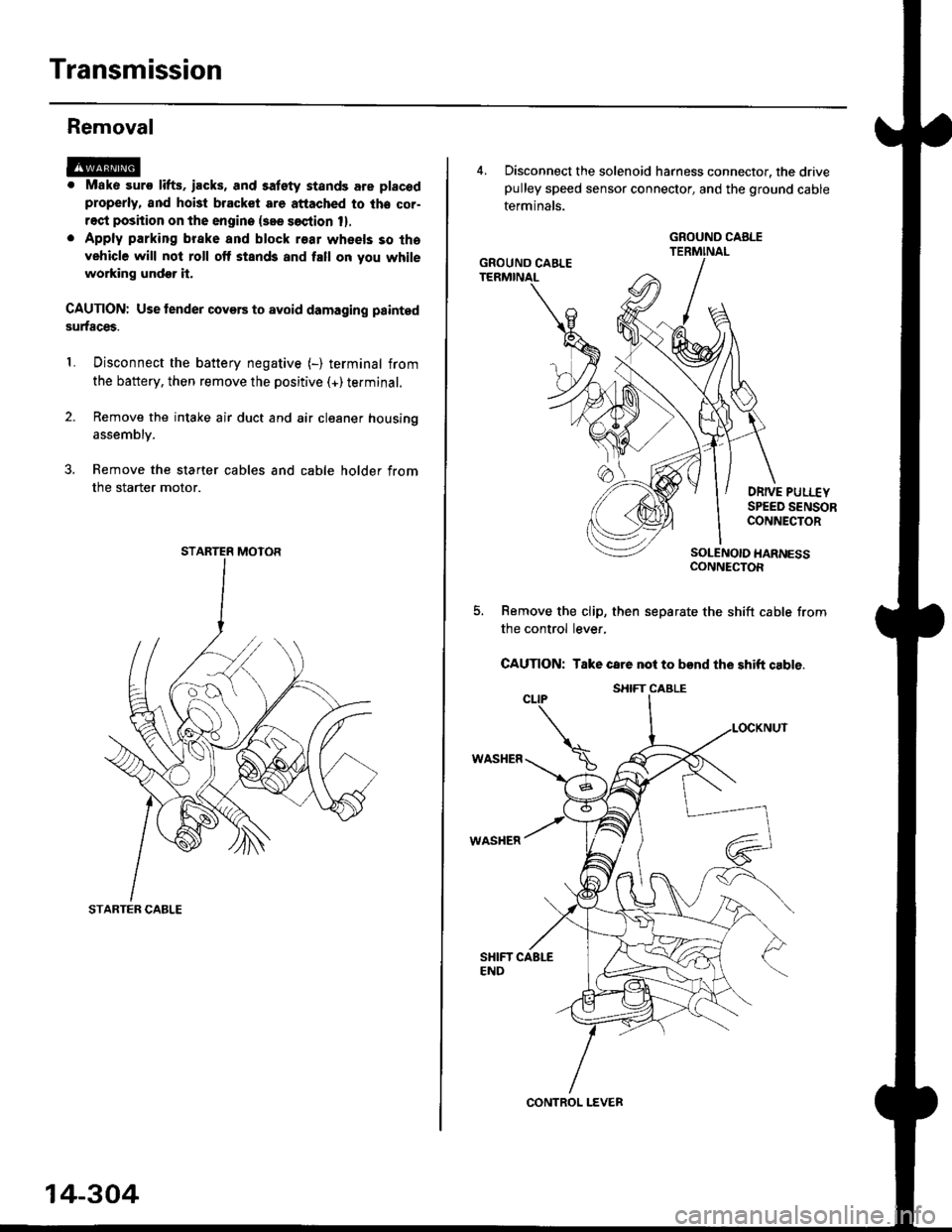
@. Mako suro lifts. iacks, and satety stands are placod
properly, and hoi3t bracket are attached to lhe cor-
rect position on the engine {see soction 1}.
. Apply parking brake and block r€ar wheels so tha
vehicle will not roll off stands and fall on you while
working undor it.
CAUTION: Use tender covers to avoid damaging painted
surfaces.
Disconnect the battery negative (-) terminal from
the battery, then remove the positive (+)terminal.
Remove the intake air duct and air cleaner housing
1.
assembly.
3. Remove the starter cables and cable holder from
the starter motor.
STARTER CABLE
STARTER MOTOR
14-304
4, Disconnect the solenoid harness connector, the drivepulley speed sensor connector, and the ground cable
terminals.
DRIVE PULI.-EYSPEED SENSORCONNECTOR
SOLENOIO HARNESSCONNECTOR
Remove the clip, then separate the shift cable from
the control lever,
CAUTION: Take care not to bend the shift cable.
WASHER
WASHER
GROUND CABLE
GROUND CAELE
CONTROL LEVER
S}IIFT CABLE
Page 983 of 2189

Transmission
Removal (cont'd)
10. Remove the cotte. pins and castle nuts, then separatethe ball joints from the lower arm (see section 1g).
SELF-LOCKING -=V,
NUT \Replace. oitupea rOax
Remove the right damper fork bolt, then separateright damper fork and damper.
Pry the right and left driveshafts out of the differen-tial.
Pull on the inboard joint to remove the right and leftdriveshafts (see section 16).
Tie plastic bags over the driveshaft ends.
NOTE: Coat all precision finished surfaces with cleanengine oil.
Remove the exhaust pipe A.
/\<,\CASTLE I{UT COTTERReplac6.
't 1.
't2.
tJ.
14.
q.
SELF.LOCKINGNUTReplace.
SELF.LOCKING NUTReplace.
14-306
EXHAUST PIPE A
19.
'16, Remove the right front mounvbracket,
ATF COOLER HOSE
17. Remove the ATF cooler hoses at the ATF coolerlines. Turn the ends of the ATF cooler hoses uo toprevent CVT fluid from flowing out, then plug theATF cooler hoses and lines,
NOTE: Check for any sign of leakage at the hosejoints.
18. Remove the engine stiffeners and the flywheel cover.
Remove the eight drive plate bolts one at time whilerotating the crankshaft pullev.
ENGINE STIFFENER
Page 984 of 2189
Remove the distributor'
Atach a hoisting bracket to the engine, then lift the
engine slightly.
Place a iack under the transmission. and raise the
transmission just enough to take weight off of the
mounts, then remove the transmission mount bracket
TRANSMISSION MOUNT
22.
TRANSMISSION MOUNT
14-307
23. Remove the transmission housing mounting bolt
and rear engine mounting bolts
REAR ENGINE MOUNTING
TRANSMISSION HOUSING
MOUNTING BOLT
Pull the transmission away from the engine until it
clears the l4 mm dowel pins, then lower it on the
transmission jack
WASI{ER
Page 1024 of 2189

Transmission
Installation
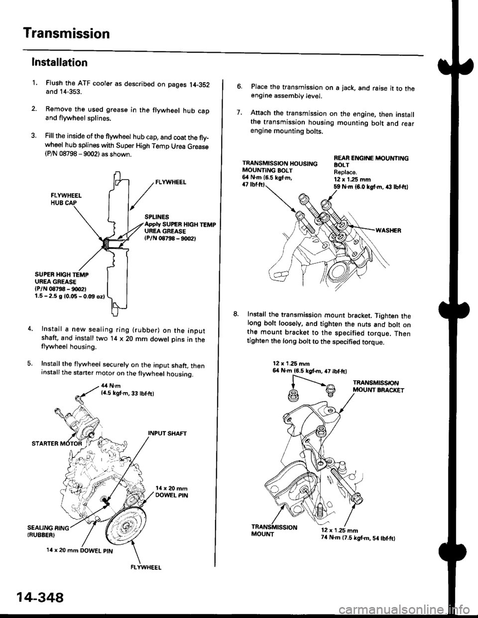
Flush the ATF cooler as described on pages 14-352and 14-353.
Remove the used grease in the flywheel hub caDand flywheel splines.
Fill the inside of the flywheel hub cap, and coat the fly-wheel hub splines with Super High Temp Urea Grease(P/N 08798 - 9002) as shown.
L
SEALING RING{RUEBER)
SPLINESApply SUPEB HlcH TEMPUREA GREASElPlN 08798 - 90O2t
SUPER HIGH TEMPUREA GREASE(P/N 08798 - !)00211.5-2.5 g 10.05-0.t9 oz)
Install a new sealing ring (rubber) on the inoutshaft, and install two '14 x 20 mm dowel Dins in theflywheel housing.
Install the flywheel securely on the input shaft, theninstallthe starter motor on the flywheel housing.
4,1Nmla.5 kgt.m, 33 tbt.ft)
INPUT SHAFT
STARTER
l4 x 20 mm DOWEL ptN
.4;i "lrj
,i rr,"r., ., a
14-348
FLYWHEEL
MOUI{T74 N.m (7.5 tstm,5a tbtftt
6. Place the transmission on s jack, and raise it to theengine assembly level.
7. Anach the transmission on the engine, then installthe transmission housing mounting bolt and rearengine mounting bolts.
TRANSMISSION HOUSINGMOUNTING BOIT6,1 N.m 16.5 kgl.m,47 tbtttl59 Nrn {6.0 kgl.m. ,€ lbt ftl
WASHER
lnstall the transmission mount bracket. Tighten thelong bolt loosely, and tighten the nuts and bott onthe mount bracket to the specified torque. Thentighten the long bolt to the specified torque.
REAR ENGINE MOUNTINGBOLTReplace.12 x 1.25 mm
12x 1.25 mn6,r N'm 16.5 kgtm,47 tbtftl
l-".--..-,^
G\V
TRANSMISSONMOUNT BRACKET
12 x 1.25 mn