1999 HONDA CIVIC Engine
[x] Cancel search: EnginePage 868 of 2189

Shift Cable
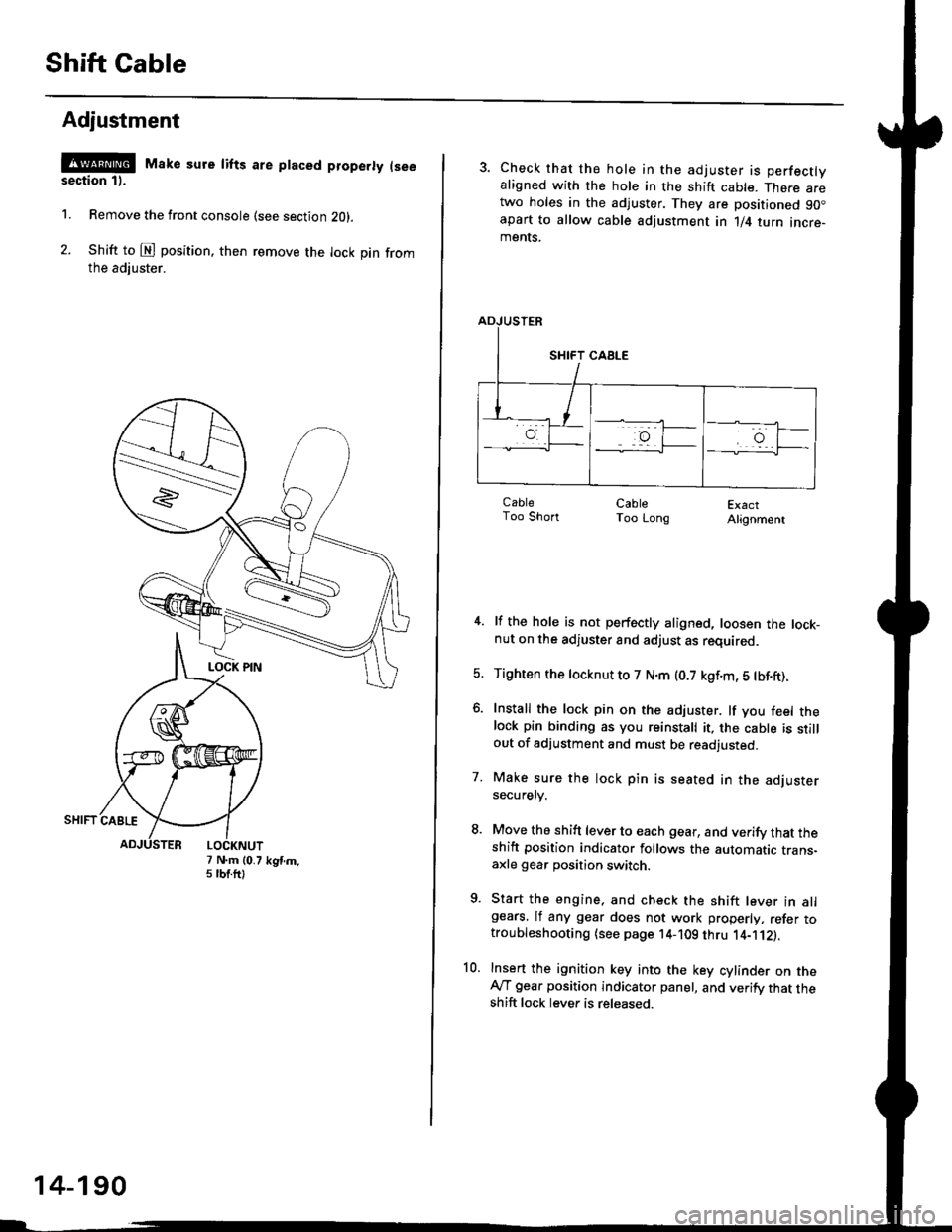
Adjustment
@ Make sure lifts are ptaced properly (see
section 1).
1. Remove the front console (see section Z0l.
2. Shift to @ position. then remove the lock pin fromthe adiuster.
7 N.m (0.75 tbtftlkgtm.
14-190
3. Check that the hole in the adjuster is perfectlyaligned with the hole in the shift cable. There aretwo holes in the adjuster. They are positioned 90.apart to allow cable adjustment in 1/4 turn incre-ments.
ExactAlignment
4. lf the hole is not perfectly aligned, loosen the lock-nut on the adjuster and adjust as required.
5. Tighten the tocknut to 7 N.m (0.7 kgf.m, 5 tbf.ft).
6. Install the lock pin on the adjuster. lf you feel thelock pin binding as you reinstall it, the cable is stillout of adjustment and must be readjusted.
7. Make sure the lock pin is seated in the adjustersecuretv.
8. Move the shift lever to each gear, and verify that theshift position indicator follows the automatic trans-axle gear position switch.
9. Start the engine, and check the shift lever in allgears. lf any gear does not work properly, refer totroubleshooting (see page 14-109 thru 1'4-'112).
10. Insert the ignition key into the key cylinder on theAy'T gear position indicator panel, and verify that theshift lock lever is released.
CableToo ShortCableToo Long
Page 873 of 2189

Description
The Continuously Variable Transmission (CVT) is an electronically controlled automatic transmission with drive and driv
en Oullevs, and a steel belt. The CVT provides non stage speeds forward and one reverse. The entire unit is positioned in
line with the engine.
Transmission
Around the outside of the flywheel is a ring gear which meshes with the starter pinion when the engine is being staned.
The transmission has four parallel shafts: the input shaft, the drive pulley shaft. the driven pulley shaft, and the secondary
gear shaft. The input shaft is in line with the engine crankshaft. The drive pulley shaft and the driven pulley shaft consist of
movable and fixed face pulleys. Both pulleys are linked by the steel belt.
The input shaft includes the sun gear. The drive pulley shaft includes the forward clutch which mounts the carrier assem-
bly on the forward clutch drum. The carrier assembly includes the pinion gears which mesh with the sun gear and the ring
gear. The ring gear has a hub-mounted reverse brake disc.
The driven pulley shaft includes the start clutch and the secondary drive gear which is integral with the park gear' The sec-
ondary gear shaft is positioned between the secondary drive gear and the final driven gear. The secondary gear shaft
includes the secondary driven gear which serves to change the rotation direction. because the drive pulley shaft and the
driven oullev shaft rotate the same direction. When certain combinations of planetary gears in the transmission are
engaged by the clutches and the reverse brake, power is transmitted from the drive pulley shaft to the driven pulley shaft
to provide E, E, E, and El.
Electronic Control'96 - 98 Models:
The electronic control system consists of the Transmission Control Module (TCM), sensors, three linear solenoids, and a
inhibitor solenoid. Shifting is electronically controlled under all conditions'
The TCM is located below the dashboard, behind the kick panel on the driver's side.'99 - 00 Models:
The electronic control svstem consists of a Powertrain Control Module (PCM), sensors, three linear solenoids and an
inhibitor solenoid. Shifting is electronically controlled under all conditions. A Grade Logic Control System to control shift-
ing in E position while the vehicle is ascending or descending a slope.
The PCM is located below the dashboard, under the kick panel on the passenger's side.
Hydraulic Control
The lower valve body assembly includes the main valve body, the Pressure Low (PL) reguiator valve body, the shift valve
body, the start clutch control valve body, and the secondary valve body. They are positioned on the lower part of the
transmission housing.
The main valve body contains the Pressure High (PH) control valve, the lubrication valve, and the pitot regulator valve.
The secondary valve body contains the PH regulator valve, the clutch reducing valve, the start clutch valve accumulator,
and the shift inhibitor valve. The PL regulator valve body contains the PL regulator valve and the PH-PL control valve
which is ioined to the PH,PL control linear solenoid. The inhibitor solenoid valve is bolted on the PL regulator valve body.
The shift valve body contains the shift valve and the shift control valve. which is joined to the shift control linear solenoid.
The start clutch control valve body contains the start clutch control valve, which is joined to the start clutch control linear
solenoid. The linear solenoids and the inhibitor solenoid are controlled by the TCM or PCM. The manual valve body which
contains the manual valve and the reverse inhibitor valve, is bolted on the intermediate housing.
The ATF pump assembly is located on the transmission housing, and is linked with the input shaft by the sprockets and
the sprocket chain. The pulleys and the clutch receive fluid from their respective feed pipes, and the reverse brake receives
fluid from internal hydraulic circuit.
Shift Control Mechanism
Input from various sensors located throughout the vehicle determines which linear solenoid the TCM or PCM will activate.
Activating the shift control linear solenoid changes the shift control valve pressure, causing the shift valve to move. This
pressurizes the drive pulley pressure to the drive pulley and the driven pulley pressure to the driven pulley and changes
their effective pulley ratio. Activating the start clutch control linear solenoid moves the start clutch control valve. The start
clutch control valve uncovers the port, providing pressure to the start clutch to engage it(cont'd)
14-195
,!
Page 874 of 2189

Description
(cont'd)
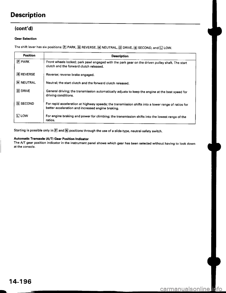
Gear Sel€stion
The shift lever has six positions: @ pARK, E REVERSE, E NEUTRAL, E DR|VE, g SECOND, and El LOW.
Staning is possible only in E and E positions through the use of a slid6-type, neutrafsafety switch.
Automrtic Transaxle {A/T} Gear Position Indicltor
The A-lT gear position indicator in the instrument panel shows which gear has been selected without having to look downat the console.
PoshionDe3cription
E PARK
E REVEBSE
E NEUTRAL
D DRIVE
E SECOND
E LOW
Front wheels locked; park pawl engaged with the park gear on the driven pulley shaft. The startclutch and the forward clutch released.
Reverse; reverse brake engaged.
Neutral; the start clutch and the forward clutch released.
General driving; the transmission automatically adjusts to keep the engine at the best speed fordriving conditions.
For rapid accelsration at highway speeds; the transmission shifts into a lower range of ratios forbetter acceleration and increased engine braking.
For engine braking and power for climbinO; the transmission shifts into the lowest range of theralros.
l-
14-196
Page 876 of 2189

Description
Clutches/Reverse Brake/Planetary Gear/Pulleys
Clulches/Reverse Brake
The CVT uses the hydraulically-actuated clutches and brake to engage or disengage the transmission gears. When
hydraulic pressure is introduced into the clutch drum and the reverse brake piston cavity, the clutch piston and the reverse
brake piston move. This presses the friction djscs and the steel plates together, locking them so they don't slip. Power is
then transmitted through the engaged clutch pack to its hub-mounted gear. and through engaged ring gear to pinion
gears.
Likewise, when the hydraulic pressure is bled from the clutch pack and the reverse brake piston cavity, the piston releases
the friction discs and the steel plates, and they are free to slide past each. This allows the gear to spin independently on its
shaft, transmitting no power.
Start Clutch
The start clutch, which is located at the end of the driven pulley shaft, engages/disengages the secondary drive gear.
The start clutch is supplied hydraulic pressure by its ATF feed pipes within the driven pulley shaft.
Forward Clutch
The forward clutch, which is located at the end of the drive pulley shaft, engages/disengages the sun gear.
The forward clutch is supplied hydraulic pressure by its ATF feed pipe within the drive pulley shaft.
Reverse Brake
The reverse brake, which is located inside the inte.mediate housing around the ring gear, locks the ring gear in E posi-
tion. The reverse brake discs are mounted to the ring gear and the reverse brake plates are mounted to the intermediate
housing. The reverse brake is supplied hydraulic pressure by a circuit connected to the internal hydraulic circuit.
Planetary Gear
The planetary gear consists of a sun gear, a carrier assembly, and a ring gear. The sun gear is connected to the input shaft
with splines. The pinion gears are mounted to the carrier which is mounted to the fo.ward clutch drum. The sun gear
inputs the engine power via the input shaft to the planetary gear, and the carrier outputs the engine power. The ring gear
is only used for switching the rotation direction of the pullev shafts,
In E. E, and E positions (forward range), the pinion gears don't rotate and revolve with the sun gear, so the carrier
rotates. In E] positjon {reverse range), the reverse brake locks the ring gear and the sun gear drives the pinion gears to
rotate. The pinion gears rotate and revolve in the opposite direction from the rotation direction of the sun gear, and the
carrier rotates with pinion gear revolution.
Pulleys
Each pulley consists of a movable face and a fixed face, and the effective pulley .atio changes with engine speed. The
drive pulley and the driven pulley are linked by the steel belt.
To achieve a low pulley ratio, high hydraulic pressure works on the movable face of the driven pulley and reduces the
effective diameter of the drive pulley. and a lower hydraulic pressure works on the movable face of the drive pulley to
eliminate the steel belt slippage. To achieve a high pulley ratio, high hydraulic pressure works on the movable face of the
drive pulley and reduces the eifective diameter of the driven pulley, and a lower hydraulic pressure works on the movable
face of the driven pulley to eliminate the steel belt slippage.
b
14-198
Page 881 of 2189

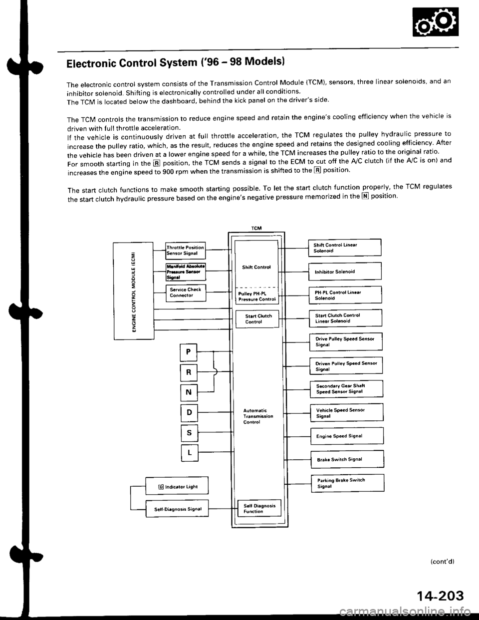
Electronic Control System ('96 - 98 Modelsl
The electronic control system consists of the Transmission control Module (TcM), sensors, three linear solenoids, and an
inhibitor solenoid. Shifting is electronically controlled under all conditions
The TCIM is located below the dashboard, behind the kick panel on the driver's side'
The TcN4 controls the transmission to reduce engine speed and retain the engine's cooling efficiency when the vehicle is
driven with Iull throttle acceleration
lf the vehicle is continuously driven at full throttle acceleration, the TCM regulates the pulley hydraulic pressure to
increase the pulley ratio, which, as the result. reduces the engine speed and retains the designed cooling efficiency After
the vehicle has been driven at a lower engine speed for a while, the TCM increases the pulley ratio to the original ratio.
For smooth starting in the E position, the TcM sends a signal to the EcM to cut off the rvc clutch {if the A!/c is on) and
increases the engine speed to 900 rpm when the transmission is shifted to the E position'
The start clutch functions to make smooth starting possible. To let the start clutch function properly. the TCM regulates
the start clutch hydraulic pressure based on the entine's negative pressure memorized in the E position'
:
:
z
z
z
S*ond.ry G..r Sh:ft
(cont'd)
14-203
Page 883 of 2189

Electronic Gontrol System ('99 - 00 Modelsl
The electronic controt system conststs of a Powertrain control Module (PCM). sensors, three linear solenoids and an
inhibitor solenoid. shifting is electronically controlled under all conditions A Grade Logic control system to control shift-
ing in E position while the vehicle is ascending or descending a slope'
fn"pCVirlocatedbelowthedashboard,underthekickpanelonthepassenger'sside'
The pCM controls the transmassion to reduce engine speed and retain the engine's cooling efficiency when the vehicle is
driven with full throftle acceleration
lf the vehicle is continuously driven at lull throttle acceleration, the PCM regulates the pulley hydraulic pressure to
increase the pulley ratio which. as the result, reduces the engine speed and retains the designed cooling efficiency After
the vehicle has been driven at a lower engine speed for a while, the PCM increases the pulley ratio to the original ratio'
i"i ".nl",rr starting in the E position, the PcM cuts off the ,Vc clutch (if the A/c is on) and increases the engine speed to
900 rpm when the transmission is shifted to the E position'
The start clutch functions to make smooth starting possible. To let the start clutch function properly, the PcM regulates
the start clutch hydraulic pressure based on the engine's negative pressure memorized in the E position'
FCM
s*o.d.ry G..t Sh.h
(cont'd)
14-205
Page 884 of 2189

Description
Electronic Control System ('99 - 00 Modelsl (cont'dl
Grade Logic Control System
How it works:
The PcM compares actual driving conditions with memorized driving conditions. based on the input from the vehiclespeed sensor, the throttle position sensor, the manifold absolute pressure sensor, the engine coolant temperature sensor,the brake switch signal, and the shift lever position signal, to control shifting while the vehicle is ascending or descendinga slope.
Ascending Control
When the PCM determines that the vehicle is climbing a hill in E position, the system selects the most suitable shiftschedule (pulley ratio) according to the magnitude of a gradient. so the vehicle can run smooth and have more powerwhen needed. There are three ascending modes with different shift schedules according to the magnitude ot a gradient inthe PCM.
Descending Control
when the PCM determines that the vehicle is going down a hill in E position. the system selects the most suitable shiftschedule (pulley ratio) according to the magnitude of a gradient. This, in combinstion with engine braking, achievessmooth driving when the vehicle is descending, There are three descending modes with different shift schedules accord-ing to the magnitude of a gradient in the PCM.
L
14-206
Page 886 of 2189

Description
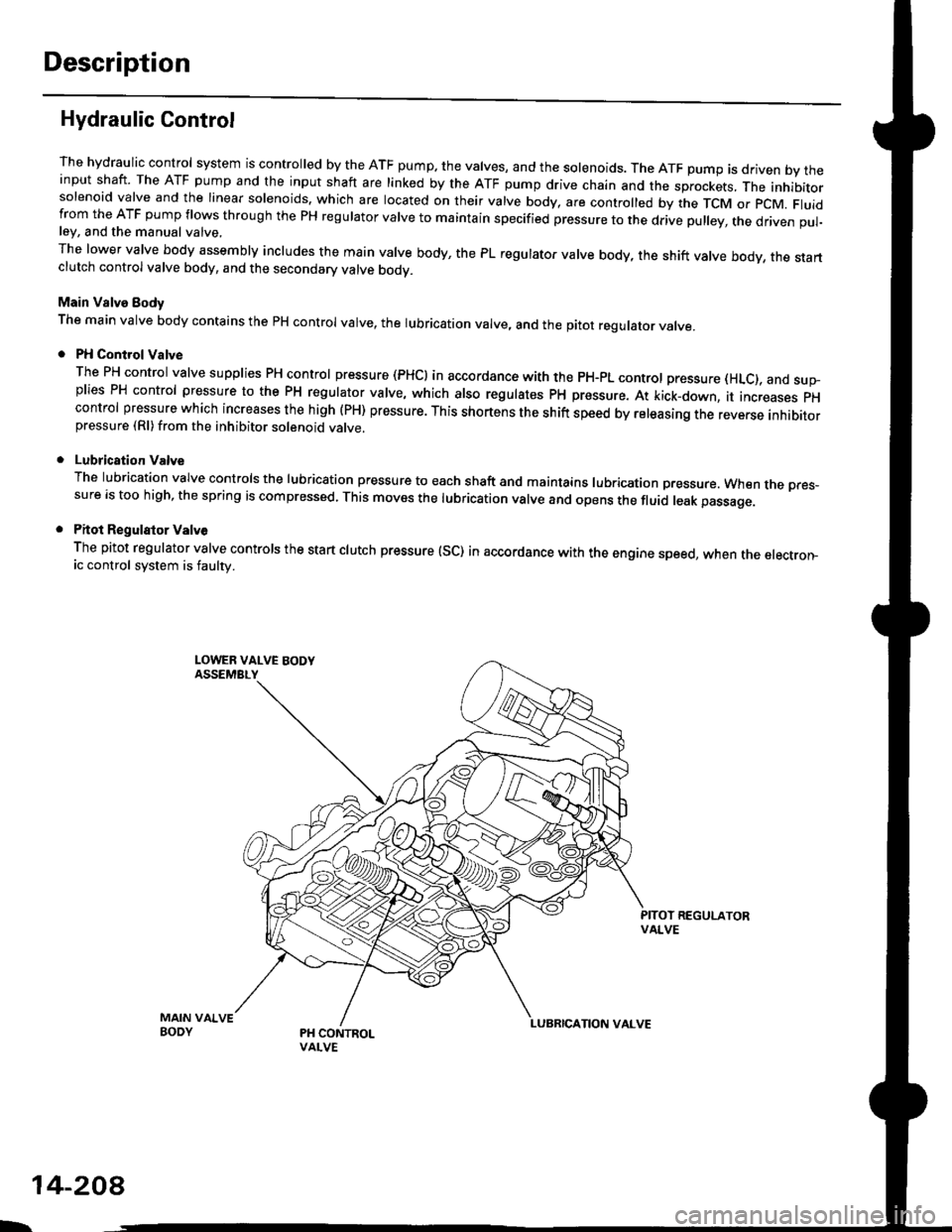
Hydraulic Control
The hydraulic control system is controlled by the ATF pump. the valves, and the solenoids. The ATF pump is driven by theinput shaft. The ATF pump and the input shaft are linked by the ATF pump drive chain and the sprockets, The inhibitorsolenoid valve and the linear solenoids. which are located on their valve body, are controlled by the TCM or pcM. Fluidfrom the ATF pump flows through the PH regulator valve to maintain specified pressure to the drive pulley, the driven pul-ley, and the manual valve,
The lower valve body assembly includes the main valve body, the PL regulator valve body, the shift valve body, the startclutch control valve body, and the secondary valve bodv.
Main Valve Eody
The main valve body contains the pH control valve, the rubrication valve, and the pitot regulator valve.
PH Control Valve
The PH control valve supplies PH control pressure (PHCI in accordance with the pH-pL control pressure (HLc), and sup-plies PH control pressure to the PH regulator valve, which also regulatss PH pressure. At kick-down, it increases pHcontrol pressure which increases the high (PH) pressure. This shortens the shift speed by releasing the reverse inhibitorpressure (Rl)from the inhibitor solenoid valve.
Lubrication Valve
The lubrication valve controls the lubrication pressure to each shaft and maintains lubrication pressure. When rne pres-sure is too high, the spring is compressed. This moves the lubrication valve and opens the fluid leak passage.
Pitot Regulalor Valv6
The pitot regulator valve controls the start clutch pressure (SC) in accordance with the engine speed, when the electron-ic control system is faulw.
MAIN VAIVEBODY
L.
14-208