1999 HONDA CIVIC Trailing arm
[x] Cancel search: Trailing armPage 1127 of 2189
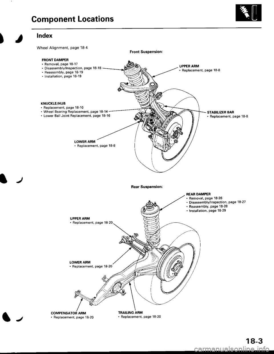
Component Locations
)
lndex
Wheel Alignment, page l8 4
FBONT DAMPER. Removal, page 18-17. Disassembly/lnspection, page 18-18. Reassembly, page 18'19. Installation, page 18-19
KNUCKLE/HUB. Replacement, page 18'10
Front Suspension:
Rear Suspsnsion:
UPPER ARM' Replscement, page 18-8
. Wheel Bearing Replacement, page 18-14. Lower EallJoint Replacement, page 18-16STABILIZER BAR' Replacement, page 18-8
LOWER ARM. Replacement, Page 18-8
UPPER ARM' Replacement, page 18 20
LOWER ARM. Replacement, page 18-20
REAR DAMPEB. Removai. page 18-26. Disassembly/lnspection, page 18-27. Feassembly, page lS-28. Installation, page 18-29
ARMTRAILING ARM' Replacement, page 18-20l-,. Feplacement, page 18 20
18-3
Page 1145 of 2189
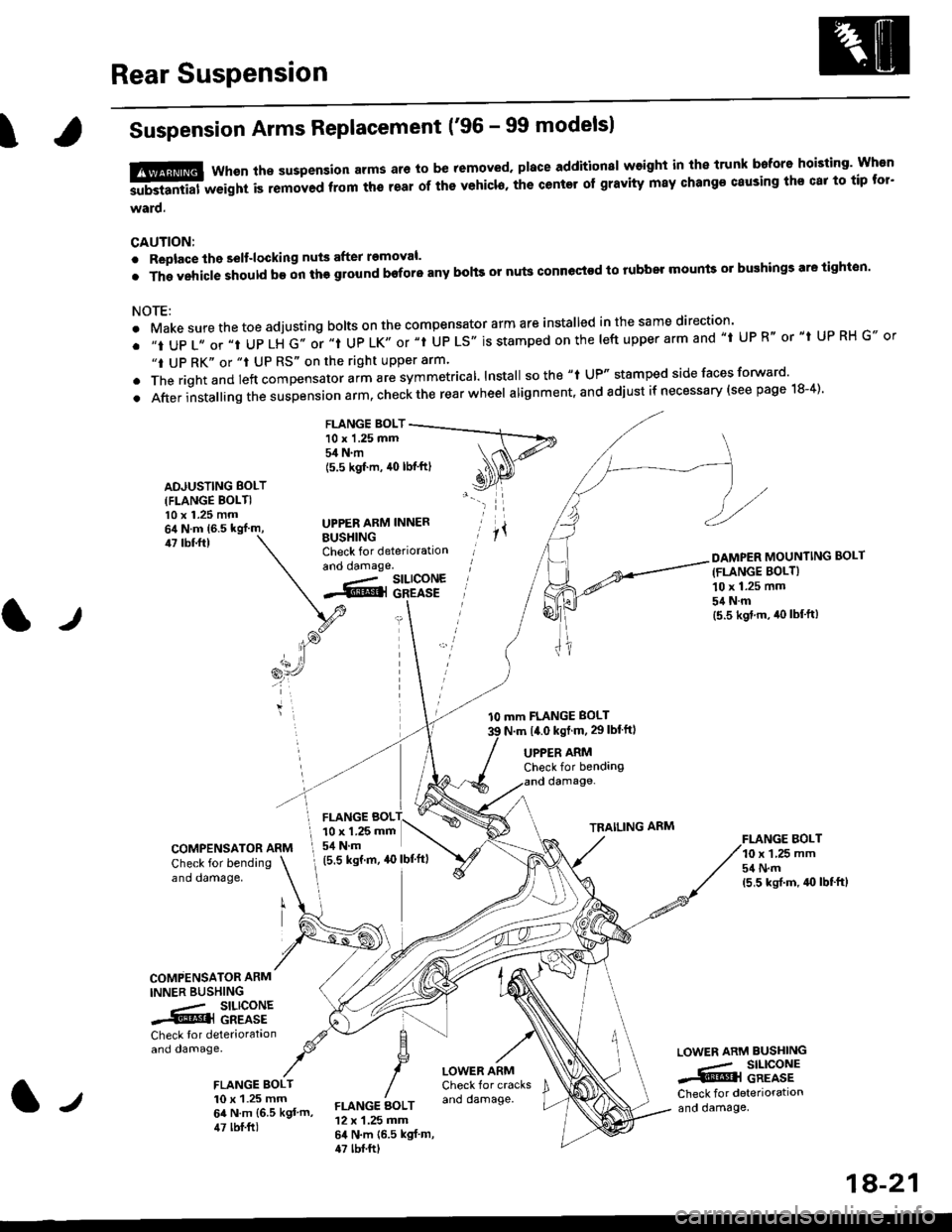
Rear Suspension
ISuspension Arms Replacement ('96 - 99 modelsl
tffi Whsn ths suspension arms ar6 to be removed. place additionsl weight in the trunk bafore hoisting' Wh€n
-substantial weight is removed ftom th6 teal of ths vehicl6, the center of gravity may change causing ths cat to tip tor'
ward.
CAUTION:
. Replace the selt-locking nuts after removal.
.Thgvehic|eshouldb€onthggroundboforeanybohsornutsconnectodtorubbelmountso]bughingsaretighton.
NOTE:
. Make sure the toe adjusting bolts on the compensator arm are installed in the same direction'
. ,,t UP 1,, or ,,t UP LH G,. or ,.t UP LK,, or "t UP LS'. is stamped on the |eft upper arm and ,,t UP R" or "t UP RH G., or
"t UP RK" or "t UP RS" on the right upper arm'
. The rightand left "ornp"n""to, uitt rre symmetrical lnstall sothe "t UP" stamped side faces forward'
.Afterinsta||ingthesuspens|onarm,checktherearwhee|alignment,andadjustifnecessary(seepagelS-4).
FLANGE BOLT10 x 1.25 mm54 N.m
ADJUSTING BOLT(FLANGE BOLTI10 x 1.25 mm
BUSHINGCheck for deteriorationand oamage.
(5.5 kgf'm, 40 lbf'ftl
UPPER ARM INNER
47 tbf.ftl
tJ
l0 mm FLANGE BOLT
N.m t4.0 kst m, 29lblftl
DAMPER MOUNTING BOLT(FLANGE BOLT}
10 x 1.25 mm
54Nm(5.5 kgd.m, iro lbf'ft)
FI.ANGE BOLT10 x 1,25 mm54 N.m(5,5 ksrf.m, 4{} lbf'ft}
UPPER ARMCheck for bendangdamage-
TRAILING ARM
COMPENSATOR ARM
Check for bendingano oamage,
COMPENSATOR ARM
INNER BUSHING
.- SILICONE.@] GREASE
Check tor deteriorataonand damage.
FLANGE BOLT10 x 1.25 mm64 N.m {6.5 kgt'm,47 lbf.ft)
LOWER ARMCheck for cracksano damage.
LOWEN ARM BUSHING
.,- SILICONE..i@l GREASECheck for deteriorationand oamage,FLANGE AOLT12 x 1.25 mm64 N.m {6.5 kgf m,47 tbf.ftt
FLANGE BOL10 x 1.25 mm
I 54 N.m
(5.5 ksrm, ao lbf'ftl
1A-21
Page 1146 of 2189
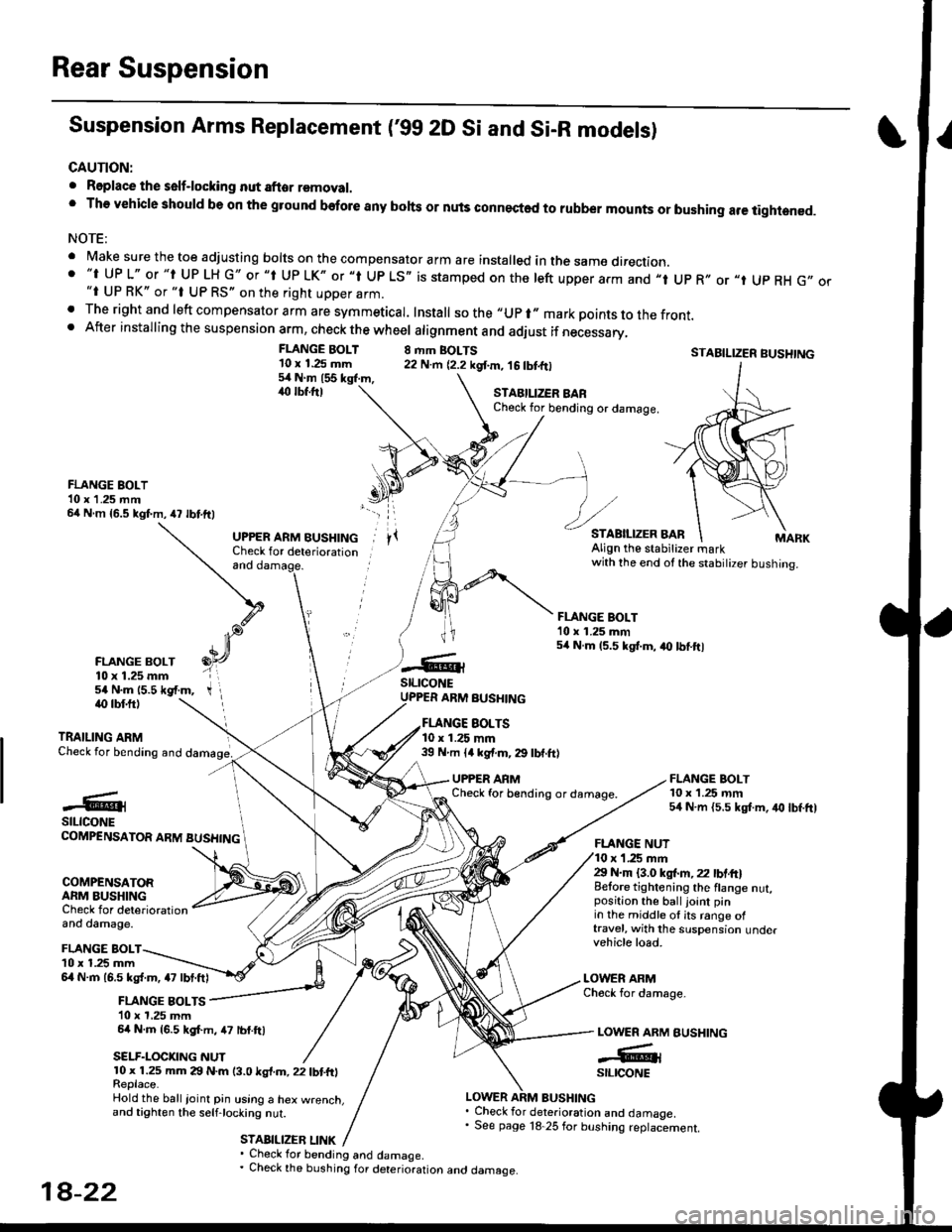
Rear Suspension
Suspension Arms Replacement ('gg 2D Si and Si-R models)
CAUTION:
. Roplace the self-locking nut after removal.' The vehicle should be on the gtound before any bohs or nuls connected to rubber mounts or bushing are tightened.
NOTE:
' Make sure the toe adjusting borts on the compensator arm are insta|ed in the same direction.. "t UP L" or "t UP LH G" or "t Up LK" or "l Up LS,, is stamped on the left upper arm and ,,t Up R,, or "t Up RH G,,"i UP RK" or "t UP RS" on the right upper arm.. The right and left compensator arm are symmeticar. Install sothe"upr"markpointstothefront.. After installing the suspension arm, check the wheel atignment and adiust if necessary,
FLANGE BOLT'10 x 1.25 mm54Nm155kgl.m,,rc lbf.ftl
8 rhm BOLTS22 N.m {2.2 kgf.m, 16 tbtfrlSTABILIZER BUSHTNG
FLANGE BOLT10 x 1.25 rnm54 N.m {5.5 kgt m, iro lbf.ft)
STAEILIZER BARCheck for bending or damage.
FLANGE BOLT10 x 1 .25 mm64 N m {5.5 kgf.m,47 lbtftl
FLANGE BOLT10 x 1.25 mm54 N.m 15.5 *gf.m,
and
UPPER ARM BUSHINGCheck for deteriorationAlign the stabitizer markwith the end ot the stabilizer bushing.
FLANGE BOLT'10 x 1.25 mm54 N.m 15.5 kgt.m, a0 lbtftl
stLrcoNEUPPER ARM BUSHINGiO lbf.ftl
TRAILING ARMCheck for bending and
EOLTS10 x 1.25 mm39 N m ll kgf.m, 29 lbf.ft)
UPPER ARMCheck for b€nding or damage.#@lstLtcoNECOMPENSATOR ARM BUSHING
COMPENSATORARM BUSHINGCheck for deteriorationand damage.
FLANGE NUTr '1.25 mm29 N.m {3.0 ksl.m,22 lbtft}Belore tightening the flange nut,position the ball joint pinin the middle ol its range oftravel, with the suspension undervehicle load.
LOWER ARMCheck for damage-
BUSHING
FLANGE BOLTl0 x 1.25 mm6l N.m 16.5 kg{.m, a7 lbt.ftl
FLANGE BOLTS10 x 1,25 mm64 N.m {6.5 kgf.m, 47 lbf.ftl
SELF.LOCKNG NUT
LOWER ARM
-GrstltcoNE10 x 1.25 mm 29 N.m (3.0 ksl.m, 22 tbtfrlReplace.Hold the ball ioinl pin using a hex w.enct.and tighten the selfjocking nut.
STABILIZEB LINK
LOWER ARM BUSHING. Check for deterioration and damaoe.' See page 18 25 for bushing replaciement.
' Check for bending and damage.. Check the bushing for deterioration ano oamage.
18-22
Page 1147 of 2189
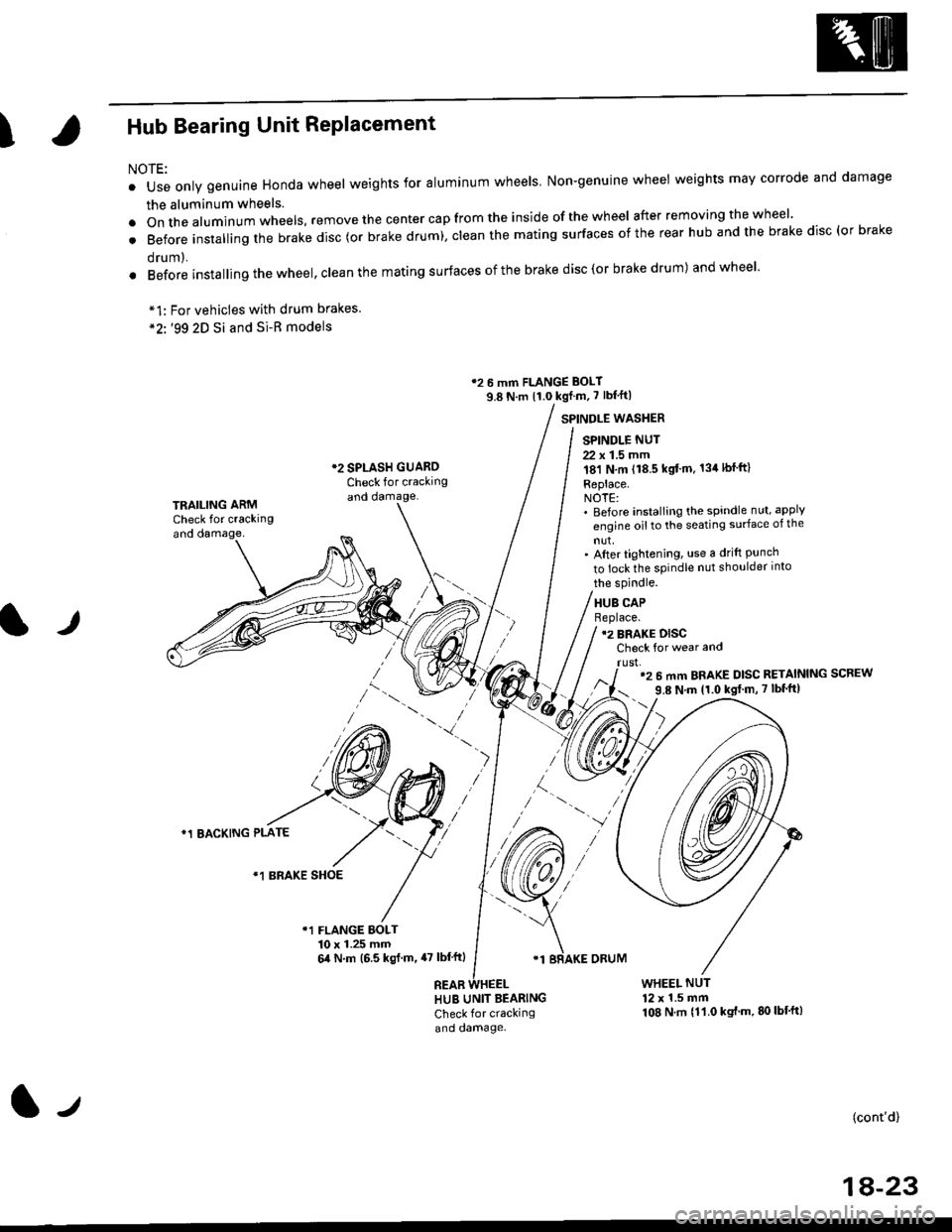
IHub Bearing Unit RePlacement
For vehicles with drum brakes.'99 2D Si and Si-B models
NOTE:
o Use only genuine Honda wheel weights for aluminum wheels Non-genuine wheel weights may corrode and damage
the aluminum wheels.
.onthea|uminumwhee|s,removethecentercapfromtheinsideoftheWhee|afterremovingthewhee|'
. Before insta||ing the brake disc (or brake drum), c|ean the mating surfaces of the rear hub and the brake disc (or brake
orum,.
. Before installing the wheel, clean the mating surfaces ofthe brake disc(or brake drum) andwheel'
*1:
*2'.
12 6 mm FLANGE BOLT
9.8 N.m {1.0 kgf m, 7 lbf'ft|
*2 SPLASH GUAROCheck for crackingand damage.
SPINDLE WASTIER
SPINDLE NUT
22 x 1.5 mm181 N,m (18.5 kgt'm. 134lbfft)
Replace.NOTE:' Before installing the spindle nut, apply
engine oil to the seating surface of the
nut,' After tightening, use a drift Punchto lock the spindle nut shoulder into
TRAILING ARMCheck for crackingand oamage,
lr
the spindle.
HUB CAPBeplace.12 BRAKE DISCCheck for wear and
rust,'2 6 mm BRAKE DISC RETAINING SCREW
9.8 N'm 11.0 kgt m, 7 lbf'ft|
)
*1 BACKING PLATE
/\*1 BRAKE SHOE
r1 FLANGE BOLT10 x 1.25 mm6,0 N.m (6.5 ksl.m,47 lbl'ftl
REAB
'1 BRAKE ORUM
HUB UNIT BEARING
Check for crackingand damage.
WHEEL NUT12 x 1.5 mm108 N.m {11.0 kgt'm.80lbt'ft)
(cont'd)
1A-23
l-t
Page 1150 of 2189
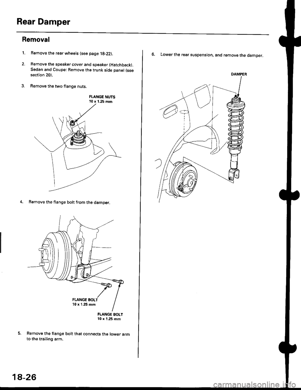
Rear Damper
Removal
1. Bemove the rear wheels (see page 1g-22).
2. Remove the speaker cover and speaker (Hatchback).
Sedan and Coupe: Remove the trunk side panel (see
section 20).
3. Remove the two flange nuts.
FLANGE NUTS10 x 1.25 mm
4. Remove
FLANGE BOLT10 x 1,25 mm
Remove the flange bolt that connects the lower armto the trailing arm.
the flange bolt from the damper.
FLANGE BOLT'10 x 1 .25 mm
18-26
6. Lower the rear suspension, and remove the damper.
Page 1178 of 2189
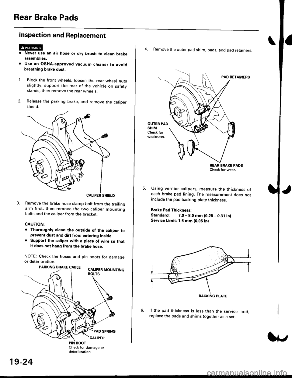
Rear Brake Pads
Inspection and Replacement
Never use an air hose or dry brush to clean brakeassemblies.
Use an OsHA-apptoved vacuum cl€aner to avoidbreathing brake dust,
Block the front wheels, loosen the rear wneet nutsslightly, support the rear of the vehicle on safetystands, then remove the rear wheels.
Release the parking brake, and remove the calioersh ield.
CALIPER SHIELD
Remove the brake hose clamp bolt from the trailingarm first, then remove the two caliper mountingbolts and the caliper from the bracket.
CAUTION:
. Thoroughly clean the outside of the caliDer toprevent dust and dirt trom entering inside.. Support the calipor with a pieco of wire so thatit does not hang fuom the brake hose.
NOTEr Check the hoses and pin boots for damageor deterioration.
PARKING BRAKE CABLE ^.. ._-_ ---.
'L
19-24
4. Remove the outer pad shim, pads, and pad retainers.
PAO RETAINERS
OUTER PAOSHIMCheck for
REAR BRAKE PADSCheck for wear.
Using vernier calipers, measure the thickness ofeach brake pad lining. The measurement does notanclude the pad backing plate thickness.
Brake Pad Thickness:
Standard: 7.0 - 8.0 mm {0.28 - 0.31 in}Service Limit: 1.5 mm {0.06 in}
lf the pad thickness is less than the service limit,replace the pads and shims together as a set.
BACKING PI-ATE
Page 1179 of 2189
I
7.
11.
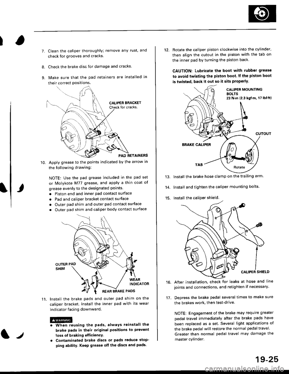
Clean the caliper thoroughly; remove any rust, and
check for grooves and cracks.
Check the brake disc for damage and cracks.
lvlake sure that the pad retainers are installed in
their correct positions.
PAD RETAINERS
Apply grease to the points indicated by the arrow in
the following drawing:
NOTE: Use the pad grease included in the pad set
or lMolykote M77 grease, and apply a thin coat of
grease evenly to the designated points.
. Piston end and inner pad contact surface
. Pad and caliper bracket contact surface
. Outer pad shim and outer pad contact surface
. Outer pad shim and caliper body contact surface
lnstall the brake pads and outer pad shim on the
caliper bracket. Install the inner pad with its wear
indicator facing downward.
@iwhen reusing the pads, always reinstall the
brake pads in iheil original posiiions lo prevont
loss ol braking efficiency
. Contaminaled brake discs or pads reduce stop-
ping ability. Keep grease off the discs and pads.
t./
19-25
12. Rotate the caliper piston clockwise into the cylinder'
then align the cutout in the piston with the tab on
the inner pad by turning the piston back
CAUTION: Lubricate ths boot with rubber grease
to avoid twisting the piston boot. lf the piston boot
is twisted, back it out so it sits properly.
CALIP€R MOUNTINGBOLTS23 N,m {2.3 kg{.m, 17 lbt'ft)
13.
14.
15.
CUTOUT
BRAKE CALIPER
Install the brake hose clamp on the trailing arm.
Install and tighten the caliper mounting bolts.
Install the caliper shield.
After installation. check for leaks at hose and line
joints and connections, and retighten if necessary.
Depress the brake pedal several times to make sure
the brakes work, then test-drive
NOTE: Engagement of the brake may requrre greater
pedal travel immediately after the brake pads have
been replaced as a set. Several light applications of
the brake pedal will restore the normal pedal travel.
Greater than normal pedal travel may damage the
master cylinder.
16.
17.
Page 1230 of 2189
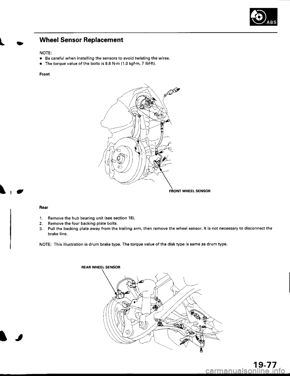
l}tWheel Sensor Replacement
NOTE:
. Becareful when installingthe sensors to avoid twisting the wires.
. The torque value of the bolts is 9.8 N.m (1.0 kgf.m, 7 lbf.ft).
Front
FRONT WHEEL SENSOR
Rear
1. Remove the hub bearing unit (see section 18).
2. Remove the four backing plate bolts.
3, Pull the backing plate away from the trailing arm, then remove the wheel sensor. lt is not necessary to disconnect the
brake line.
NOTE: This illustration is drum brake type. The torque value of the disk type is same as drum type.
REAR WHEEL SENSOR
J\
It
19-77