Page 461 of 2189

ldle Control System
ldle ControlSystem
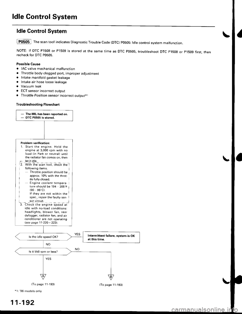
lF0505 l Th" """n tool indicates Diagnostic Trouble Code (DTC) PO5O5: tdte controt system malfunction.
NOTE: lf DTC P1508 or P1509 is stored at the same time as DTC P0505, troubleshoot DTC p1508 or p1bog first. thenrecheck for DTC P0505.
Possible Cause
. IAC valve mechanical malfunction
. Throttle body clogged pon, improper adjustment. Intake manifold gasket leakage
. Intake air hose loose leakage
. Vacu um leak
. ECT sensor incorrect output
. Throttle Position sensor incorrect output*r
Troubleshooting Flowchart
The MIL has been reoorted on.DTC P0505 is stored.
Problem verification:1. Start the engine. Hold theeng;ne at 3,000 rpm with noload (jn Park or neutral) untilthe radiator fan comes on, then*r let it idle.t2. with rhe scan toot, ct'eit Ge l
Throttle position should beapprox. 10% with the throttle fully closed.E ngine coolant tempera-ture should be 194 205'F(90 96.Ci.lf they are not within thespec., repair the faulty sen
L._ _9oI9[cr]41 l3. Chec& the engine speed atidle with no-load cond;tionsiheadlights, blower fan, reardefogger, radiator fan, and airconditioner are not operating\see page l1-22O - 223).
Intermittent tailure, system is OKat this time.ls the idle speed OK?
ls it 550 rpm or less?
(To page 11,193)
*1r'96 models only
11-192
(To page ll-193)
Page 736 of 2189

Electrical Troubleshooting ('96 - 9g Modelsl
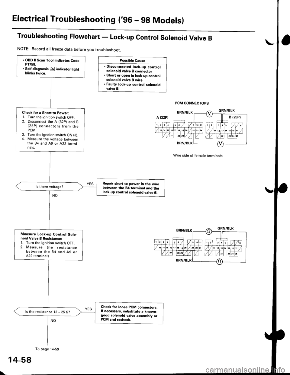
Troubleshooting Ftowchart - Lock-up control sorenoid Varve B
Possible Cause
. Disconnected lock-up controlsolenoid valve B connector' Short or open in lock-up controlsolonoid valve B whe. Faulty lock-up control solenoidvalve B
PCM CONNECTORS
Wire side of female terminals
. OBD ll Scan Tool indicrtes CodeP1758.. Self-diagnosis E indicrtor lightblinkstwice.
Check for a Shon to Power:1. Turn the ignition switch OFF.2. Disconnect the A (32p) and B(25P) connectors from thePCM,3. Turn the ignition switch ON t).4. Measure the voltage betweenthe 84 and A9 or A22 termi-nals.
Repeir short to power in the wirebetween the 84 teiminal and thelock-up control solenoid valve B.
Moasure Lock-up Control Sole-noid Valve B Resistance:1. Turn the ignition switch OFF.2. Measure the resistancebetween the 84 and Ag orA22 terminals.
Check for loose FCM connectors,lf necessary, substitute a known-good solenoid valve assembly olP1CM and rech6ck.
ls the resistance 12 - 25 O?
NOTE: Record all freeze data before you troubleshoot.
A {32P)
To page 14-59
t-
Page 740 of 2189

Electrical Troubleshooting ('96 - gg Modelsl
Troubleshooting Flowchart - A/T Gear position Switch (Open)
. OBD ll Scan Tool indicates CodeP1706.. Self-di.gnosk E indicator tightblinks six timos.
Measure ATP 04 Voltege:1. Shiftto E position.2. Measure the voltage betweenthe 824 and A9 or A22 terminals,
ls there voltage?
Possible Causo
. Disconnected A/T gear positionswitch conn€ctor. Open in A/T gear positionswitch wire. Faulty A/T gear position switch
Wire side of female terminals
NOTE: Record all freeze data before you troubleshoot.
Moasure ATP I Voltage:1. Turn the ignition switch ON 1 ).2. Shift to E position.3. Measure the voltage betweenthe B'f6 and Ag ot A22 tetmi-nats.
Ropai. op€n in the wire betwe€nthe Bl6 terminal.nd the A/T gearposition swhch.
Measur€ ATP NP Voltage:1. Shift to E or E position.2. Measure the voltage betweenthe 825 and A9 or A22 termi,nals,
Repeir open in the wir€ betweentho B25 terminal and th6 A/T geerposition indicator or tho A/T 96.rposition 3witch.
Rcpair open in the wire betweentto 82{ to.minal and th6 A/T geatlrosition 3witch.
To page 14 63
PCM CONNECTORS
NO
1
L
+62
Page 742 of 2189

Electrical Troubleshooting ('96 - 98 Modelsl
Troubleshooting Flowchart - Shift Gontrol Solenoid Valve A
Po$ible Cau3e
. Disconnected shift controlsolenoid valve A connector. Short oi open in shift controlsolenoid valve A wire. Faulty shirt control solenoid
PCM CONNECTORS
' OBD ll Scan Tool indicates CodeP0753.. Sett{iagnosis E indicator lightblinks seven tim6.
Check tor a Short to Power:1. Turn the ignition switch OFF.2. Disconnect the A (32P) and B{25 Pi connectors trom thePCM.3. Turn the ignition switch ON {ll).4. Measure the voltage betweenthe 83 and A9 orA22 terminals.
Repair short to powe. in the wir6between the 83 terminal .nd theshift control solonoid valvo A.
Moa3ure Shift Control SolenoidValve A Resistanc€:1. Turn the ignition switch OFF.2, Measure the resistancebetween the 83 and A9 or A22terminals.
Ch€ck for loose PCM connectors.lf n€c6srry, subatitute a known-good solenoid valve a3,sembly orPCM end rocheck.
ls the resistance 12 - 25 0?
NOTE: Record all freeze data before you troubleshoot.
A t32Pl
To page 14-65
Wire side ol female terminals
Page 744 of 2189

Electrical Troubleshooting ('96 - g8 Modelsl
Troubleshooting Flowchart - Shift Control Solenoid Valve B
Possible Cause
' Disconnected shift controlsolenoid valve I connectol. Short or open in shift controlsolenoid valve B wire. Faulty shift control 30lenoidvalve B
PCM CONNECTORS
Wire side ot female terminals
. OBD ll Scan Tool indic.tes CodeP0758.. Solt-diagnosis E indicator lightblinks eight times.
Chock for a Short to Power:1. Turn the ignition swatch OFF.2. Disconnect the A (32P) and B(25P)connectors from the PCM.3. Turn the ignition switch ON (ll).4. Measure the voltage betweenthe 811 and Ag or A22 termi-nals,
Repair short to powar in the wirebotwcen the 811 torminal andthe shift control solenoid valve 8.
Measure Shift Cont.ol SolenoidValve B Resktance:1. Turn the ignition switch OFF.2, Meas u re the resistancebetween the Bll and A9 orA22 terminals.
Checl for loose PiCM connector3.lf nec€ssary, sub3titute a known-good solenoid v.lve assembly olPCM and recheck.
ls the resistance 12 - 25 O?
NOTE: Record allfreeze data before you troubleshoot,
A t32P)
To page 14 67
\
Page 748 of 2189

Electrical Troubleshooting ('96 - 98 Modelsl
Troubleshooting Flowchart - Mainshaft Speed Sensor
NOTE: Record all freeze data before you troubleshoot.
Po$ible Cause
. Disconnect€d mainshaft sD€edSensor @nnoctot. Short or open in mainshattsJt€ed s6nsoa wire. Faulty mainshaft lpeed s6nso.
NOTE: Code P0715 (15) on the PCMdoesn't always mean there's an electricalproblem in the mainshaft or countershaftspeed sensor circuit; code P0715 (15)may also indicate a mechanical problemin the transmission.
MAINSHAFT SPEEOSENSOR CONNECTOR
Terminal side of male terminals
PCM CONNECTOR B I25PI
. OBD ll Scan Tool indicates Codem715.. Self-dirgnosi3 E indicatorlight indicstes Code 15.
Check the mainshaft and counter-shaft speed sensor installation.
Are the mainshaft and countershaftspeed sensor installed properly?
Moasure Mainshaft Spoed SgnsolRosistance at the Sensor Con-n€ctor:1. Disconnect the 2P connectorfrom the mainshaft speed sen-sor connector.2. Measure the resistance ot themainshaft speed sensor.
ls the resistance 400 600 O?
Check Mainshaft Sp6ed Sensorfor a Short Circuil:1. Disconnect the B {25P) connec'tor lrom the PCM.2. Check for continuity betweenbody ground and 815 terminaland the 814 terminal individu,
Repai. shon in the wi.os bstwoenthe 815 and 814 te.minals andthe mainshatt .Dood 3ensor.
ls there continuity?
To page 14-71
14-70
Wire side of female terminals
Page 750 of 2189

Electrical Troubleshooting ('96 - 98 Modelsl
Troubleshooting Flowchart - Linear Solenoid
NOTE: Record all freeze data before vou troubleshoot,
Po$ible Caus6
. Disconnoctod lineaJ solonoidconnectot. Short or open in linoar solenoid
' Faulty linoar solonoidLINEAR
Terminal side ol male terminals
PCM CONNECTOR B I25PI
Wire side of female terminals
SOLENOID CONNECTOR
l;r]l
TT
YI
LI
REDWHT
OBO ll Scan Tool indicates CodeP176a.Self-diagnosi3 E indicatorlight indicates Code 16,
Measure Linear Solenoid Resist-ance at the Solenoid Connecto.:1. Turn the ignition switch OFF.2. Disconnect the 2P connectorlrom the linear solenoid connector,3. Measure the resistance ofthelinear solenoid.
ls the resistance approx. 5.0 O?
Check Linear Solenoid for a ShonCircuit:1. Disconnect the B 125P) connec-tor from the PCM.2. Check for continuity betweenthe body ground and the B1terminal and 82 terminal inda-vidually.
Repair short in the wires bgtwoenthe Bl and 82 terminab and thelineti solsnoid.
Meaaure Linoar Solenoid RGi3t-anc€:1. Connect the linear solenoidconnector.2, Meas u re the resistancebetween the 81 and 82 termi-nals,
Ropair looso terminal or open inthe wires botwe€n the 81 and 82telminals end the linear solenoid.
ls the resistance approx. 5.0 O?
To page 14-73
14-72
Page 752 of 2189

Electrical Troubleshooting ('96 - 98 Models)
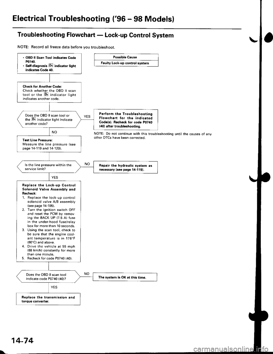
Troubleshooting Flowchart - Lock-up Control System
NOTE: Record all freeze data before vou troubleshoot.
Possible Cause
Faulty Lock-up cont.ol system
NOTE: Do not continue with this troublesnoonnoother DTCS have been corrected.until the causes of any
. OBD ll Sc6n Tool indicatG Codem7{0.. Self-diagnosis E indicator lightindicates Code 40.
Check tor Another Code:Check whether the OBD ll scantool or the E indicato, lightindicates another code.
Perform lhe Troublo3hooiingFlowchart tor the indicatedCode(s). Recheck for cod. P07il0lilol aftor iroubl€3hooting.
Does the OBD ll scan tool orthe E indicator light indicateanother code?
Tast Line Pressure:Measure the line pressure (seepage 14-119 and 14-120).
Repair tho hydreulic aystem a3necessary {3ee page 14-119).
Replace the Lock-up ControlSolenoid Valve Assembly andR6check;1. Beplace the lock up controlsolenoid valve Ay'B assembly(see page 14-105).2. Turn the ignitaon switch OFFand reset the PCM by removing the BACK UP (7.5 A) fusein the underhood fuse/relaybox for more than 10 seconds,3. Using the scan tool, check tobe sure that the engine coolant temperature is in 176'F(80'C) and above.4. Drive the vehicle at 55 mph(88 km/h) constantly for morethan one minute.5. Recheck for code P0740 (40).
Does the OBD ll scan toolindicate code P0740 {40)?The systom k OK at this time.
l'.
14-74