1999 HONDA CIVIC Fault code
[x] Cancel search: Fault codePage 956 of 2189

Troubleshooting Flowchart - Drive Pulley Speed Sensor
NOTE: Record allfreeze data before you troubleshoot'
Possible Cau3€
. Disconnected diive PulleYsoeed s6n3or connectol. Short or open in drive Pull.Ysooed sonsor wire. FaultY drive PulleY spo€d sen'
301
DRIVE PULEY SPEED
SENSOR @NNEfiOR
Terminal side of male terminals
PCM CONNECTOR D (16PI
NDR SG IGRNI
Wire side o{ Iemale terminals
(cont'd)
14-279
.OBD ll Scan Tool indicates
Code Pl885.. Selt-diagnosb E indicator light
indicatos Code 34
check the drive pulleY sPeed sen-
sor installation, and check it for
damage.
ls the drive PulleY speed sen-
sor installed properly, and not
damaged?
Rein3tall or roplace and techeck
Measuro Drive PulleY Speed Sen_
sor Ro3istanco at the Sonsol
Connector:1. Disconnect the 2P conneclor
from the drive Pulley speed
sensor,2. Measure drive Pulley speed
sensor resislance at the sen-
sor connecror.
ls the resistance 350 - 600 O?
Check Drivo PulleY SP6€d Sen3o.
lor . Short Circuit:1. Disconnect the D {16P) connec-
torlrom the PCM.
2. Check lor continuity between
body ground and the D11 ter
minal and D'l2 terminal indi
vidually.
Repai. short in the wiles
between the Dll lnd D12 termi-
nals and iho drive Pull.Y speed
To page 14-280
Page 958 of 2189

Troubleshooting Flowchart - Driven Pulley Speed Sensor
NOTE: Record all freeze data betore you troubleshoot'
Po3sible Caus€
' Oisconnected driven PulleYspeed s6nlor connoctor. Short or opon in d.iven Pulleysoeed sonsol wirc. Faulty driven Pulley speed sen_
sor
DRIVEN PULLEY SPEED
SENSOR CONNECTOR
Terminal side ol male terminals
FCM CONNECTOR D If6P)
NDN IWHTI
Wire side of female terminals
(cont'd)
'OBD lt Sc.n Tool indicates
Code Pl886.. Self-diagnosb E indicator light
indicrt€. Codo 35.
Check the driven Pulley speed
sensor installation, and check it
Ior damage.
lsthe driven pulleY speed sen'
sor installed ProPerly, and not
damaged?
Boin3tall or ropl.ca and recheck.
M..sure Drivon PulloY SPoed
Sonsor Rosblanco at the S6n3or
Conn6ctori1. Disconnect the 2P connector
trom the driven PUlley sPeed
sensor,2. lveasure driven Pulley speed
sensor resistance at the sen_
sor connector.
ls the resistance 350 - 600 0?
Check Dtivon Pulloy SP€ed Sen'
sor for a Short Circuit:
1. Disconnect the D (16P) connec-
torfrom the PCM.
2. Check tor continuity between
body ground and the D10 ter'
minal and Dl6 terminal indi-
vidually.
Raoair shott in tho wi.6s
betwoon th. Dlo end D16 tormi'
nak .nd the ddven Pulley spo€d
Fo page 14'282
14-2A1
Page 960 of 2189

Troubleshooting Flowchart - Secondary Gear Shaft Speed Sensor
NOTE: Record all freeze data before you troubleshoot
Po$ible Causo
. Oisconnectod secondarY gear
shaft speed sensor conn66or' short or open in secondary gear
shaft spe€d sensor wiro. Faulty secondarY gear 3haft
sPeed sensor
SECONDARY GEAR SHAFT
SPEEO SENSOR CONNECTOR
Terminal side of male terminals
PCM CONNECTOR D I15P)
VEL (WHT/REO) VEL SG IALK/WHTI
Wire side oI female terminals
(cont'd)
14-243
' OBD ll Scan Tool indicates
Code P1888.. Self-diagnosis E indicalor light
indicats Code 35.
Check the secondarY gear shaft
speed sensor installation, and
check it for damage.
ls the secondary gear shaft
speed sensor installedproperly, and not damaged?
Reinatall or replace and rocheck.
Measure SocondarY Gear Sh.ft
Speed Sen3or Resistance at the
Sensor Connector:1. Disconnect the 2P connector
trom the secondary gear shaft
speed sensor.2. Measure secondary gear shaft
speed sensor resistance at the
sensor connector.
ls the resistance 350 - 600 0?
Check SecondarY Gear Shaft
Speed Sensor lor a Short Circuit:
1. Disconned the D (16P) connec-
tor from the PCM.
2. Check for continuity between
body ground and the D1 ter-
minal and D7 terminal indi-
vidually.
Repair short in the wiros
b.tween the Dl and D7 termi_
ne13 and th€ secondarY geal
3haft lpeed sonsor.
To page 14-284
Page 962 of 2189

Troubleshooting Flowchart - Shift Control System
NOTE: Record allfreeze data before you troubleshoot
Possible cause
Faultv shift control svstem' OBD ll Scan Tool indicates Codo
P1Ato.. Self-diagnosis E indicator light
indicatos Code 42.
Check for Anoth€r Code:Check whether the E indicator
light indicates another code.
P€rform the Tloubleshooting
Flowchart for the indicated
Code(sl.
ls the E indicator light indi
cate another code?
Check Stall Speed RPM:
Measure the stall sPeed RPM(see page 14-298).
ls the stall speed over 3,500 rpm?
ls the stall speed below 2,000 rpm?
Test-drive and Check Engine
Speed:L Drive the vehicle at 30 mph
150 km/h) constantly for sev-
eral mlnutes.2. Check the engine speed
ls the engine speed within the
specification (see Page 14'296
and 14'297)?
14-245
Page 963 of 2189

Electrical Troubleshootang ('gg - 00 Models)
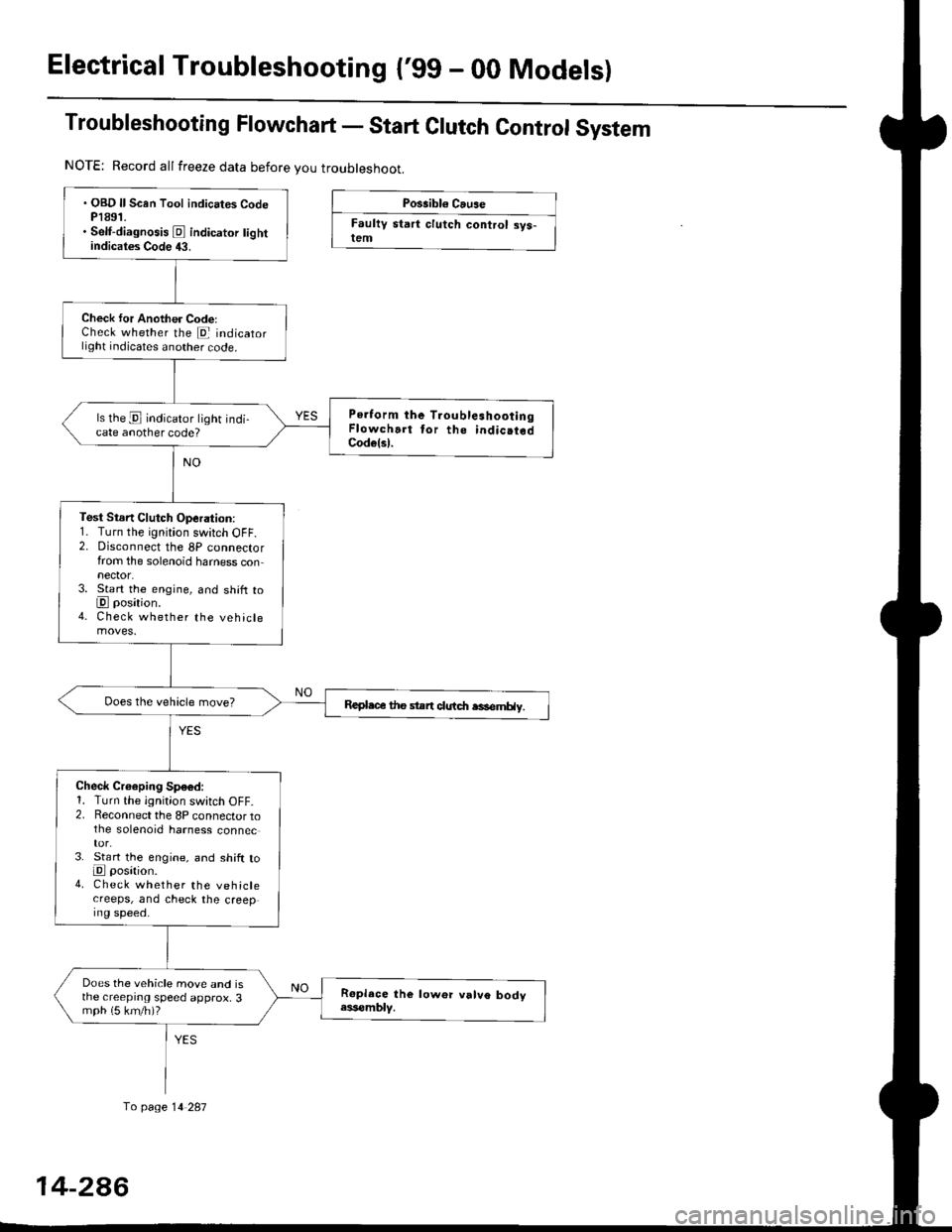
Troubleshooting Flowchart - Start Clutch Control System
Possibl€ Cause
Faultv start clutch control sys-lem
NOTE: Record allfreeze data before you troubleshoot.
fo page 14 287
. OBD ll Scan Tool indicates CodeP1891.. Self-diagnosis E indicator tightindicates Code 43.
Check for Another CodelCheck whether the E indicatorlight indicates another code.
Perform the TroubleshootingFlowchart tor the indic.tedCodelsl.
ls the E indicator light indi-cate another code?
Test Stsn Clutch Operation:1. Turn the ignition switch OFF.2. Disconnect the 8P connectorfrom the solenoid harness connector.3. Start the engine, and shift toE position.4. Check whether the vehiclemoves.
Repl.c€ the stan clutdt rasemHy.
Check Croeping Sp€6d:1. Turn the ignition switch OFF.2. Reconnect the 8P connector tothe solenoid harness connec
3. St€rt the engine, and shift toE posation.4. Check whether the vehiclecreeps, and check the creeping speed.
Does the vehicle move and isthe creeprng speed approx, 3mph (5 km/h)?
14-2A6
Page 1207 of 2189

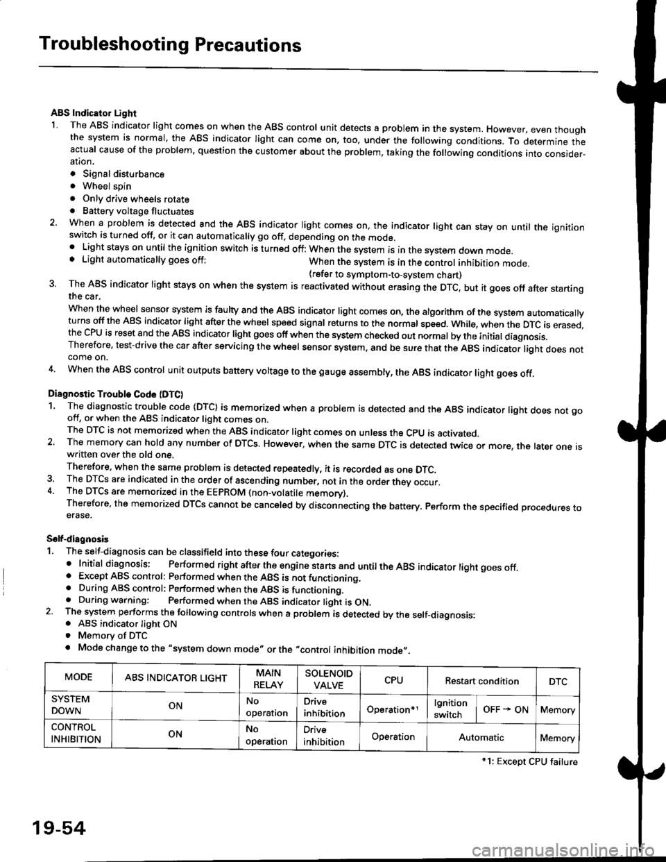
Troubleshooting Precautions
ABS Indicator Light
I The ABS indicator light comes on when the ABS control unit detects a problem in the system. However, even thoughthe system is normal, the ABs indicator light can come on, too, under the following conditions. To determine theactual cause of the problem, question the customer about the problem, taking the following conditions into consider-ation.
. Signal disturbance
. Wheel soin
. Only drive wheels rotate. Battery voltage fluctuates
2. When a problem is detected and the ABS indicator light comes on, the indicator light can stay on untat the ignitionswitch is turned off, or it can automatically go off, depending on the mode.. Lightstayson until the ignition switch isturned off;When the system is inthesvstem down mode.o Light automatically goes off:When the system is in the control inhibition mode.(refer to symptom-to-system chart)3 The ABS indicator light stays on when the system is reactivated without erasing the DTC, but it goes off after startingthe car.
when the wheel sensor system is faulty and the ABS indicator light comes on, the algorithm of the system automaticallyturns off the ABS indicator light after the wheel speed signal returns to the normal speed. while, when the DTC is erased,the CPU is reset and the ABS indicator light goes off when the system check€d out normal by the initial diagnosis.Therefore, test-drive the car after servicing the wheel sensor system, and be sure that the ABS indicator light does notcome on.
4. When the ABS control unit outputs battery voltage to the gauge assembty, the ABS indicator light goes off.
Diagnostic Trouble Code (DTC)
1. The diagnostic trouble code (DTC) is memorized when a problem is detected and the ABS indicator light does not gooff, or when the ABS indicator light comes on.The DTC is not memorized when the ABs indicator right comes on unress the cpU is activated.2. The memory can hold any number of DTCs. However, when the same DTc is detected twice or more, the later one iswritten over the old one.
Therefore. when the same problem is detected repeatedly, it is recorded as one DTC.3. The DTCS are indicated in the order of ascending number, not in the order thev occur.4. The DTCS are memorized in the EEpROM {non-volatile memorv}.Therefore, the memorized DTCS cannot be canceled by disconnecting the battery. perform the specified orocedures toerase.
Solf-diagnosis
1. The self-diagnosis can be classifield into these four categories:' Initial diagnosis; Performed right after the engine sta rts and untiltheABs indicator light goes off.o Except ABS control: Performed when the ABS is not functioning,. During ABS control: Performed when the ABS is functioning.. During warning: Performed when the ABS indicator light is ON.2 The system performs the following controls when a problem is detected by the self-diagnosis:. ABS indicator light ON. Memory of DTC
. Mode change to the "system down mode,, or the "control inhibition mode,,.
MODEABS INDICATOR LIGHTMAIN
RELAY
SOLENOID
VALVECPURestart conditionDTC
SYSTEM
DOWNONNo
operal|on
Drive
inhibitionOperation+rlgnition
switchOFF - ONMemory
CONTROL
INHIBITIONONNo
operat|on
Orive
inhibitionOperationAutomaticMemory
*1: Except CPU failure
19-54
Page 1211 of 2189

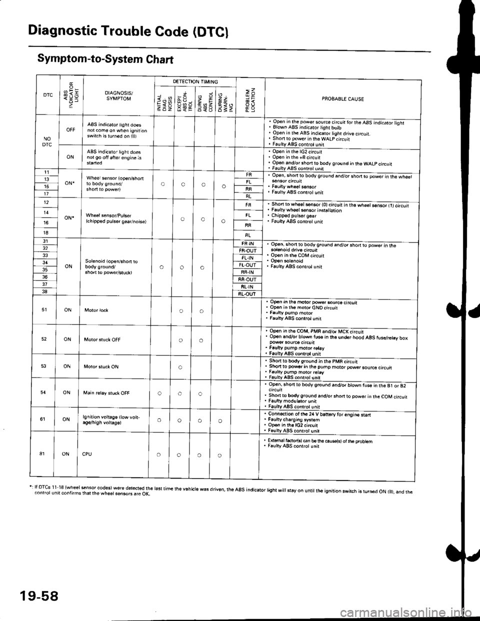
Diagnostic Trouble Code (DTCI
Symptom-to-System Chart
DTC
oH1=DIAGNOSIS/SYMPTOM
DETECTION TIMING
>=PNOBABLE CAUSEi.'sEV98€E
zr\9=6<_6
=t
6tz
NODTC
ABS indicator iighr doesnot com€ on when ignirionswrt.h is lu.ned on (ll)
, Open in the pow€. source circ!ir ror the ABS -.ndicato;l isht. Elown ABS indicalo.lighr butb' Open in rhe ABS indicaror tight drive cncuit.. Shori ro pow€r in theWALpcircuit. FaultyABS contrct!nit
ONABS indicator light doesnol90 oft 6frer engine isOpen in the lG2 circuitOpon in the +B circuirOp€n andlor short ro body ground jn the WALP circuitFaultv AAS coni.ol unnt1
oN.Wheel sensor (op€n/shortOooo13upen, snofiro bodyground and/or shodro power in rhe wh€61
Faulty ABS co.lrctunitllBL12
oN.(chipp€d pulser gea/noise)oao
Short to wh6sls€n6or (O)circuir in t'e.h;;Go-nso, trtcircutiFaulty whsel s€nsor insra|ation
Faulty ABS cont.olunir
I8
31
ONSolenoid (open/shon roaoa
Op.ni shon to bodyground and/o. shorrto powsr in rhe
op€n in lh6 coM circuit
Faulty ABS conlrclunit
32F8-OUTFL.IN3'lFT.OUTRF.IN88 OUT318t rN38RLOUT
ONoo
op€n in tho motor pow€..ourco circliaOp€n inih€ moro.cNOcircuit
Faulty ABS conrrol unit
52ONoo
Open in rh€ COM, PMR 6nd/o. MCKcircuirOp€n.n.Vor blown lus€ in the under hood AgS rusdretry box
Faufty pump moto. rotayfaulv ABS conlrolunit
53ONo
. Sho.tto bodygrou.d in the pMR circuit. Shon to powsr in tha puhp moror pow6rsource circu. r.urty pump motor.etay, FalltyABS contolunit
54ONooc
Open, rhorr ro bodygrcund and/or blown fus€ in the B1 or 82
Shonto body ground.n.Vor short to powor in rhe COM circuitFaulty modul.tor unnFaulty ABS controt unit
ONlgnition voltage (low vott-oooo
. Connection ot the24 V bariorv tor enqins starr. Faurtycharoins system. Op€n in th6lG2 circuit. Fa!lly ABS contrcl unil
81ONCPUoooo
E {€rml facior{sl en bs rhe ouse{sl ot |he probtemF.ulty ABS conrrot unit
r: It DTcs 1 1 18 {wheel sensor codes) wore del*ted the lasr time the v6h cls wEs d riv€n, rhe a8s indicator tight wi
stay on u ntit lh6 ignition swirch is rurn6d oN t), and theconnorunit contnms rhat rhe wheet sensoB . rc OK,
19-58
Page 1394 of 2189

Troubleshooting -'99 - 00 Models
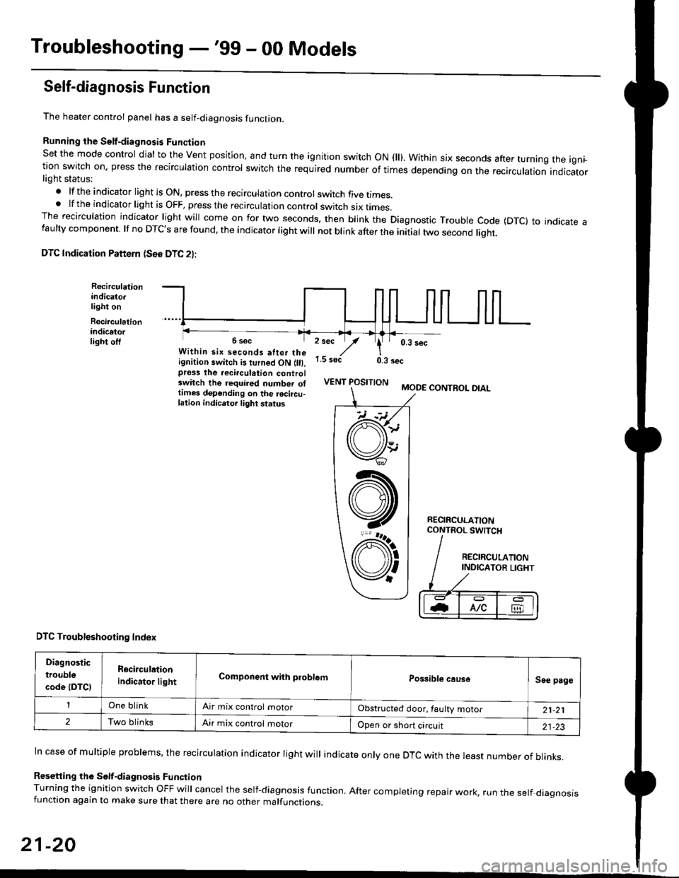
Self-diagnosis Function
The heater control panel has a self-diagnosis function.
Running the Self-diagnosis Funqtion
Set the mode control dial to the Vent position, and turn the ignition switch ON fll). Within six seconds after turnang the igni_tion switch on. press the recirculation control switch the required number of times depending on the recirculation indicatorlight status:
.lftheindicatorlightisON,presstherecirculationcontrolswitchfivetrmes.
.lftheindicatorlightisOFF,presstherecirculationcontrol switch six rrmes.The recirculation indicator light will come on for two seconds. then blink the Diagnostic Trouble code {DTc} to indicate afaulty component. lf no DTc's are found, the indicator light will not blink after the initial two second liqht.
DTC Indication Pattern (S6e DTC 2l:
Recirculationindicato.light on
Recirculationindicatorlight off2 sec
,/1.5 soct
' 0,3 secWithin six seconds atter theignition switch is turned ON (lll,pross the recirculation controlswitch the required number ottimes depending on the rocircu-lation indicetor light status
0.3 sec
VENT POSITIONMODE CONTROL DIAL
RECIRCULATIONCONTROL SWTCH
DTC Troubleshooting Index
Diagnostic
trouble
code (DTCI
Rgcirculation
indicator lightComponent with problemPossible causeSee page
One blinkAir mix control motorObstructed door, laulty motor21-21
2Two blinksAir mix control motorOpen or short circuit21-23
ln case of multiple problems, the recirculation indicator light will indicate only one DTc with the least number of blinks.
Resetting the Self-diagnosis FunctionTurning the ignition switch OFF will cancel the self-diagnosis function, After completing repair work, run the setf diagnosisfunction again to make sure that there are no other malfunctions.
21-20
@
At
V'