Page 931 of 2189

Electrical Troubleshooting {'96 - 9g Models)
Troubleshooting Flowchart - Drive pulley Speed Sensor
' OBD ll Scan Tool indicates CodeP1885.. Self-diagnosis E indicator tightindicates Code 34.
NOTE: Record all freeze data before you troubleshoot,
Check the drive pulley speed sen,sor installation.
ls the drive pulley speed sen-sor installed properly?
M6a3ure Drive Pulley Sp€ed S€n-sor Resistance ai the Seosor Con-nectot:1. Disconnect the 2P connectorfrom the drive pulley speedsensor connector.2. Measure the resistance of thedrive pulley speed sensor.
ls the resistance 350 - 600 O?
Check Orive Pulley Speed Sen-sor tor a Short Circuit:1. Disconnect the B (22P)connec-tortrom the TCM.2. Check for continuity betveenbody ground and the 810 ter-minal and 817 terminal individually.
Rspair shon in the wi.es botwoenthe Bl0 and 817 te.minals andthe driva pulloy 3peod 3eniol.
Measure Drive Pulley Sp€€d Sen-sor Re3istance:1. Connect the drive pulley speedsensor 2P connector.2, Meas u re the resistancebetween the 810 and 817 ter-mtnals.
Repair loos6 t.rmin.l or open inth. wiros botweon tho Bl0 and817 torminals and thg driva pul-ley sp€gd sensor.
ls the resistance 350 - 600 O?
Check tor looso TCM connoctor.ll necessary, substituto a known-good TCM and recheck.
Po$ible Cause
. Oisconn€cted drive pulley speedsensor connector. Shon or op€n in drive pulleyspged sonsor wire. Faulty drive pulley spoed s.n-sot
ORIVE PULLEY SPEEDSENSOR 2P CONNECTOR
lT_ T---_l
1 | 2 tlt|�]--+i-rr
l9tl
L_t
side oI male terminals
TCM CONNECTOR 8 I22PI
REO/BLU
Terminal
Wire side of female terminals
REO/8LU
J(l
24568910v1213t41516171820
GRN
o
1215iliI;W1M
1213111516tdil)lil/l
GRN
14-254
b
Page 932 of 2189

Troubleshooting Flowchart - Driven Pulley Speed Sensor
NOTE: Record all freeze data before you troubleshoot'
Po3sible Cause
. Disconnected dtiven PulleYso6ed sensor connector. Short or open in driven PulleYapeed sen3or wire. Faulty driven PulloY sPeod 3en-
DRIVEN PULLEY SPEEOSENSOR 2P CONNECTOR
l-_r-|1 2l
:-
t9tt
L_.1
Terminal side of male
TCM CONNECTOR I l22p)
WHT
termrnals
. OBD ll Scan Tool indicates Code
P1886.. Sell-diagnosis E indicator light
indicates Code 35.
ls the driven Pulley speed sen-
sor installed proPerlY?
M€asure Driven Pulley SP€ed Sen_
sor Resbt nce at the Sensor Con-
neclof:1. Disconnect the 2P connector
from the driven PUlley speed
sensor connectol.2. Measure the resistance ot the
driven pulley speed sensor.
ls the resistance 350 600 0?
Check Driven Pulley Speed Sen-
sor {or a Short Circuit:1. Disconnect the B (22P) connec_
tor from the TCM.2. Check for continuity between
body ground and the BB ter
minal and 89 terminal individ'
Repair sho.t in the wiles between
lhe 88 and Bg lerminals tnd the
driven pulleY 3Peed 3€nsor.
Measure Driven Pulley SPeed S€n-
sor Reistance:1. Connect the driven PulleYspeed sensor 2P connector'
2. M easu re the resistance
between the 88 and Bg terml_
nals.
Repair loos€ terminal or oPen in
the wires between the Bg and Bg
torminals and the dtiven Pulley3D6eO S6n50a,
ls the resistance 350 - 600 O?
Check lor loose TCM connector.
lf necessary, substitute a known_good TCM and rechack.
^\, REO/BLUo
12a68910
12131a15'16'171820
Wire side oI female terminals
RED/BLU]
o
WHT
1216810
12131a1516171820
14-255
Page 933 of 2189

Electrical Troubleshooting ('96 - 98 Modelsl
Troubleshooting Flowchart - Secondary Gear Shaft Speed Sensor
Po$ible Cause
. Disconnected secondary gealshaft speod sen3or connectol. Short ol open in s€condary gearshaft spe€d sen3or wiro. Faulty secondary gear shattspeed s€nsor
SECONDARY GEAR SHAFT SPEEDSENSOR 2P CONNECIOR
llll;ll
T_T
l@
tl
LJ
side of male terminalsTerminal
TCM CONNECTOR B {22P}
Wire side of female termanals
14-256
NOTE: Record all freeze data before you troubleshoot.
. OBD ll Scan Tool indicates CodeP1888.. Selt-diagnosis Iq indicator lightindicates Code 36.
Check the secondary gear shaftspeed sensor installation.
ls the secondary gear shaft speedsensor installed properly?
Measure Secondary Gear SheftSpeod Sensor R8istance at theSensor Connector:1. Disconnect the 2P connectorfrom the secondary gear shaftspeed sensor connector.2. Measure the resistance ol thesecondary gear shalt speed
ls the resistance 350 - 600 0?
Check Counterchaft Speed Son-sor for a Short Circuit:1. Disconnect the B 122P) connectorfrom the TCM.2. Check for continuity betweenbody ground and the 815 terminal and 816 terminal individually.
Repair short in the wir€6 bctuveenth. 815 and 816 torminrls.ndthe s€condary ge.r shaft speodls there continuity?
Measu.e Secondary Gear ShattSpeed Sensor Resistance:1. Connect the secondary gearshaft speed sensor 2P connec-
2. Meas u re the resistancebetween the 815 and 816 te.mrnals.
Reprir loose terminal or opcn inthe wires between the 815 and8'16 terminals and the secondaryg€ar shaft sp€ed s€nsor,
ls the resistance 350 600 O?
Check lor loose TCM connector.lf n€cessary, substitute a known-good TCM and recheck.
I2156910
12131a1516171820
WHT/RED T - ORN/BLU
D (o.
1a5678I10
1213141515171820
WHT/REI
A
I
ORN/BLU
L
Page 936 of 2189
Troubleshooting Flowchart - Shift Control System
NOTE: Record all freeze data before you troubleshoot.
Po$ible Cause
Faulty 3hift control systemOgD ll Scan Tool indicates Code
P'1890.Self-diagnosi3 E indicator light
indicates Code 42.
Check for Anolhet Code:
Check whether the E indicator
light indicates another code.
Pertorm the TroubleshoolingFlowchrrt to. th€ indicet.d
Codelsl.
ls the E indicator light indi
cate another code?
Check Stall Speed RPM:Measure the stall speed RPM(see page 14-298).
ls the stall speed over 3,500 rpm?
ls the slall speed below 2.0o0 rpm)
Test-drive and Check E ngine
Speed:1. Drive the vehicle at 30 mPh(50 km/h) constantlY for sev_
eral manutes.2. Check the engine speed
ls the engine speed within the
specification (see page 14 296
and 14 297\?
14-259
Page 945 of 2189

Electrical Troubleshooting {'99 - 00 Models)
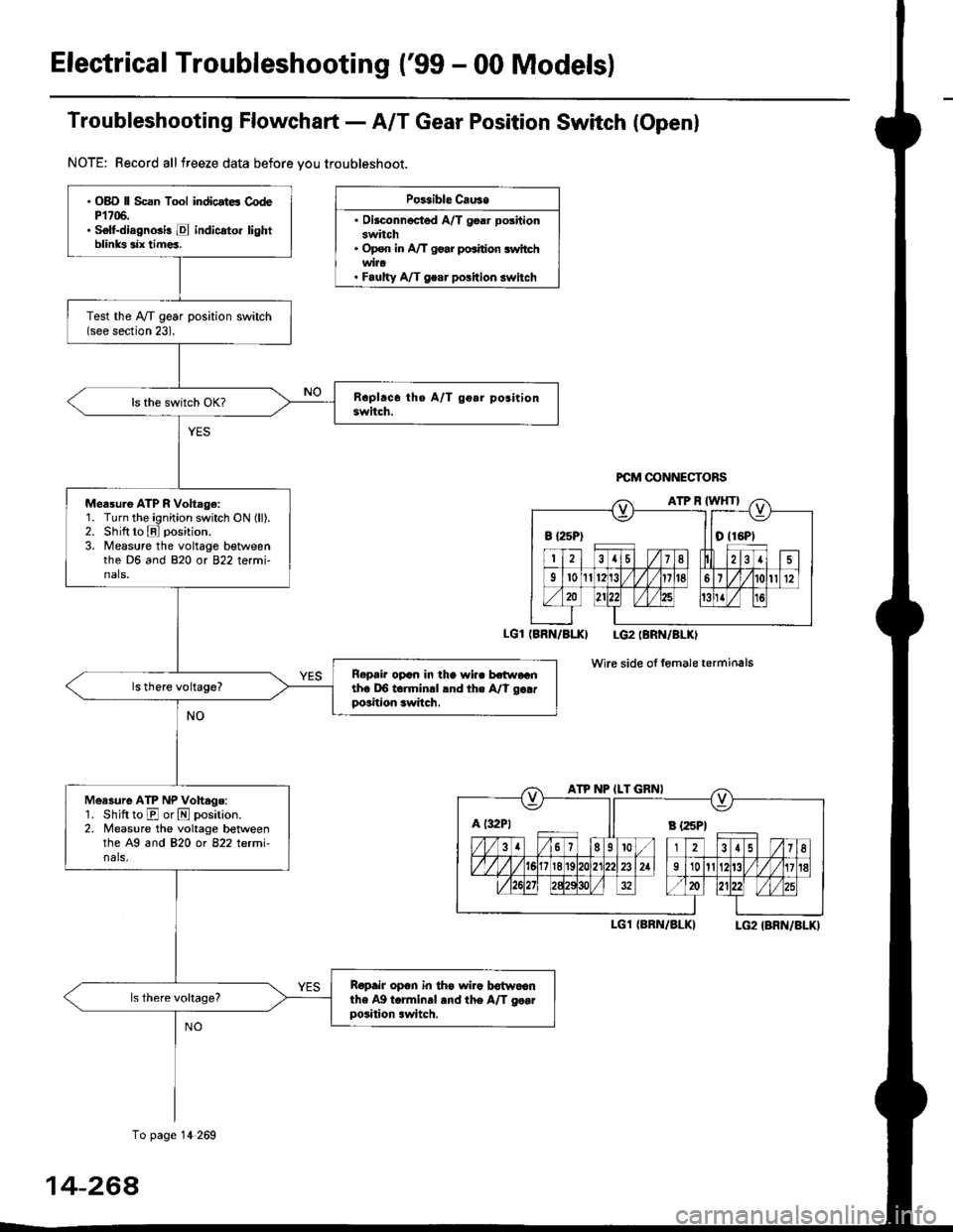
Troubfeshooting Flowchaft- AIT Gear Position Switch (Openl
NOTE: Record allfreeze data before vou troubleshoot.
Po$ible Cau3e
. Oilconnected A/T goar positionswitch. Op€n in A/T go.r po.ition switchwi?o. Faulty A/T gear polition switch
PCM @NNECTORS
(BRN/BI.XI LG2IBRN/BLKI
wire side of fomale terminals
I-G1 (BRN/BLKILG2 {BRN/BLK)
B {25P) I tO (16P1
ATP NP ILT GRNI
A t:r2Pt Il s tzspt
. OBD ll Scan Tool indicstE CodeP1706.. Selt-diagnGi! E indicato. lightblinks six tim€a.
Test the IVT gear position switch(see section 23).
Measu.e ATP R Voltage:1. Turn the ignition switch ON (ll).2. Shift to E position.
3. Measure the voltage betweenthe D6 and 820 or 822 termi-nals,
Ropair opcn in the wi.. hr.raGnth6 DO torminrl lnd the A/t g..rposition awitch.
Measure ATP NP Vohage:'1. Shift to E or N position.2. Measure the voltage betweenthe A9 and 820 ot 822 letmi-nals,
Ropair op6n in th€ wiro b€{woanthe Ag t.rminal and the A/T go..position .witch.
To page 14 269
14-264
Page 948 of 2189

JTroubleshooting Flowchart - Shift Control Linear Solenoid
NOTE: Record all freeze data before you troubleshoot
Possiblc Cause
. Disconn€cted solenoid harnos3
connectol. Short or oDen in shilt controllinetr solonoid wiro. Faulty shift control linear sole_
noid. Op€n in VB SOL wite. ODen in PG'l and PG2 wires or
poor ground {G10'l)
f,
wire side ot female terminals
LG1 IBRN/BLKILG2IBRN/BLK)
{cont'd)
14-271
PCM CONNECTORS
B(25P) - Dll6P)
.OBD ll Scan Tool indicatos
Code P1870.. Solf-diagnosis E indic.lor light
indic.t€s Code 30.
M6a3ure VB SOL voltage:1. Turn the ignition switch OFF.
2. Disconnect the B 125P) and D(16P) connectors from the
PCM,3. Turn the ignition switch ON (ll).
4. Measure the voltage between
the D5 and 820 or 822 terminals.
Repair open or shod in the wire
between the D5 terminal and the
under-dash tuso/telay box.
Check the Ground Circuitl1. Turn the ignition switch OFF.2. Check lor continuity between
the terminafs 82 and 822 and
between terminals 810 and
820.
Repair open in the wi.e betwoen
the termin.ls 82, B10, B20, and
822 and G101. Repair Poolground (G101).
LG1 IBRN/BLKI
PCM CONNECTOR B PsPI
PG,I IBLK)
10 page 14-272
a
Page 952 of 2189

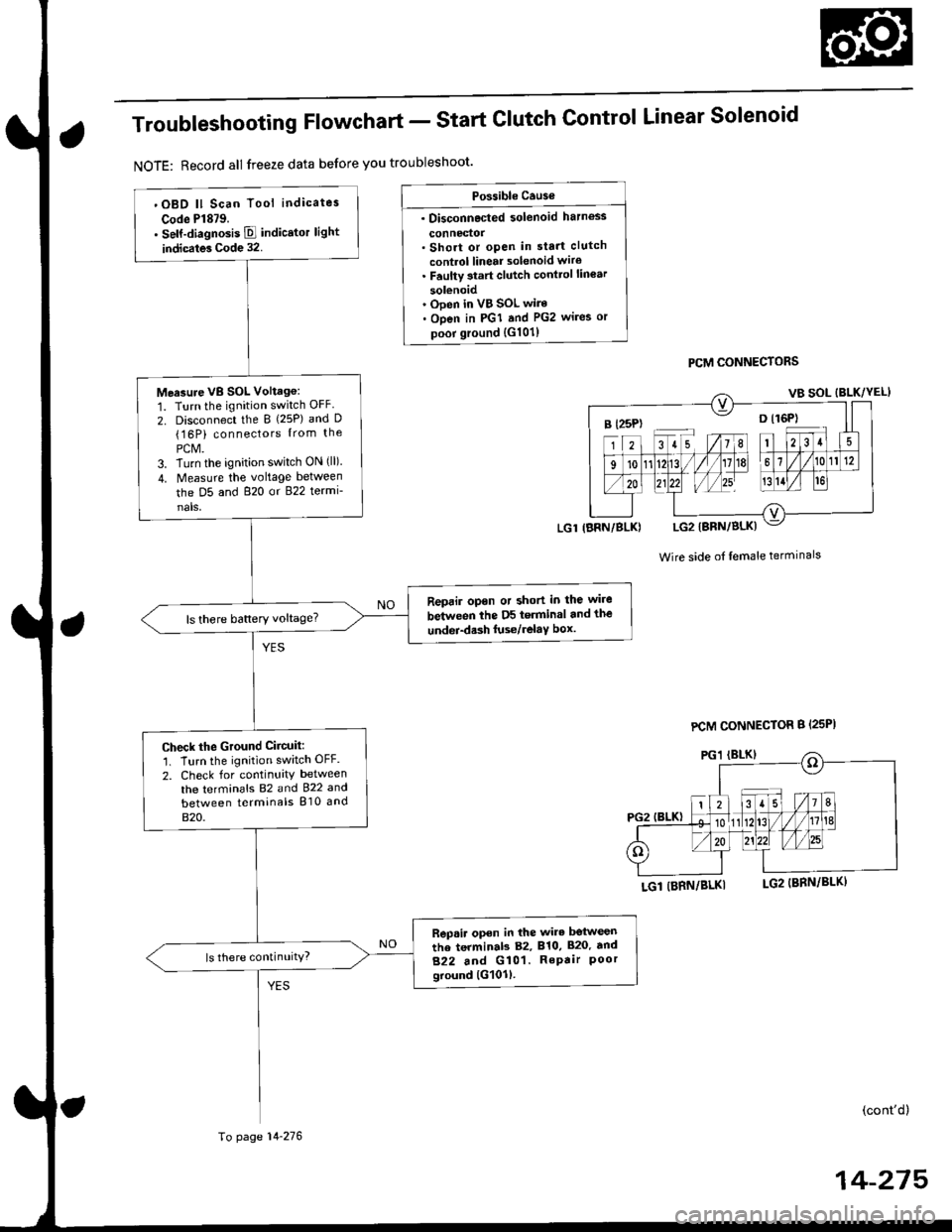
Troubleshooting Flowchart - Start
NOTE: Record all freeze data before you troubleshoot'
Clutch Control Linear Solenoid
PCM CONNECTORS
Wire side of lemale terminals
LGl (BRN/BLKI
(cont'd)
14-215
Po$ible Cause
. Disconnected solenoid harness
connedol. Short or open in sta.t clutch
control linear solenoid wiro. Faulty 3tart clutch conttol lin€ar
solenoid' Ooen in VB SOL wire. Open in PGI and PG2 wires or
poor ground {G101)
B l25P) -- o l16P)
'OBD ll Scan Tool indicates
Code Pl879.. self-diagnosis E indicstor light
indicates Code 32.
Measure VB SOL Voltag6:
1. Turn the ignition switch OFF
2. Disconnect the B {25P) and D(16P) connectors {rom the
PCM.3. Turn the ignition switch ON (ll).
4. Measure the voltage between
the D5 and 820 or 822 termi-
nals,
Reprir opon or short in the wire
between the D5 terminal and the
undei-d.sh luse/relaY box.ls there battery voltage?
Check the Ground Ciicuit:'1. Turn the ignition switch OFF.
2. Check for continuity between
the terminafs 82 and 922 and
between terminals 810 and
820.
Rep.ir open in the wire betwesn
the terminab 82, 810, 820. tnd
822 and G101. RePair Poorground lG101l.
ls there continuity?
LGl IBRN/BLK)
To page 14-276
PCM CONNECTOR B {25PI
Page 954 of 2189

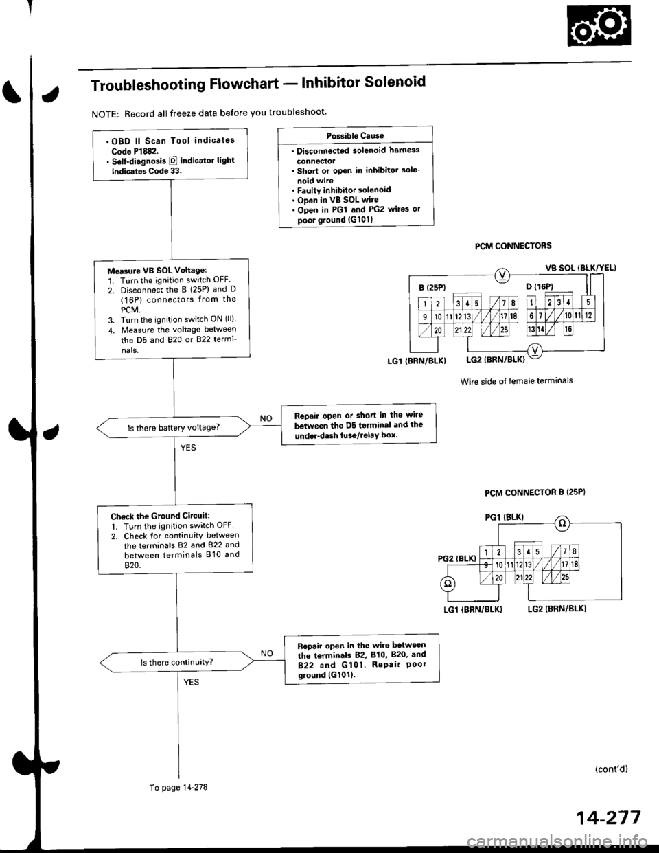
Troubleshooting Flowchart - lnhibitor Solenoid
NOTE: Record all freeze data before you troubleshoot'
Po3sible Cause
. Oi3connec'ted solenoid harn6s
connectoa. Shorl or open in inhibitor 3ole-
noid wir€. Faulty inhibitor solenoid. ODen in vB SOL wire. Open in PGl and PG2 wires or
poor ground {G101}
PCM CONNECTORS
Wire side ot female terminals
LGl IBRN/BLKILG2 (BRN/BLKI
(cont'd)
14-217
.OBD ll Scan Tool indicaies
Codo P'l882.. Self-diagnosis E indicttor light
indic.tes Code 33.
Me'sure VB SOL voltagel'1. Turn the ignition switch OFF.
2. Disconnect the B (25P) and D(16P) connectors from the
PCM.3. Turn the ignition switch ON (ll)
4. Measu.e the voltage between
the D5 and 820 or B22 termi-
nals.
Repair open or short in the wire
between the D5 tolminal and the
undor-dash lu36/relay box.ls there baftery voltage?
Ch€ck the Ground Circuit:
1. Turn the ignition switch OFF.
2. Check tor continuity between
the terminals 82 and 822 and
between terminals B'10 and
820.
R€pair open in the wire between
the torminal3 82, 810, B20, and
B22.nd G 101. RePair Poorground {G101).
(BRN/BLKI
To page 14-278
PCM CONNECTOR B {25P}