1999 HONDA CIVIC Fault code
[x] Cancel search: Fault codePage 777 of 2189

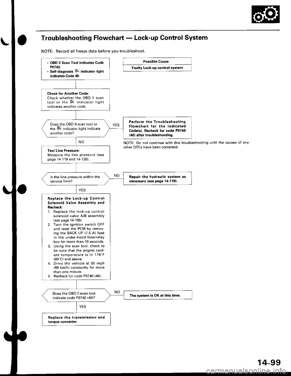
Troubleshooting Flowchart - Lock-up Control System
NOTE: Record all freeze data before vou troubleshoot.
Possibl€ Cause
Faulty Lock-up control sy3tem
NOTE: Do not continue with this troubleshootingother DTCS have been corrected.until the causes of any
OBD ll Scan Tool indicates Codem14/J.S€lf-diagnosis .D4l indicalor lightindicates Code 40.
Check for Another Code:Check whether the OBD ll scantool or the :E indicator lightindicates another code,
Perform the TroubleshootingFlowchart tor the indicatedCodels|. Rocheck to. code P0740(40) .fter troublBhooting.
ooes the OBD ll scan tool orrhe E indicator light indicateanother code?
Test Line Pressure:Measure the line pressure (see
page 14 119 and 14-120).
Repair the hydrrulic sy3tem asn6c6ssary (see page 14-1191.ls the lane pressure within theservice limit?
Replace the Lock-up ControlSolenoid Valve Assembly andRecheck:1. Replace the lock-up controlsolenoid valve A/B assembly(see page 14-105).2. Turn the ignition switch OFFand reset the PCM by removing the EACK UP (7.5 A) fusein the underhood {use/relaybox for more than 10 seconds.3. Using the scan tool, check tobe sure that the engine cool-ant temperature is in 176'F(80'C) and above.4. Drive the vehicle at 55 mph(88 km/h) constantly for morethan one minute,5. Recheck for code P0740 {40).
Does the OBD ll scan toolindicate code P0740 (40)?The svstem i3 OK .t this time.
14-99
Page 920 of 2189

Troubleshooting Flowchart - Vehicle Speed Sensor (VSS)
NOTE: Record all freeze data before you troubleshoot'
Po$rible Ctuse
. Disconnected vehicle speed
sensor (VSS) connectol. Short or open in VSS wire' Faulty VSS
@. Make sure lifts, iacks, and sal€tY stands are placed properly lsoe section 1)'
. Set the parking brake securelv, and block the rear wheels'
. iacr upile rront or the vehicle, and support it with safety st'nds'
TCM CONNECTORS
Wire side of female terminals
. OBD ll Scan Tool indicates Code
P1791.. Setf-diagno3is E indicato. light
blinks tour times.
Refer to seclion 23 for vehicle
soeed sensor IVSSI test
Check the VSS Voltage:
1. Raise the vehicle2. Shift the transmission to lEposrtlon.3. Disconnect the A (26P) and B(22P) connectors from the
TCM.4. Turn the ignition switch ON {ll).
5. Rotate the front wheel and
check for the voltage between
the 85 and 413 or A26 termi-
nals. Block the other wheel so
at does not turn
Check for oP€n in the wire
between the 85 terminal and the
vehicle speed sensor {VSS}. lf
wire is OK, check the vSS (see
soction 23).
Does0Vandapprox 5 V or more
appear alternatelY?
Check for loos€ TCM connedors
lI nec€ssary, substitute a known'
good TCM and recheck.
14-243
Page 921 of 2189

Electrical Troubleshooting ('96 - 9g Models)
Troubleshooting Flowchart - A/T Gear position Switch (Short)
NOTE: Record all freeze data before you troubleshoot.
Posrible Cause
. Short in A/T go.r positionswitch wire. Faulty A/T g€ar polition switch
NOTE: Code P1705(5) is caused whenthe TCM receives two gear positionInputs at the same time.
TCM CONNECTOR A {26P}
Wire side of female terminals
To page 14-245
. OBD ll Scan Tool indicates CodeP1705.. Seif-diagnosis @ indicator lightblinksfive times.
Obsorve the A/T gear positionindicetor:1. Turn the ignition switch ON1[).2. Observe tho Ay'T gear positionindicator, and shift to eachposition separately.
Th6 lyrtcm i3 OK at thi. tima.Check the wi.s hamels for drm.ag9.
Do any jndicators stay on when thesh;ft lever is not in that position?
Measure ATP R Vohage:1. Shift to all positions other thanE.2. Measure the voltage betweenthe 411 and A13 or A26 termi-nats.
Check for sho.t in tho wireb€twoon the Al1 t rminaland th6A/l ge.r polhion switch or A/Tgear position indicstor. lf wilo isOK check for loos6 TCM conncc-tora. It nocassery, subrtitute aknown-good TCM and r€chsck.
ls there approx. 10 V?
Measure ATP NP Volt.ge:1. Shift to all positions otherthan @ or @.2. Measure the voltage betweenthe A10 and 413 or 426 termi-nals,Ch.ck tor 3hort in th€ wircb€twe€n thc Al0 termin.l andthe A/T 96r. porition indicrtor,or a short in the wilea b?twecntho A/T gerr porition indic.to.and the A/T geer positionswitch. It wires ar6 OK, chsck forloose TCM conn.clols. ll nccNe3-sa.y, substituto a known-goodTCM rnd locheck.
ls there approx. 10 V?
Measure ATP O Vohage:1. Shift to all positions otherthanE,2. Measure the voltage betweenthe Ag and A13 or 426 terminals.
Checl tor short in the wirelr€tweon tho A9 terminal and theA/T g6a. position 3witch. lf wireb OK. check tor loos€ TCM con-nectors. lf nocelsary, substhute aknown-good TCM and rechack.
ls there approx. '10 V?
14-244
b
Page 923 of 2189

Electrical Troubleshooting (,96 - 9g Models)
Troubleshooting Flowchart - A/T Gear position Switch (Openf
NOTE: Record all freeze data before you troubleshoot.
Pos.ribls Cause
. Disconnocted A/T gear positionswitch connector. Open in A/T gear position switch
. Faulty A/T gear position switch
TCM CONNECTOR A I26PI
Wire side of female terminals
. OBD ll Scan Toot indicat* CodeP1706,. Solf-diagnosis E indicator tightblinb six times.
Measule ATP R Volt.gei1. Turn the ignition switch ON l).2. Shifi to E position.3. Measure the voltage betweenthe A11 and 413 or ,426 termi-nals.
Repair open in tho wire betwoenlhe A11 terminal and the A/Tgoar po3ition switch.
Measure ATP NP Volt.gei1. Shifrto E orE position.2. Measure the voltage betlveenthe A10 and A13 or 426 terminals.
Repair open in the wiro betweenthe A10 terminal .nd tho A/Tgea. poshion swhch.
Measure ATP D Vohage:1. Shift to E position.2. Measure the voltage betweenthe Ag and A'13 or 426 termi-
Repair open in the wire lretweenthe A9 terminel and the A/T gearposition 3witch.
To page 14-Z4j
14-246
Page 927 of 2189

Electrical Troubleshooting (,96 - 9g Modelsl
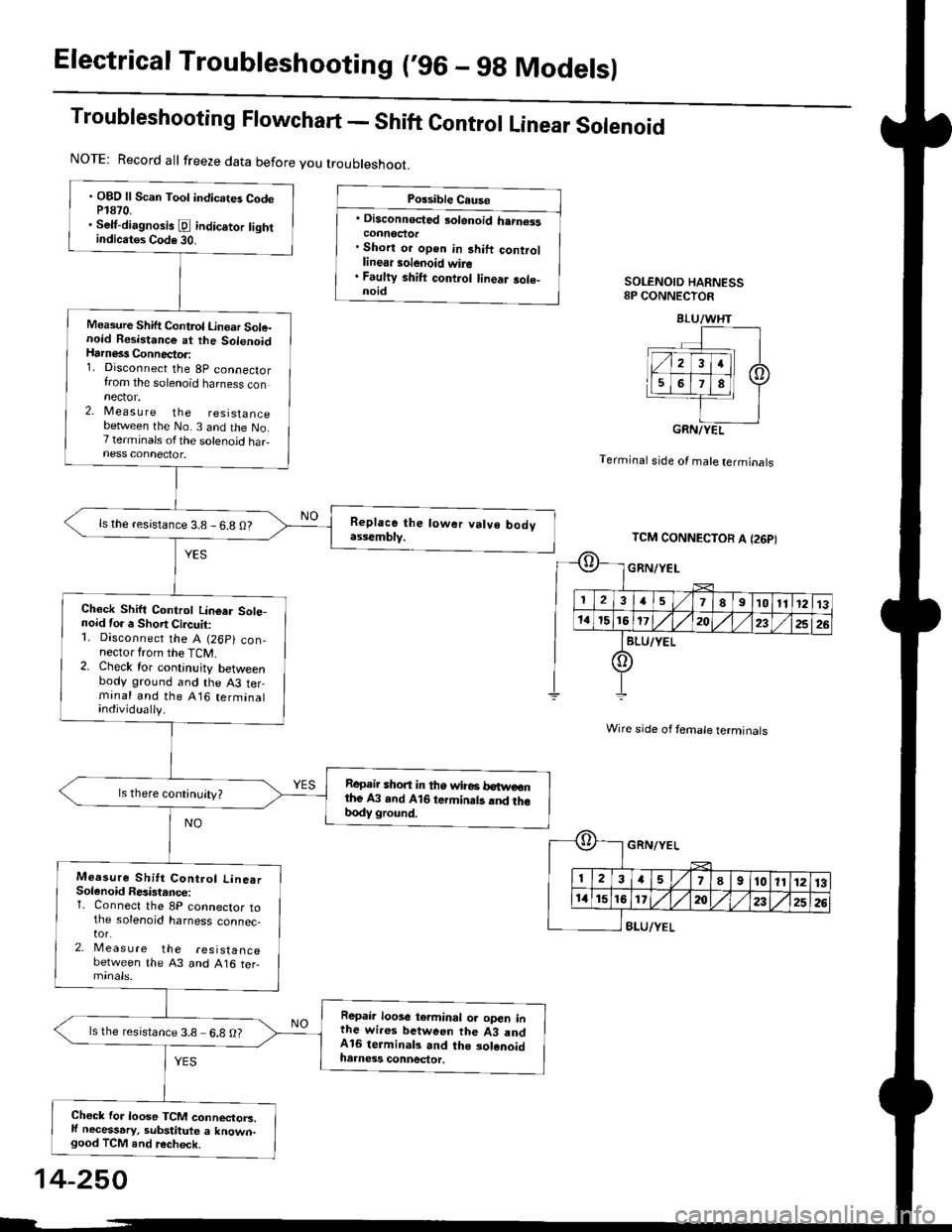
Troubleshooting Flowchart - Shift Control Linear Solenoid
Possible Cause
' Disconnected 3olenoid h.rn€isconnoctor. Short or open in 3hift controllinear solenoid wire. Faulty shift control linear sole-noidSOLENOID HARNESS8P CONNECTOR
Terminal stde of male terminals
Wire side of female terminals
8LU/YEL
NOTE: Record all freeze data before you troubleshoot.
. OBD ll Scan Toot indicates CodeP1870.. Selt-dirgnosis [d indic.tor tightindicatos Code 30.
Measure Shift Control Linoar Sole-noid Resistance at the SolenoidHarness Connector:1. Disconnect the 8p connectorfrom the solenoid harness connector.2, Measu re the resistancebetlveen the No. 3 and the No.7 terminals ofthe solenoid haFness connector.
ls the resistance 3.8 - 6.8 O?
Check Shift Controt Linear Sote-noid for a Short Circuit:1. Disconnect the A (26p) con,nector from the TCM.2. Check for continuity betweenbody ground and the A3 terminal and the A16 terminalindividually.
Repair shon in tho wire6 betweonthe A3 and A16 termin.ts lnd thobody ground.
Measure Shitt Control Line.rSolenoid Resistance:1. Connect the 8P connector tothe solenoid harness connec,tor.2, Meas u re the resistancebetween the 43 and A16 ter-
Repair loose terminal oa open inthe wires between the 43 andA16 terminal3 and the solenoidharness connector.
ls the resistance 3.8 6.8 O?
Chock for loose TCM connectorc.ll necessary, substitute a known-good TCM and recheck.
BLU/WHT
GRN/YEL
TCM CONNECTOR A I26PI
GRN/YEL
ll 12l:
IriGlx
1578910111213
172t)232526
14-250
Page 928 of 2189

Troub|eshootingF|owchart_PH-PLControJLinearSo|enoid
NOTE| Record all treeze data before you troubleshoot
Possible cause
' Disconnected solenoid harness
connectof. Short or oPen in PH_PL control
linear solenoid wire. Faulty PH-PL control linear sole_
noidSOLENOIO HARNESS8P CONNECTOR
GRN/WHT
Terminal side of male termlnals
Wire side ol female terminals
. OBD ll Scan Tool indicates Codo
P1873.. sef-diagnosis E indicalor light
indicat6 Code 31.
Measure PH-PL Control Linear
Solenoid Resistance at the Sole_
noid Hatness Connectot:1. Disconnect the 8P connector
from the solenoid harness con-
nector,2. Measure the resistance
between the No 2 and the No.
6 terminals ofthe solenoid har
ness connector'
ls the resistance 3.8 - 6.8 0?
Check PH-PL Control Lineer
Solenoid for a Short Circuit:
1. Disconnect the A 126P) con-
nector lrom the TCM
2. Check for continuity between
body ground and the A2 ter
minal and the A15 terminal
individually.
Repair short in th€ wires
between the A2 and A15 lermi_
nals and the body glound.
Measute PH-PL Control Linear
Solenoid Resi3tance:1. Connect the 8P connector to
the solenoid harness connec-
tor,2, Meas u re the reslslance
between the ,q2 and A15 ter_
Rep.il loose tetminal or oPen in
th6 wires betwccn the A2 and
A15 lerminals and the solenoid
harness conn€ctol.
lsthe resistance 3.8-6 8 O?
Check for loose TCM connactors
lf neceasery, Substitute a known-good TCM and rechock.
PNK/BLK
TCM CONNECTOR A (26P)
oPNK/BLK
I234578I10l11213
11't5161720/,,/232526
IGRN/wHr
o
*r}l
t'T,
E[
PNK/8LK
3a5I910111213
1620232526
GRN/WHT
14-251
Page 929 of 2189

Electrical Troubleshooting ('96 - gg Modelsl
Troubleshooting Flowchart - start clutch control Linear solenoid
NOTE: Record all freeze data before you t.oubleshoot.
Po$iblo C.u.o
' Di3aonnoctod solanoid harncatconnactol. Short or opon in start clutchcontrol linoar tolanoid wira. Faulty ttart clutch control lino.rsolanoid
SOLENOID HARNESS8P CONNECTOR
Terminal side of male terminals
Wire side of female terminals
. OBO ll Scan Tool indicatG CodeP1879.. Self-dilgno.is E indicator lightindiclt$ Code 32.
Me.suro Sta.t Clutch ControlLinear Solenoid Rosirtrnco st th.Solenoid Hrrn6rs Connecto.:1. Disconnect the 8P connectorfrom the solenoid harness con-nector.2, Measure the resistancebetween the No. 4 and the No.8 terminals otthe solenoid har-ness connectot.
ls the resistance 3.8 - 6.8 0?
Chock Start Clutch Control Lin-oar Solenoid tor a Short Circuit:1. Disconnect the A (26p) con,nector from the TcM.2. Check lor continuity betweenbody ground and the A1 ter-rninal and lhe Al il terminalindividually.
Raprir 3hort in tha wira3b.ftvcen tho A1 .nd Atil t .mi.n.l. .nd thr body ground.
Measure Stan Clutch Cont.olLineer Solenoid F6aist.ncei1. Connect the 8P connector tothe solenoid harness connec-tor.2. Meas u re the resistancebetween the 41 and Al4 ter-minals,
Rcplir loose tcrminal or oDcn inthG wiras b.tween the Al rndAla torminal3 rnd tha 3olanoidhamaas connactor.
ls the resistance 3.8- 6.8 O?
Check for loose TCM connecto.s.lf necessary, substitute a known-good TCM and iecheck.
YEL
PNK/BLU
TCM CONNECTOR A I26P}
-{r-
E
PNK/BLU
23a51I910ll1213
a15t61'20a252G
YEL
14-252
Page 930 of 2189

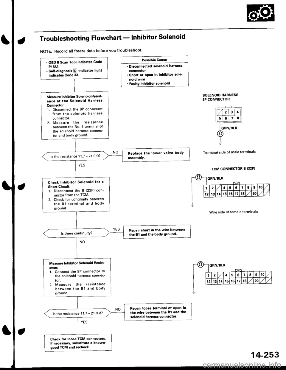
Troubleshooting Flowchart - Inhibitor Solenoid
NOTE: Record all treeze data betore you troubleshoot
Po$ibls Cause
. Dbconnected solenoid hatness
connedor' Short or opon in inhibitor sole'
noid wire. Faultv inhibitor solenoid
SOLENOID HARNESS8P CONNECTOR
Terminal side of male terminals
. OBD ll Scan Tool indic.td Code
P1882.. Selt-di.gnGis E indicator lighl
indic.tos Code 33.
Mea3ure Inhibhor Solenoid Resid-
ance at the sol€noid Harness
Connector:1. Disconnect the 8P connector
from the solenoid harness
connector.2. Measure the reslstance
betlveen the No 5 terminal of
the solenoid harness connec-
tor and body ground.
ls the resistance 11.7 - 21 0 0?
Check Inhibitor Solenoid lor a
Short Circuii:1. Disconnect the B (22P) con-
nector from the TCM.
2. Check for continuity between
the B1 terminal and bodygro!no.
Repair rhort in the wire ltetwegn
the 81 dnd the bodY ground.
Mea$rr€ Inhibitor Solenoid ResBt'
anoe:1. Connect the 8P connector to
the solenoid harness connec_
IOr.2. Measure the resistance
between the Bl and bodyground.
Reoair loose terminal or open in
the wire betwean the 81 and the
solenoid hame3s connector'ls the resistance 11.7 - 21.0 O?
Ch6ck for loose TCM connectors.
ll necessary, substhule a known_good TCM and techeck.
Wire side of female terminals
14-253