Page 355 of 2189

Troubleshooting
Troubleshooting Procedures (cont,dl
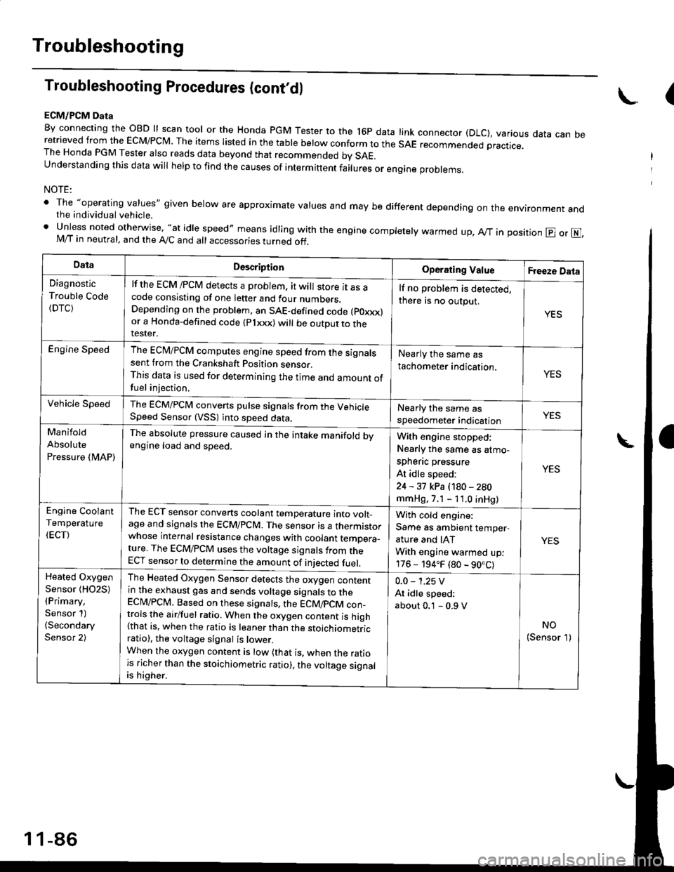
ECM/PCM Data
By connecting the OBD ll scan tool or the Honda pGM Tester to the l6p data link connector (DLC), various data can beretrieved from the EcM/PcM. The items Iisted in the table below conform to the sAE recommended practice.The Honda PGM Tester also reads data beyond that recommended bv SAE.understanding this data wil help to find the causes of intermittent fairures or engine probrems,
NOTE:
' The "operating values" given below are approximate values and may be different depending on the environment andthe individual vehicle.. Unless noted otherwise, "at idle speed,, means idling with the engine completely warmed up, Ay'T in position @ or E],M/T in neutral, and the Ay'C and all accessories turned off.
(
DataDescriptionOperating ValueFreeze Data
Diagnostic
Trouble Code(DTC)
lf the ECM /PCM detects a problem, it will store it as acode consisting of one letter and four numbers.Depending on the problem, an SAE-defined code (poxxx)or a Honda-defined code (Plxxx) will be outDut to therester.
lf no problem is detected,
there is no output.
YES
Engine SpeedThe ECM/PCM computes engine speed from the signalssent from the Crankshaft Position sensor.This data is used for determining the time and amount offuel injection,
Nearly the same as
tachometer indication.YES
Vehicle SpeedThe ECM/PCM converts pulse signals from the VehicleSpeed Sensor (VSS) into speed data.Nearly the same as
speedometer indicationYES
Manifold
Absolute
Pressure {MAP)
The absolute pressure caused in the intake manifold bvengine load and speed.With engine stopped:
Nearly the same as atmo-
spheflc pressure
At idle speed:
24 - 31 kPa (180 - 280
mmHg, 7.1 - 11.0 inHg)
YES
Engine Coolant
Temperature
(ECT)
The ECT sensor converts coolant temperature into volt_age and signals the ECM/PCM. The sensor is a thermistorwhose internal resistance changes with coolant temDera_ture. The ECM/PCM uses the voltage signals from theECT sensor to determine the amount of iniected fuel.
With cold engine:
Same as ambient temper,
ature and IAT
With engine warmed up:
176 - 194.F (80 - 90.C)
YES
Heated Oxygen
Sensor {HO2S)(Primary,
Sensor 1)(Secondary
Sensor 2)
The Heated Oxygen Sensor detects the oxygen contentin the exhaust gas and sends voltage signals to theECI\4/PCM. Based on these signats, the ECM/pCM con_trols the airlfuel ratio. When the oxygen content is high(that is, when the ratio is leaner than the stoichiometricratio), the voltage signal is lower.When the oxygen content is low (that is, when the ratiois richer than the stoichiometric ratio), the voltage signalis higher.
0.0 - 1.25 V
At idle speed:
about 0.1 - 0.9 V
NO(Sensor 1)
1 1-86
Page 610 of 2189
Differential
Check lor cracks.
BALL BEARINGCheck for wear and damage.
DIFFERENTIAL
THRUST SHIMSelective part
SPEEDOMETERDRIVE GEAR
10 x 1.0 mm101 N.m (10.3 ksf.m. 74.5 lbt.ftlLeft-hand threads
ffi
FrNAL DRTvEN o*^r'@c'ec'owea'�-Zl
BALL BEARINGCheck for wear and damage.
13-30
Backlash Inspection
'1. Place differential assembly on V-blocks, and installboth driveshafts.
OIAL
Measure backlash of both pinion gears.
Standard {New); 0.05 - 0.15 mm {0.002 - 0.006 in)
lf the backlash is not within the standard, reDlacethe differential carrier.
SI
Page 844 of 2189
Differential
lllustrated lndex
BOLT10 r 1.0 mm'10'l N'm (10.3 k91.m,74.5 lbf.ftlLeft-hand threads
SET RING, 80 mrrt
FINAL DRIVEN GEARInspect tor excessive wear.Install in this direction.
efef
BALL BEARINGInspect for faulty movement.
DIFFERENTIAL CARRIERInsoect for cracks,
ROLLER,5x10mmSPEEDOMETER ORIVE
GEARlnstall in this direction.
SNAP RINGInstall in this direction.
EALL BEARINGInspect for faulty movement-
-
14-166
Page 846 of 2189

Differential
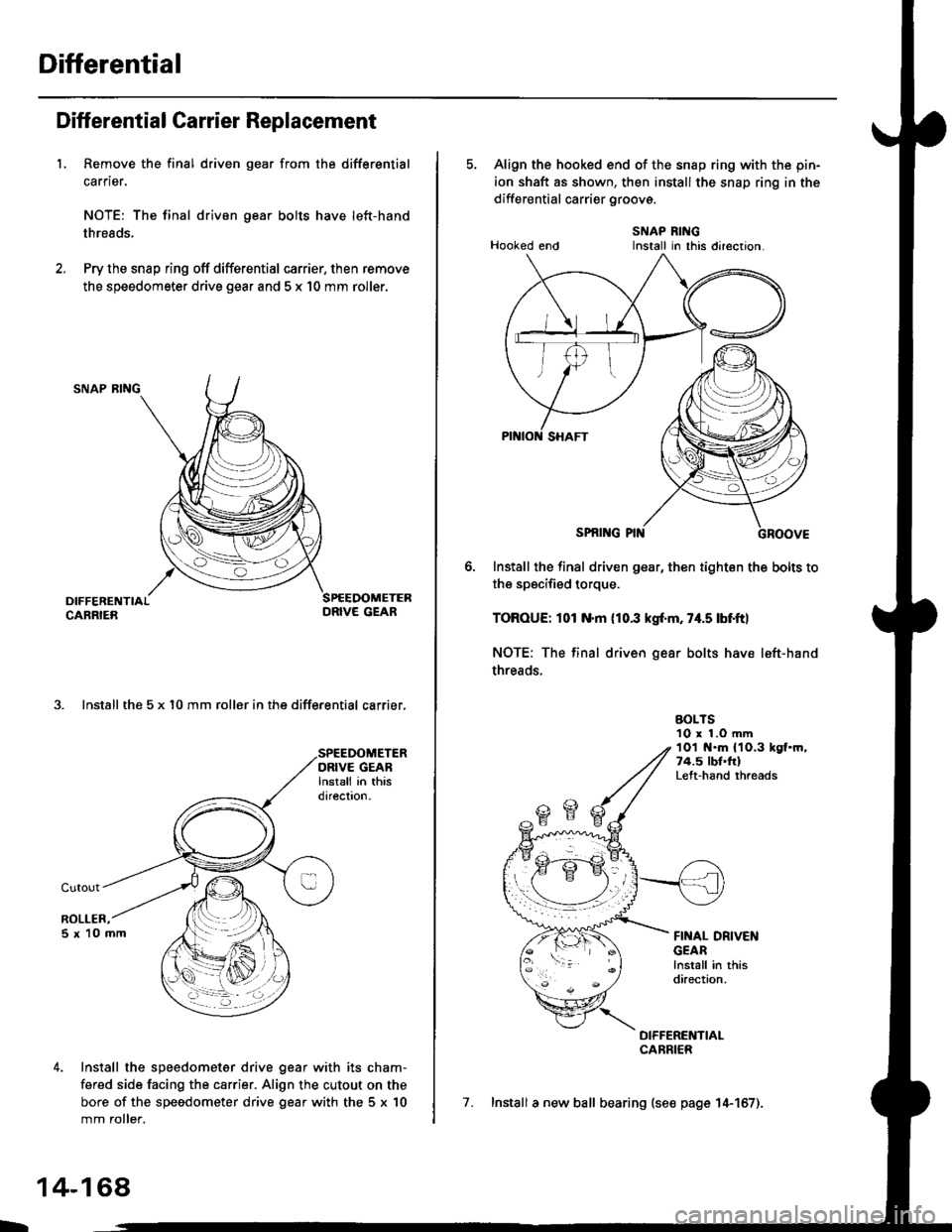
Diff erential Carrier Replacement
L Remove the final driven gear from the differential
carrier.
NOTE: The final driven gear bolts have left-hand
threads.
Pry the snap ring off differential carrier, then remove
the speedometer drive gear and 5 x 10 mm roller.
SNAP RING
3. Install the 5 x l0 mm roller in the differential carrier,
Install the speedometer drive gear with its cham-
fered side facing the carrier. Align the cutout on the
bore of the speedometer drive gear with the 5 x 10
mm roller.
L
14-168,
5. Align the hooked end of the snap ring with the pin-
ion shaft as shown, then install the snap ring in the
differential carrier groovs.
SNAP RINGHooked end Install in this direction.
SPNI G PIN
Install the final driven gear, then tighten the bolts to
the specified torque.
TOROUE: 101 N.m (10.3 kgf'm, 74.5 lbf.ftl
NOTE: The final driven gear bolts have left-hand
threads.
BOLTS10 r 1.O mm1Ol t{.m 11O.3 kgf.m,74.5 lbl.frlLeft-hand rhreads
FINAL DRIVENGEARlnstall in thisdirection.
DIFFERENTIALCARRIER
7. Install a new ball bearing (se€ page 14-157).
Install in this direclon.
Page 893 of 2189
E position, at middle sPeed range
Asthespeedofthevehic|ereachestheprescribedVa|ue,theshiftcontro||inearsolenoidisactivatedbytheTcMorPcM'
Theshiftcontro||inearso|enorocontroIsttresniftcontroIVa|vetoactivateshiftVa|vepressure(SV)'c|utchreducingpres-
sure (CR) trom the clutch reduclng valve becomes shift valve pressure (SV) at the shift control valve Shift valve pressure
(SV)flowstothe|eft"noottr'"st'ittu"tue.theshiftVa|Vetotherightsideandpositioningitinthemidd|eofitstrave|.The
shift valve covers th" pon ao ",oo nLior".irr" tiHl a ,tr" pulleys, and uncovers the port leading low pressure (PL) to the
pu eys. The drive pu ey and tne oriJen priLy |."""iu" to* pressure (PL). At this time, the pulley ratio is in the middle'
Pressure remains to apply the forward clutch and the start clutch'
NOTE: When used, "|eft" or "right" indicates direction on the hydraulic circuit'
(cont'd)
14-215
Page 982 of 2189
I
6. Disconnect the vehicle speed sensor (VSS) connec-
tor, the driven pulley speed sensor connector, and
the secondary gear shaft speed sensor connector.
SECONDARY GEARSHAFT SPEEDORIVEN PULLEY
SPEED SENSORCONNECTORSENSOR
7. Remove the transmission housing mounting bolts.
14-305
8. Remove the drain plug, and drain th€ CVT fluid
Reinstall the drain plug with a new sealing washer.
CAUTION: While installing the drain plug' bo 3ur.
nol io allow du3l 8nd other toreign particles to
enter into th€ trsnsmi$ion.
DRAIN PLUG18 x 1.5 rnm(, N.m (5.0 kgfm, 36 lbf'ft|
9. Remove the splash shield.
SEALING WASHERReplaco.
Page 1599 of 2189
JGau ge/lndicator/Terminal
With tachometer;
CONNECTOR "A"
{A/T GEAR POSITION INDICATOR}
Location lndex
CONNECTOR "8"
{GAUGE and INOICATOR)CONNECTOB "C"
CONNECTOR "D"
{ABS INDICATORI
SPEEDOMETER:Indicates 60 km/h at 637 rpm or
60 mph at 1,025 rpm o{thevehicle speed sensor (VSS).
A/T GEAR POSITIONINDICATORSee page 23 149
TACHOMETER:Indicates 100 rpm at200 pulses per minuteol the ignition controlmodule (lCMi.FUEL GAUGEENGINE COOLANT TEMPERATURE (ECT) GAUGE
(cont'd)
23-129
(GAUGE end INDICATORI
A1-----------+816
JlltlllulllllrL
c1 --------->c13
1ililil{ilrL
oooo o 0006^
)og @ @ o^o @ )'l |. o
Fl- - -> F5E1_ _ -->E5D1- --+05
oo/ \oo
Gauge/Sending Unit Test, page 23-142
Page 1600 of 2189
Gauge Assembly
Gauge/lndicator/Terminal Location Index (cont'd)
Without tachometer:
CONNECTOR "A"
IA/T GEAR POSITION INDICATORICONNECTOR "8"
{GAUGE and INDICATOR}CONNECTOR "C"
(GAUGE and INDICAIORI
CONNECTOR "F"
{SRS INDICATOR)CONNECTOR "D"
{ABS INDICATORI
SPEEDOMETER:Indicates 60 km/h at 637 rpm or60 mph at 1,025 rpm ofthevehicle speed sensor (VSS).
ENGINE COOLANT TEMPERATUFE (ECT) GAUGEA/T GEAR POSITIONINDICATOFSee page 23 149FUEL
A1 ------> 46
----> al4
B1. - --------------->B16
JilililHililil1
C1-- - --------..+C13
JililHililL
Oo_o-o O 0006
lus 0 0 Bu-. )
oo/ \oo
23-130
Gauge/Sending Unit Test, page 23 142