Page 1705 of 2189
Moonroof
a-/
Component Location Index
MOONBOOF SWITCHTest, page 23-236
. MOONROOF CLOSE RELAYlwire colors: WHT. GRN/YEL, lIGRN/oBN, BLK, and GRN/REDITest, page 23 87, 88. MOONROOF OPEN RELAY
f wire colors: WHT, cRN/RED,l
IGBN/ORN, BLK and YEL lTest, page 23'87, 88
MOONROOF MOTORTest, page 23-236
l-,
23-235
Page 1819 of 2189
How To Use This Manual
Circuit Schematics
oa
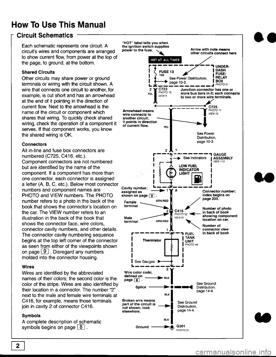
Each schematic represents one circult. A
circuit's wires and components are arranged
to show current flow, from power at the top of
the page, to ground, at the bottom.
Shared Circuits
Other circuits may share power or ground
terminals or wiring with the circuit shown. A
wire that connects one circuit to another, for
example, is cut short and has an arrowhead
at the end of it pointing in the direction of
current flow. Nelit to the anowhead is the
name o{ the circuil or comoonent which
shares that wiring. To quickly check shared
wiring, check the operation of a component it
serves. lf that component works, you know
the shared wiring is OK.
Connectors
All in-line and fuse box connectors are
numbered (C725, C416, etc.).
Component connectors are not numbered
but are identiJied by the name of the
component. lf a componenl has more than
one connector, each connector is assigned
a letter (A, B, C, etc.). Below most connector
numbers and comDonent names are
PHOTO and VIEW numbers. The PHOTO
number refers to a Dhoto in the back of the
book that shows lhe conneclor's location on
the car. The VIEW number refers to an
illustration in the back of the book that
shows the connector face, wire colors,
connector cavity numbers, and other details.
The connector cavity numbering sequence
begins at the top left corner oJ the connector
as seen from either of the viewooints shown
on page ffl . Disregard any numbers
molded into the connector housino.
Wires
Wires are identilied by the abbreviated
names of their colors; the second color rs the
color of the stripe. Wires are also identified by
their location in a connector. The number '2"
next to the male and female wire terminals at
C416, for example, means those terminals
join in cavity 2 of connector C416.
Symbols
A complete description of schematic
symbols begins on page | 8
"HOT" label tells you whenthe ignition switch suppliespower to the fuse. \
Artowhead meanswire connects toanother circuit;
Arrow with note rErngother circuils conncct h€re.
it .a
llu":: ^,{ ii t See Power Distribution, .I t----t oaqe tO-3. IL*--:--------J2 Y C723 Junction connectorYEL I Pao'o'8 more bus bars in it;
I - " " to two or more wire
l,/
-t>?
See PowerDistribution,page 10-3.
UNDER.DASHFUSE/RELAYBOX
has one oleach connactgterminala.
it ooints in directionof current flow.
TheImletor
t_I
Cavity number; L ---
Jiili'iJi!--' -----> '
shoin on page S .
Maleterminal
L?*?l?,-
"'"'I
c725
vlEUt/ 75
Connector number;index begins onpage 203.
Number ot photoin back ol bookshowing componentlocation on cat.
Number ofconneclor viewin back of book
7
GBN/FEO
See Ground
Soe Indicators I ASSEMBLY
:-------J
LOW FUELINDICATOFLIGHT r-l
EI
A
"o'r"/PHOTO 52 <-
\
FUELTANKUNIT
Splice ---------) O rr
".* I Page 14'4'
IBroken wire means | --^ -
iar";J.'It,;,rJ;ii; -----i Bffi,Bili*l
elsewhere. I 0a0e tn-a
IBrK Icround --->lL c301: ptioro 21
Page 1824 of 2189
Connector Views
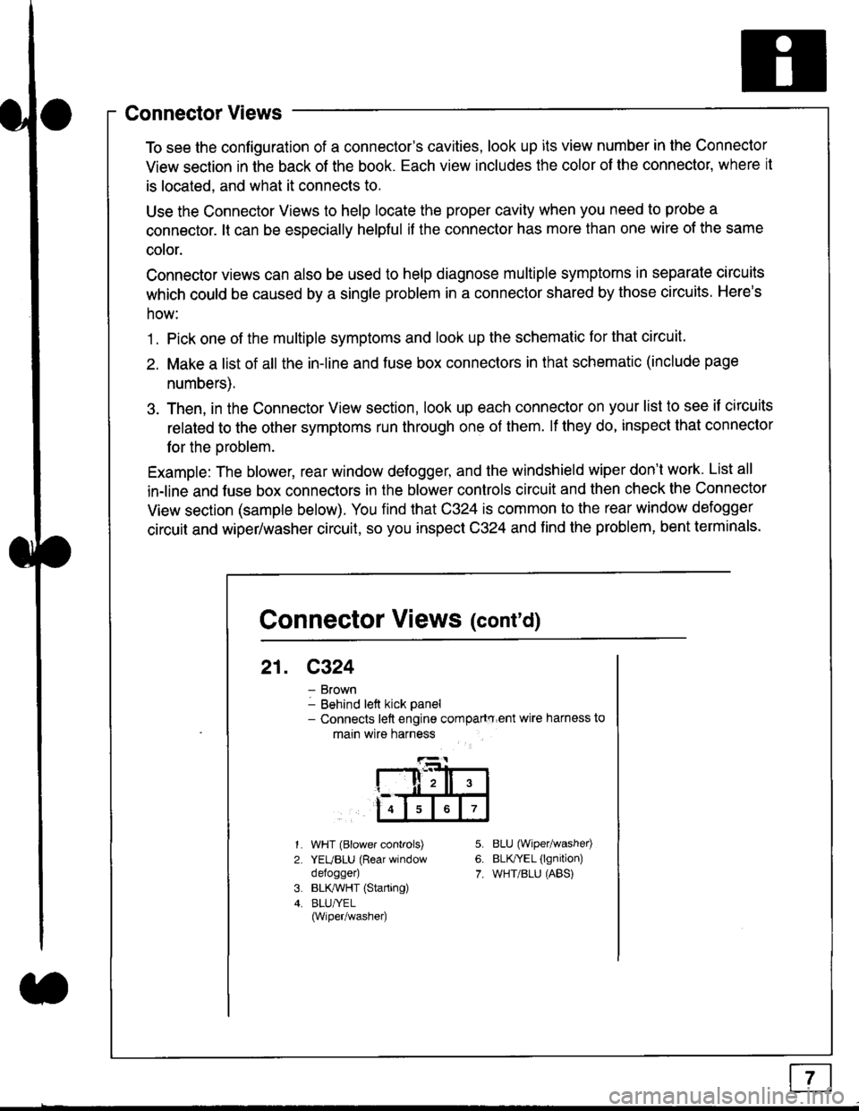
To see the configuration of a connector's cavities, look up its view number in the Connector
View section in the back of the book. Each view includes the color of the connector, where it
is located, and what it connects to.
Use the Connector Views to help locate the proper cavity when you need to probe a
connector. lt can be especially helpful if the connector has more than one wire of the same
cotor.
Connector views can also be used to help diagnose multiple symptoms in separate circuits
which could be caused by a single problem in a connector shared by those circuits. Here's
how:
1. Pick one of the multiple symptoms and look up the schematic for that circuit.
2. Make a list of all the in-line and fuse box connectors in that schematic (include page
numbers).
3. Then, in the Connector View section, look up each connector on your list to see il circuits
related to the other symptoms run through one of them. lf they do, inspect that connector
for the oroblem.
Example: The blower, rear window defogger, and the windshield wiper don't work. List all
in-line and fuse box connectors in the blower controls circuit and then check the Connector
View section (sample below). You find that C324 is common to the rear window defogger
circuit and wiper/washer circuit, so you inspect C324 and find the problem, bent terminals.
5.
6.
7.
1.
2.
WHT (Blower controls)
YEUBLU (Rear window
defogger)
BLK,ryVHT (Starting)
BLU/YEL(Wiper/washe0
8LU (Wiper/washed
BLfiEL (lgnition)
WHT/BLU (ABS)
Connector Views (cont'd)
21. C324
Brown
Behind left kick panel- Connects left engine compartry'ent wire harness to
main wire harness
ll,ll,
567
Page 1825 of 2189
How To Use This Manual
Symbols
oo
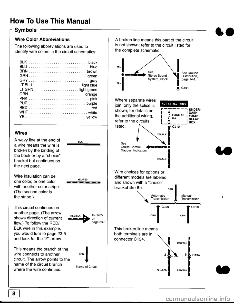
Wire Color Abbreviations
The following abbreviations are used to
identify wire colors in the circuit schematics:
BLK.... .........b|ack
BLU.... ......... blue
BRN.... ,....... brown
GRN.... ........ green
GRY.... ......,.. gray
LTBLU . .....lightbtue
LTGRN. ....lightgreen
ORN.... ....... orange
PNK .... .......,.. pink
PUR .... ........ purple
RED .... .......... red
WHT... .........white
YEL .... ........ yellow
A broken line means this part of the circuit
is not shown; refer to the circuit listed for
the complete schematic.
"ral
o
-.1
See GroundDistribution,page 141.
I G101
Where separate wires
join, only the splice is
shown; for details on
the additional wiring,
refer to the circuits
listed.ili::i
{[
UNDER-OASHFUSE/RELAYBOX
Wires
A wavy line at the end of
a wire means lhe wire is
broken by the binding of
the book or by a "choice"
bracket but continues on
the next page.
Wire insulation can be
one color, or one color
with another color stripe.
(The second color is
the stripe.)
This circuit continues on
another page. (The arrow
shows direction o{ current
flow.) To tollow the RED/
BLK wire in this example,
you would turn to page 23-5
and look for the "2" anow.
This means the branch of the
wire connects to another
circuit. The arrow Doints to the
name of the circuit branch
where the wire continues.
8LK-Cruise Control, €�aaaGauges, Indrcalors
!YEUsLK
Ttl
Wire choices for options or
different models are labeled
and shown with a "choice"
bracket like this.
This broken line means
both terminals are in
connector C134.
a.
+##l:i""lManuallransmission
ryil;::,
.""1
""'
"""1".'0
I
""^l
:-lName of Circuit
Page 1857 of 2189
Ground Distribution
- Gl01 (All '96-'98 models except D1685; '99100 D16y5 with M/T)
NOTE: Wires shown without color codes
:--- CVr --' D16y5/
i rnlts_ ' ._ 016y8,MISSION',englnes
: CONTROL ' PGM.FI :: MODULE i UAIH ; VTEC, TTCM) ; RELAY . PRESSURE' Paae 39-5 ' Paoe 23 ' SWITCHI pHdro et ' n 6roao ' Page 23-4I vtEw 69 | vtEw 1a ' pHoro 44' r---.t ' r-1 I i-r
POWERTRAIN orENGINE CONTROLMODULE (PCM or ECM)Page 23-3PHATO 86vlEw 7a; r---1 ;r-1 , r, I t,t | ,l
: I t:t | :l, L---J, L-J ' L-, A26Y A13Y , 3,2
i T T: I I
I I, I t,,-I T T: T i
: I t:--I-. :
i I \li:; -4, ;!-------------l-i '
'lF;% :21 ,vlEw 28 ;
_ - t\4/T -
PRIMARYHEATEDOXYGENSENSOR(H02S)Page 23-13
ll
tl
"i[",..
14
o---1\
I
Page 1859 of 2189
Ground Distribution
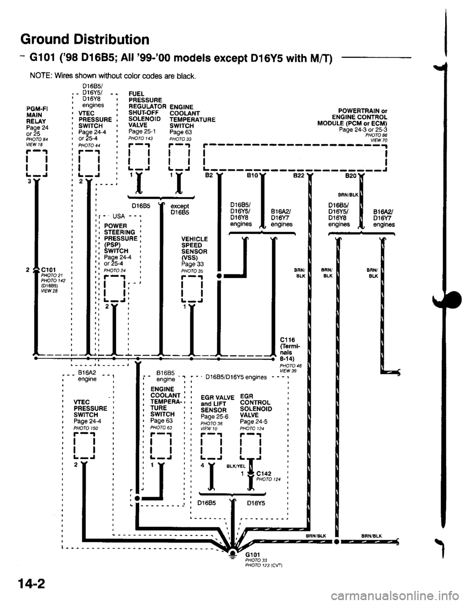
- Gl01 ('98 Dl685;All '99-'00 models except D16YS with M/T)
NOTE: Wires shown without color codes are black.
01685/_ D16Y5/ -.016Y8engrnes
.__-;,#'-_,--', engrne ;
, wEc: PRESSURE '
, swtTcH :I Page24-4 iI PHOTO 150: r -'l
:t | :
:l | :,L-J.
FUELPRESSUREREGULATOR ENGINESHUT.OFF COOLANTSOLENOID TEMPERATUREVALVE SWTTCHPage 25-1 Page 63PHOIO 143 PHOTA 33r-1F-.|
llll
lltlL-J L-J
POWERTRAIN olENGINE CONTROLMODULE (PCM or ECM)Page 24-3 ot 25-3PHOTO 86
----:y4
tl
tl
PGi,|.FIMAINRELAYPage 24ol 25
vlEw 18
tl
tl
3Y'I'I
excaptD1685
VEHICLESPEEDSENSOR(vss)Page 336FN/ELKERll/EIKcl01PHOTO 21PHOTO 142(o1685)vtEw 28
ct16Cferml-nals8n 4)
FltaFt( vttw 39t- .''iiti ' " D1685/D16Y5 engrnes ---'
t2
. ENGINE : :
i 933'?il-; i 5"T,Yf,*' 33i,"o, i
i lgfft" i I S.ir1".l^ soL€NorD :' Pase 63 : : ;;;;; - pase 24.i :' PHOTO 63 | | VtEWlO pHOIa124 ;, r-1 | , F-.t r-.r
:l | ;:l | ! | :;t | :,t | | | ;
j,f
ii T.__.,|,,,,,.
j
--
----- --l i otoas I Dr6y5 :
:------.1.--------.
14-2
o-----J
Page 1861 of 2189
Ground Distributiofl (cont'd)
- G201 andG202
NOTE: Wires shown wrthout color codes are black.
RIGHTHEAD.LIGHTPage110-12
tl
tl
110-9
{}tl
tl
LEFT FRONTPARKING/TURNSIGNALLIGHTPages 110-2,1 10-7, and110-9
()
WIND.SHIELDWASHERMOTORPage 91PHOTA 3
ll
tl
REARwtNDowWASHERMOTORPage 92
tl
tt
c205
RIGHT FRONTPARKING/TURNStcNAL RADIATORLIGHT FANPaoes 110-2, MOTOR11d-7, and Page 63
'99-'�00
.- Canada -l
i wnsxen i cnurse, FLUID ; CONTROL' LEVEL . ACTUATOR' SWITCH I paoe 34-2; Page 80-3 i eu6ro re'f-1 ' f-1
2Y2
c211
14-4
I'G201'Lv G2o2
Page 1862 of 2189
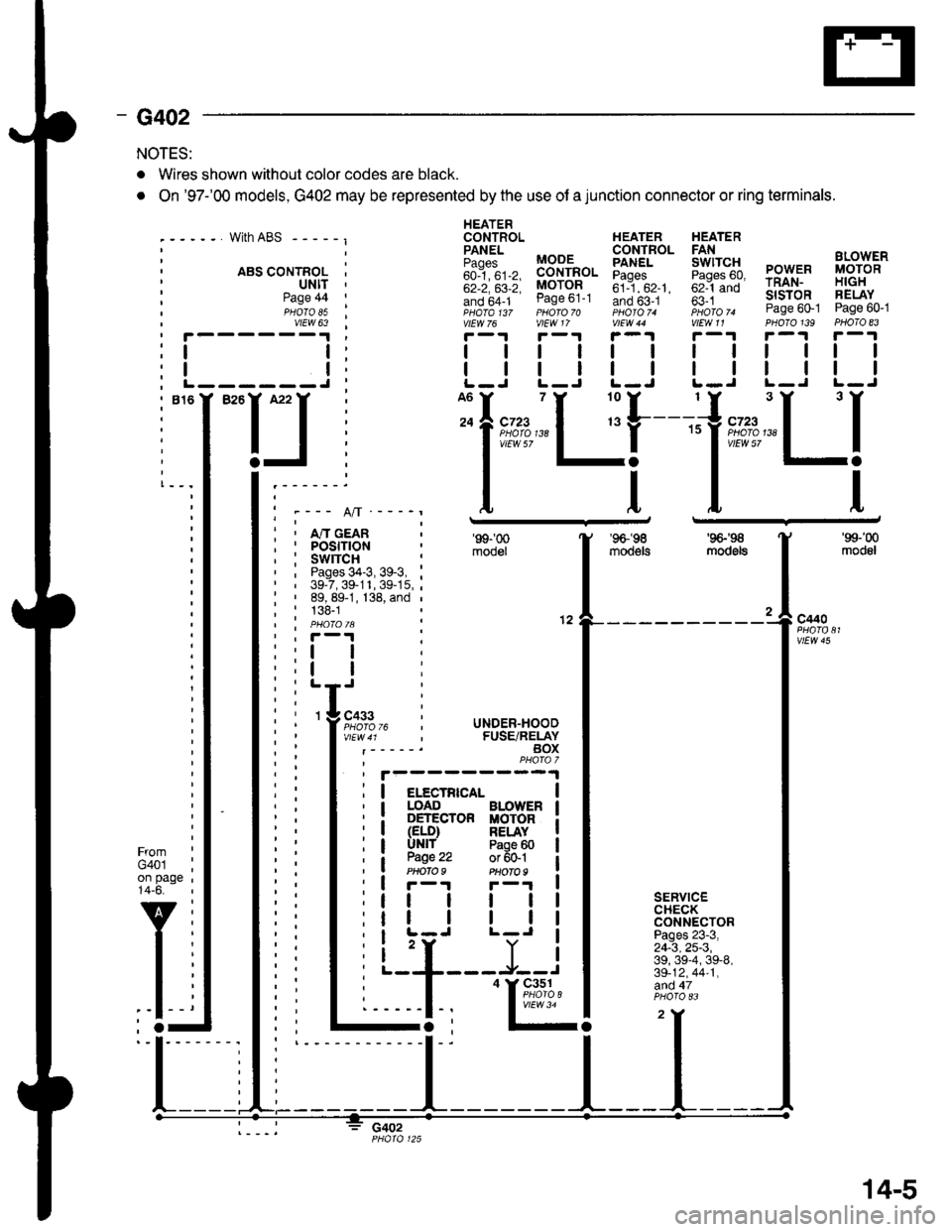
- G402
NOTES:
. Wires shown without color codes are black.
. On '97-'00 models, G402 may be represented by the use of a junction connector or ring terminals.
with ABS - - - - - I
. ABS CONTROL I' ultt '
HEATERCONTROL HEATER HEATER
iili, BB-'fi",. Eiff* 5fi::g PowER i,8;g'"'
;;; ;;; MoroR ;il--"'. ;;1-;; rRAN- H|GH
!if,6f1- ease ot-t Ino b5-.t ' fi i *- slsroR FELAY- ,pHaTa t3z pHoro 70 photoT. iioro ^ Page 60-1 Page 60-1vtEw 76 vlEW 17 V|EW 44 V|EW11 PHOTO139 PHOTO 83
r-1r-.!r-1r-1r-.|r-1
| | | | | | rl I lll
| | | | | | I ll ll IL-J L-J L-J L.J L-J L-J
Page 44PHOTO 85vtEW 63
I
I------J
I""IJ
Ifnn*"1 r'[
1"""LI'--- A/l ---_r
i , m cean; I POStflON, : swrrcH :' , Pages 34-3, 39-3, :' | 39-7,39-11,39-15,;: ' 89, 89-1, 138, and ,
; : 138-1| | PHO|OIA :' , F-'t .
'99-'00
mooel
'96-'�98
moo€ts
'9G'S
mod6ls
'99-'00
modol
a
12c440
vtEw 45
FromG401on page14-6.
v
l-
SERVICECHECKCONNECTORPages 23-3,24-3,25-3,39, 39-4, 39-8,39-12,44-1,afid 47
c402
I
I
3 cass
l;l:,12,
li
rc i UNDER-HOOD, FUSE/RELAYBOXPHAfa 7
I elecrRrca- |I LOAD BLOWER I: DETECTOR MOTOR iI (ELD) RELAY II UNlf Paoe 60 |
a W.': :;ffil iI r-r F-'r I
tt | | | |
tr | | | |I L-J L-J I
i 'r Y iL--+---J--J
I
'I&%,14.,I
14-5