Page 1475 of 2189

t
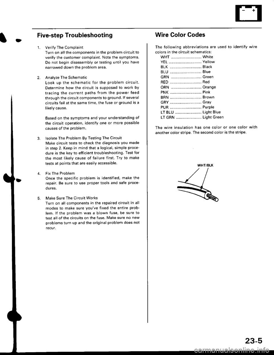
Five-step Troubleshooting
2.
1.Verify The Complaint
Turn on all the components in the problem circuit to
verify the customer complaint. Note the symptoms.
Do not begin disassembly or testing until you have
narrowed down the problem area.
Analyze The Schematic
Look up the schematic for the problem circuit.
Determine how the circuit is supposed to work by
tracing the current paths from the power feed
through the circuit components to ground. lf several
circuits fail at the same time, the fuse or ground is a
likely cause.
Based on the symptoms and your understanding of
the circult operation, identify one or more possible
causes of the problem.
lsolate The Problem By Testing The Circuit
Make circuit tests to check the diagnosis you made
in step 2. Keep in mind that a logical, simple proce-
dure is the key to efficient troubleshooting. Test for
the most likely cause of failure first. Try to make
tests at points that are easily accessible.
Fix The Problem
Once the specific problem is identified, make the
repair. Be sure to use proper tools and safe proce-
dures.
Make Sure The Circuit Works
Turn on all components in the repaired circuit in all
modes to make sure you've fixed the entire prob-
lem. lf the problem was a blown fuse, be sure to
test all of the circuits on the fuse, Make sure no new
problems turn up and the original problem does not
recur.
3.
Wire Color Codes
The following abbreviations are used to identify wire
colors in the circuit schematics:
wHT ............................. White
YEL ............................... Yellow
BLK ............,.,...............81ack
BLU .............................. Blue
GRN .............................Green
RED .......................,...... Red
ORN ............................. Orange
PNK .............................. Pink
BRN .............................. Brown
GRY .............................. Gray
PUR .,.................,.,........ Purple
LT BLU ......................... Light Blue
LT GRN ........................ Light Green
The wire insulation has one color or one color with
another color stripe. The second color is the stripe.
WHT/BLK
23-5
Page 1478 of 2189
Relay and Control Unit Locations
Dashboard: '96 - 97 models
CRUISE CONINOL UNIT
DAYTIMERUNNING LIG}ITSCONTROL UNITlCan!dal
IWire colo.s: GRN/ORN, GRN/RED,l
IWHT, YEL, and BLK I. MOONROOF CLOSE RELAYfwir. colorc: GRN/ORru, Cnru/VeLl
IWHT. GRN/RED, and ALK I
DASH LIGHTS BRIGHTNESS CONTROLLER{Has built-in control unit)
23-8
Page 1479 of 2189
D
INTEGRATEDCONTROL UNITUNDER.OASHFUSE/RELAY BOX
HORN RELAYI Wire colors: WHT/GRttt, WXf/Cnru,l
[GRY, and BLU/RED ,J
POWER WINDOW RELAY
INTERLOCK CONTROL UNIT
'gtP"tat{}r) (}t /t t ------,)
F;;snHn-nnn"nf-H-n o
F !r rr rr rr r,r Lr Ll u u l,r
Fnnnnnnnrrrr-1F rr rr rJ LJ rJ r-r t-r L-r LJ Lr ||J
u_::;_:_:_:_:_l_;I::
*TCM (CVT)
*: Coupe
23-9
Page 1533 of 2189
(l'-
Fuse NumberAmpswire ColorComponent(s) or Circuitlsl Protect€d
4180APower distribution
4240AWHT/BLKTo ignition switch (BAT)
437.5 AWHT/REDCeiling light, data link connector, trunk light
4415 AWHT/BLKPGM-Fl main relay
Not used
4640AWHT/BLUPower window motors (via power window relay)
477.5 AWHT/BLUAudio unit, clock, TCM (CVT), ECM/PCM (VBU)
4830AWHTNo.33 (7.5 A) fuse, To combination light switch (headlight)
49Not used
5030AWHT/GRNRear window defogger (via rear window defogger relay)
cl20AWHT/GRNPower door lock control unit, moonroof motor
15 AWHT/GRNHorn system, brake lights, brake signal
10 AWHT/BLKHazard warning light, turn signal/hazard rclay
54404WHT/REDOption {+B)
5540ABLU,A/VHTBlower motor (via blower motor relay)
204WHTCondenser fan motor (via condenser fan relay)
REDl'lc compressor clutch (via IVC compressor clutch relay)
204BLVBEDRadiator fan motor (via radiator fan relay)
23-6
Page 1535 of 2189

lr-
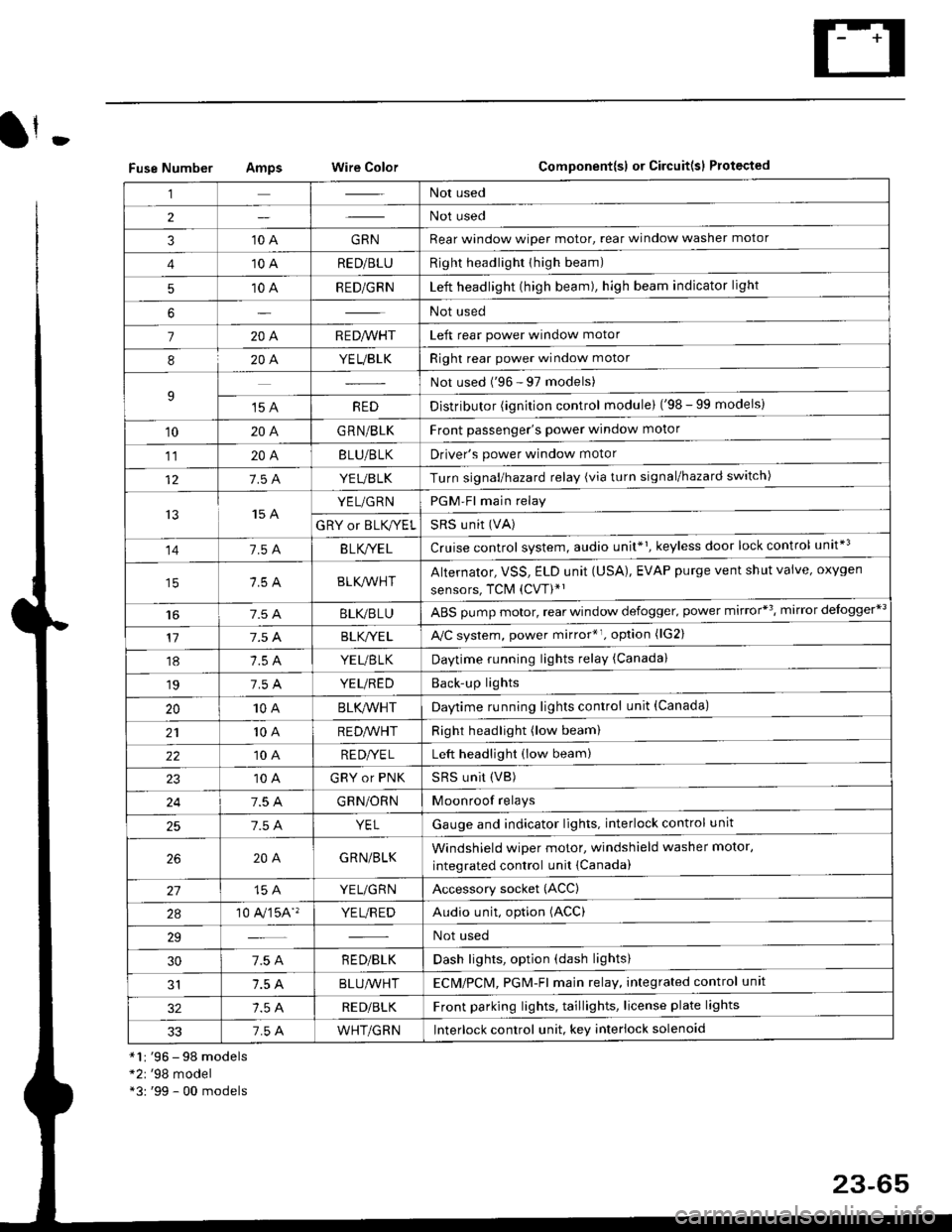
Fuse NumberAmpswire ColorComponent{sl or Circuit(sl Protected
*1r '96 - 98 models*2r '98 model*3: '99 - 00 models
,lNot used
2Not used
310 AGRNRear window wioer motor, rear window washer motor
410 ARED/BLURight headlighr thigh beam)
510 ARED/GRNLeft headlight (high beam), high beam indicator light
6Not used
7204R E D/VVHTLeft rear power window motor
820A.YEUBLKRight rear power window motor
9Not used ('96 - 97 models)
't5 AREDDistributor (ignition control module) ('98 - 99 models)
10204G RN/BLKFront passenger's power window motor
1120ABLU/BLKDriver's power window motor
127.5 AYEUBLKTurn signal/hazard relay (via turn signal/hazard switch)
t515 AYEL/GRNPGM-Fl main relay
GRY or BLK,^/ELSRS u nit (VA)
141.54B LK/YE LCruise control system, audio unit*1, keyless door lock control unit*3
BLK/lr'r'HTAlternator, VSS, ELD unit (USA), EVAP purge vent shut valve, oxygen
sensors, TCM (CVT)*'
t6BLI(,/BLUABS pump motor, rear window defogger. power mirror*3, mirror delogger*3
177.5 ABLK,/YE LA,/C system, power mirror*r. option (lG2)
18YEUBTKDaytime running lights relay (Canada)
197.5 AYEUREDBack'up lights
2010ABLK/VVHTDaytime running lights control unit (Canada)
2110 AREDA/VHTRight headlight (low beam)
2210 ARE DI/E LLeft headlight (low beam)
10 AGRY or PNKSRS UNit (VB)
247.5 AGRN/ORNMoonroof relays
257.5 AYELGauge and indicator lights. interlock control unit
204GRN/BLKWindshield wiper motor, windshield washer motor,
integrated control unit {Canada)
15 AYEL/GRNAccessory socket (ACC)
2a10 A,/'�]5A''YE L/R EDAudio unit, option (ACC)
29Not used
307.5 AR ED/BLKDash lights, option (dash lights)
1.5 ABLUA/VHTECM/PCl\4, PGM-Fl majn relay, integrated control unit
RED/BLKFront parking lights, taillights, license plate lights
337.5 AWHT/GRNlnterlock control unit. key interlock solenoid
23-65
Page 1572 of 2189
lgnition System
Component Location Index
IGNITION TIMING CONTROL SYSTEM
. Troubleshooting, section 11
. ldle speed Inspection/Adjustment. section 11
. Inspection and Setting, page 23-105
SERVICE CHECK CONNECTOR {2P}Iwiie colors: 8RN and BLKI
TEST TACI{OMETER CONNECTOB
IGNITION WIRESlnspection and Test, page 23-110
PLUGSInspection, page 23 1 11
Replacement, page 23'106Overhaul, page 23-107lgnition Coil Test, page 23'110lgnition Control Module llCM)Input Test, page 23-109
23-102
Page 1666 of 2189
Horn
Component Location Index
SRS components are located in this area. Review the SRS component locations, precautions, and procedures in the SRS
section (24) before performing repairs or service.
CABLE REELReplacement, section 24
(:-, ,,/ t.\
(6\'
\K2
HORN RELAY: '98 - 00 models-
lWire colorsr WHT/GRN, cBY,lIWHT/GRN, BLU/RED ]Test, page 23 87
HORN RELAY: '96 -97 models-lwire colors: WHT/GRN. GBY,I
IWHT/GRN, BLU/RED ITest, page 23-86
UNDER-DASH FUSE/RELAY BOX
23-196
Page 1683 of 2189
7.
8.
6. Remove the two screws, cut the wire harness, and
remove the actuator.
Record the terminal locations and wire colors'
Route the wire harness of the new actuator through
the hole in the bracket. Be sure to pass the wlre
under the bracket cliP.
BRACKET
9. Pass the connector boot over the wire harness
23-213
BLK/WHTi
,t
L,
.;{
I
oa
LT GRN I GRY
PNK
10, lnsert the terminals into the connector in the origi-
nal arrangement (recorded in step 7), as shown
Detow.
Right:
SLK/WHT*
BLU/REO'
": Canada '99 - 00 models
Apply tape to seal the intersection of the connector
boot and the wire harness.
Reassemble in the reverse order of disassembly Be
careful not to break the mirror when reinstalling it
to the actuator.
Reinstall the mirror assembly to the door.
Operate the power mirror to check that the actuator
works smoothlY.
Left:
11.
12.
13.
't 4.
PNK