1999 HONDA CIVIC wire color
[x] Cancel search: wire colorPage 360 of 2189
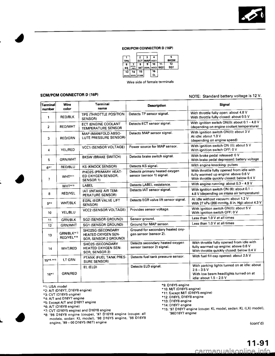
ECM/PCM CONNECTOR D I16P)
Wire side ot female terminals
ECM/PCM CONNECTOR D l16P)NOTE: Standard battery voltage is 12 V
Te.minalnumb€r
Wirecolor
Terminaln!meDor.riptionSignal
RED/BLKTPS (THROTTLE POSITION
SENSOR}
Detects TP sensor signal.With throttle fully open: about 4.8 V
With throttle fully closedl about 0.5 V
REDA/VHTECT {ENGINE COOLANTTEMPERATURE SENSORDetects ECT sensor signalWith ignition switch ON{ll): about 0.1 - 4 8 v
(depending on engine coolant lempe ratu re)
3RED/G RNMAP {MANIFOLD ABSO'LUTE PRESSURE SENSOR}Detects MAP sensor signal.With ignition switch ON(ll): about 3 V
At idle: about 1.0 V
{depending on engine speed)
YEUREDVCCl (SENSOR VOLTAGE)Power source lor MAP sensor.With ignition switch ON (ll): about 5 v
With ignition switch OFF: 0 V
5GRNMHTBKSW {BRAKE SWITCHIDetects brake switch signalWith brake pedal released: 0 v
With brake pedal depressed: baftery voltage
6*?RED/BLUKS {KNOCK SENSOR}Detects KS signal.With engine knocking: Pulses
1
PHO2S (PRIMARY HEAT-ED OXYGEN SENSOR,SENSOR 1)
Detects Primary heated oxygen
sensor (sensor 1l signal
With throttle fullv opened from idle with
Iully warmod up engine: above 0.6 V
With throttle quickly closed: below 0.4 v
LABELDetects LABEL resistanceWith engine r!nning:about 0.3 - 4.9 V
8RED//ELIAT (INTAKE AIR TEM-PERATURE SENSOR)
Detects IAT sensor signal.With ignition switch ON (ll): about 0 1 -
4.8 V {depending on intake air temperature)
9*lWHT/BLKEGRL iEGR VALVE LIFT
SENSOR)
Detects EGR valve lift sensor signalAt idle without vacuum: about'1 2 V
With 27 kPa (2OO mmHg,8 in. Hg): about 4 3 V
10YEUBLUVCC2 (SENSOR VOLTAGE)Provides sensor voltage,With ignition switch ON(ll): about 5 V
With ignition switch OFF:0 V
11GRN/BLKSG2 (SENSOR GROUND}Sensor ground.Less than 1.0 V at alltimes
12G RN,4/1r'HTSG1 (SENSOR GROUND)Ground for MAP sensor.Less than 1.0 V at alltimes
GRN/BLK*1?SHO25G (SECONDARY
HEATED OXYGEN SEN'
SOR, SENSOR 2 GROUND)
Ground for secondary heated oxy-
gen sensor (sensor 2).
14WHT/REDSH02S (SECONDARY
HEATED OXYGEN SEN'soR, sENsoR 2)
Detects secondary heated oxygen
sensor (sensor 2) signal.With throftle fully opened lrom idle with
fully warmed up engine: above 0.6 V
With throttle quickly closed: below 0.4 V
15|3. *15LT GRNPTANK {FUEL TANK PRES.
SURE SENSOR)
Detects fueltank prgssure sensor'With fuelfill caD opened: about 2.5 V
16*1GRN/RED
EL (ELD)Detects ELD signal.With parking lights turned on at idle: about
2.5 - 3.5 VWith low beam headlights turned on at
idle: about 1.5 - 2.5 V
*1: USA model*2r A/T (D16Y7, D16Y8 engine)*3: CVT (D16Y5 engane)*4: A,/T and Dl6Y7 engine*5: Except A/T and D16Y7 engine*6: A"/T (D16Y8 engine)i7: CVT (Dl6Y5 engine) and Dl6Y8 engine*8: .96 D16Y8 engine (coupei,'97 D16Y8 engine
models, sedanr KL model),'98 016Y5 engine,
engine, '99 - 00 D16Y5 (M/T) engine
*9: D16Y5 engine*10: M/T (D16Y5 engine)*11: Except M/T (Dl6Y5 engine)* 12r D16Y5. D16YB engine*13: D16Y8 engine*14: Dl6W engine*15: '97 D16Y7 engine (coupe: KL model, sedan: KL lLX) model),'98D16Y7 engine:(coupe: all'98 D16Y8
(cont'd)
1 1-91
Page 365 of 2189
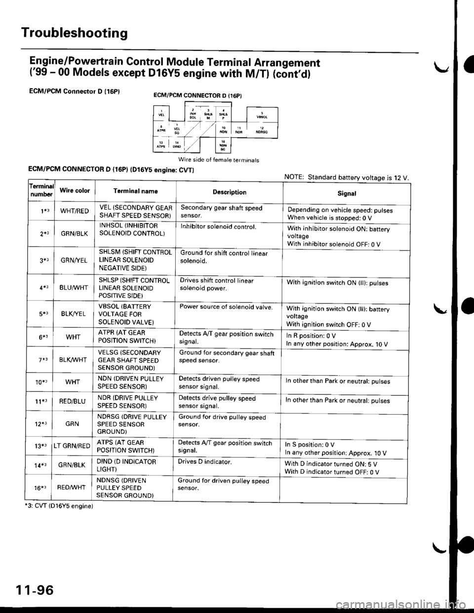
Troubleshooting
En gine/P_oweft ra in Control Module Termina I Arran gement
('99 - 00 Models except Dl6YS engine with M/Tl (cont,dl
ECM/PCM Connectol D (16P1
Wire side of female terminats
ECM/PCM CONNECTOR D {16P) (Dl6YS engine: CVTI
*3: CVT (Dl6Y5 engine)
NOTE: Standard battery voltage is 12 V
ECM/PCM CONNECTON D (r6P)
f€rminal
numDeaWire colorTerminalnameDescriptionSignal
1+3WHT/REDVEL (SECONDARY GEARSHAFT SPEED SENSOR)
Secondary gear shaft speedsensor,Depending on vehicle speed: pulsesWhen vehicle is stopped:0 V
2*3GRN/BLK
INHSOL {INHIBITORSOLENOID CONTROL)Inhibitor solenoid control.With inhibitor solenoid ON: bafteryvoltageWith inhibitor solenoid OFF: 0 V
3+3GRN/YEL
SHLSM (SHIFT CONTROLLINEAR SOLENOID
NEGATIVE SIDE)
Ground for shift control linearsolenoid.
BLU^/vHTSHLSP (SHIFT CONTROLLINEAR SOLENOIDPOSITIVE SIDE}
Drives shift control linearsolenoid power.With ignition switch ON (tl): pulses
5*3BLK,/YE LVBSOL lBATTERYVOLTAGE FOR
SOLENOID VALVE)
Power source of solenoid valve.With ignition switch ON (ll): baneryvoltage
With ignition switch OFF: 0 V
6*3WHTATPR (AT GEAR
POSITION SWITCH)Detects A,/T gear position switchsrgnal.InRposition:0V
In any other position: Approx. 10 V
BLKA/VHIVELSG (SECONDARY
GEAR SHAFT SPEEDSENSOR GROUND)
Ground for secondary gear shaftspeed sensor.
10*.WHTNDN (DRIVEN PULLEY
SPEED SENSOR)
Detects driven pulley speedsensor srgnal.In other than Park or neutral: pulses
11*3RED/BLUNDR (DRIVE PULLEY
SPEED SENSOR)
Detects drive pulley speedsensor srgnal.In other than Park or neutralt pulses
12*3GRNNDRSG (DRIVE PULLEYSPEED SENSORGROUND)
Ground for drive pulley speedsensor.
13*3LT GRN/REDATPS (AT GEARPOSITION SWITCH)
Detects Ay'T gear position switchsrgnal.In S position:0 VIn any other positioni Approx, 10 V
14*3GRN/BLKDIND 1D INDICATOR
LIGHT)
Drives D indicator.With D indicator turned ON: 5 VWith D indicator turned OFF: O V
16*rRED^/VHTNDNSG (DRIVEN
PULLEY SPEEDSENSOR GROUND)
Ground for driven pulley speedsensor.
1 1-96
Page 443 of 2189

PGM-FI System
l-Fos3sl
tFos36l
tF1361 l
Fr362-1
tF13sil
Crankshaft Position/Top Dead Center/Cylinder Position (CKP/TDC/CYPI Sensor
f99 - 00 Models except D16Y5 engine with M/T)
The scan tool indicates Diagnostic Trouble Code (DTC) P0335: A malfunction in the Crankshaft Position (CKP)
sensor circuit.
The scan tool indicates Diagnostic Trouble Code (DTC) P0336: A range/performance problem in the Crankshaft
Position (CKP) sensor circuit.
The scan tool indicates Diagnostic Trouble Code (DTC) P1361: Intermittent interruption in the Top Dead Center
{TDC) sensor circuit.
The scan tool indicates Diagnostic Trouble Code {DTC) P1362: No signal in the Top Dead Center (TDC) sensor
circuit.
The scan tool indicates Diagnostic Trouble Code (DTC) P1381: Intermittent interruption in the Cylinder Position(CYP) sensor circuit.
lTiaSt The scan tool indicates Diagnostic Trouble Code (DTC) P1382; No signal in the Cylinder Position (CYP) sensor: circuil.
DoscriDtion
The CKP Sensor determines timing for fuel injection and ignition of each cylinder and also detects engine speed. The TDC
Sensor determines ignition timing at start-up (cranking) and when crank angle is abnormal. The CYP Sensor detects the
position of No. 1 cylinder for sequential fuel injection to each cylinder. The CKP/TDC/CYP Sensor is built into the distribu-
tor.
NOTE; lf DTC P1359 is stored at the same time as DTC P0335, P0336, P1361. P1362, P1381 and/or P1382, troubleshoot DTC
P1359 first, then recheck for those DTCS. D16Y5 engino:
SENSORROTOR
TDGSENSORCKPSENSOBTDCSENSOBCKPSENSOBCYPs€NsonBOTORROTORBOTONROTOR ROTOR
D16Y7, D16Y8 ongine:
(To page 11-175)
1-174
- The MIL has been reportod on.- DTC P0335, P0336. P1361,P1362, P1381 rnd/or P1382.restored.
Problem verific{tion:1. Do the ECM/PCM Reset Proce-dure.2. Start the engine.
Intormittcnt failure, systom b OKat thb time. Check to. poor con-nections or loose wires at C120(dktributorl and ECM/PCM.
ls DTC P0335, P0336, P1361, P1362,P1381 and/or Pl382 indicated?
Check tor an open in the CKP/TDC/CYP 3enior:1. Turn the ignition switch OFF.2. Disconnect the distributor 10Pconnector,3. Measure resistance betweenthe terminals of the indicatedsensor (*see table).
Replrce the distributor ignitionhou3ing (!ee section 231.ls there 350 700 0?
SENSORDTCSENSORTEBMINAIECM/PCMTERI\,4INAICOLOR
CKPP0335
P0336
2c88LU
6c9
TDCP1361
P1362
3c20GRN
7c21BED
CYPP1381
P1342
c29YEL
Ic30BLK
Page 1139 of 2189
I
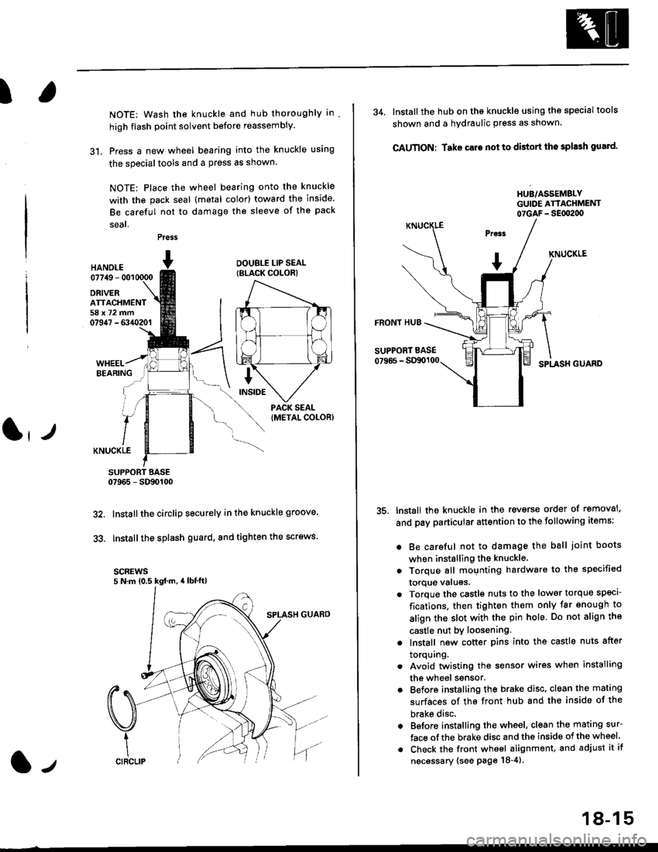
NOTE: Wash the knuckle and hub thoroughly in
high flash point solvent before reassembly.
31. Press a new wheel bearing into the knuckle using
the specialtools and a press as shown
NOTE: Place the wheel bearing onto the knuckle
with the pack seal (metal color) toward the inside
Be careful not to damage the sleeve of the pack
seal.
Press
HANOI.E07749 - 001
DRIVERATTACHMENT58x72mm07947 - 6340201
DOUBLE LIP SEAL
{BLACK COLOR)
KNUCKLE
SUPPORT BASE07965 - SD90100
Installthe circlip securely in the knuckle groove'
Installthe splash guard, and tighten the screws.
scREws5 N.m (0.5 kgd m, 4lbt'ft)
32.
33.
l-,
18-15
34. lnstall the hub on the knuckle using the specialtools
shown and a hydraulic press as shown.
CAUTION: Take care not to distort tho splash gusrd'
HUB/ASSEMBLYGUIDE ATTACHMENT07GAF- SEflt2d)
KNUCKLE
FRONT HUB
SUPPORT BASE
07966 - StXx)100SPLASH GUARD
tnstall the knuckle in the reverse order of removal'
and pay particular attention to the following items:
. Be careful not to damage the ball joint boots
when installing the knuckle.
. Torque all mounting hardware to the specified
torque valugs.
. Torque the castls nuts to the low€r torque specl-
fications, then tighten them only far enough to
align the slot with the pin hole. Do not align the
castle nut by loosening.
. lnstall new cotter pins into the castle nuts after
torquing.
. Avoid twistin0 the sensor wires when installing
the wheel ssnsor.
. Before installing the brake disc, clean the mating
surfaces of the front hub and the inside of the
brake disc.
. Before installing the wheel, clean the mating sur-
face ofthe brake disc and the inside of the wheel
. Check the front wheel alignment, and adjust it if
necessary (see page 18-4).
Page 1205 of 2189
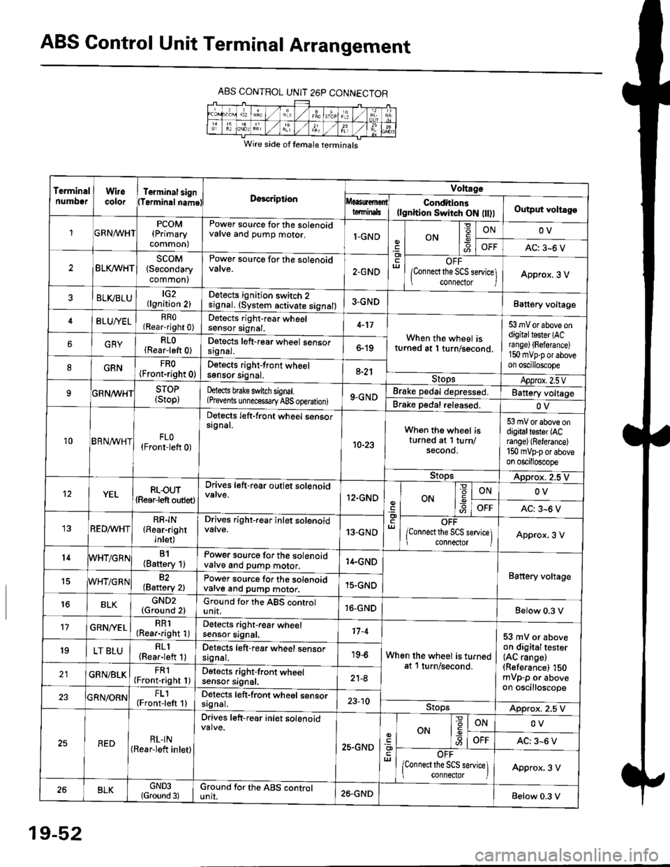
ABS Control Unit Terminal Arrangement
ABS CONTROL UNIT 26P CONNECTOR
Wire side of temale terminals
Terminalnumo0rWirecolorTerminal signTerminalnamoDgscriptionVoltage
Conditions(lgnition Switch ON flt))Output voltagoteminals
PCOM(Primary
common)
Power source for the solenoidvalve and pump motor.1-GNDON
=ONOV
AC: 3-6 V
BLK/WHTscoM(Secondary
common)
Power source for the solenoid
2.GNDOFF
lConnect the SCS service\
conneclor lApprox. 3 V
ELVBLUtG2(lgnition 2)Detects ignition switch 2
!9nal. (system activate signal)3-GNDBatt€ry voltage
BLU/YELRRO(Rear-right 0)Detects right-rear wheelsensor signal.4-17
When the wheel isturned at 1 turn/second.
53 mV or above ondigitaltester (ACra nge) {Fefera nce)150 mvp-p or aboveon oscilloscope
6GRYRLO(Rear-left 0)Detects left-rear wheel sensorsrgnal.6-19
8GRNFRO(Front-right 0)D€tects right-front wheelsgnsor srgnal,a-21StopsApprox.2.5VSTOP(Stop)hects brake switch signal.(Prevents unnecess€ry ABS operation)9-GNDBrake pedal depressed.Battery voltage
Brake pedal released.OV
10BRN^/vHTFLO(Front-left 0)
Detects left-front wheel sensorsignal.
10-23
When the wheel isturned at 1 turn/secono.
53 mV or above ondigitaltester (ACrange) (Referance)
150 mVFporaboveon oscilloscope
9!opsApprox. 2.5 V
12YELRLOUT(Rearjeft outlet)
Drives left-rear outlet solenoid
12.GNDON-9ONOV
OFFAC: 3^6 V
REDMHTRR]N(Rear-right
inlet)
Drives right-rear inlet solenoidvalve.13-GNDOFF
lconnect the SCS service]i connector IApprox. 3 V
14B1(Battery 1)Power source for the solenoidvatve and pump motor.14.GND
Battery voltage15WHT/G R N82(Baftery 2)Power source for the solenoidvarve ano pump motor.15.GND
r6BLKGND2{Ground 2)Ground for the ABS controlunit.16-GNDBelow 0.3 V
17GRN/'/ELRR1(Rear-right 1)Detects right-rear wheelsensor signal.17-4
When the wheel is turnedat 1 turn/second.
53 mV or aboveon digitaltester(AC range)(Referance) 150mVp-p or aboveon oscilloscope
19LT BLURLl(Rea.-left 1)Detects left-rear wheel sensorsagnal.19-6
GRN/BLKFRl(Front-right 1)Detects right-front wheelsensor signal.21-8
FL1(Front-left 1)Detects left-front wheel sensorsignal.23-10StopsApprox. 2.5 V
REDRL-IN(Rear-lett inletl
Drives left-r€ar inlet solenoid
25.GND
ut
ON
'6
-9ONOV
OFFAC: 3-6 V
OFF
lconnect the SCS service] connector lApprox. 3 V
BLKGND3(Ground 3)Ground for the ABS cgntrolunit.26.GNDBelow 0.3 V
19-52
Page 1381 of 2189
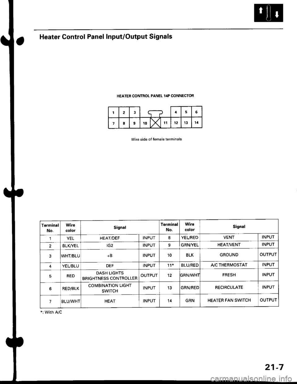
Heater Control Panel Input/Output Signals
HEATER CONTROL PANEL lilP CONNECToR
Wire side of lemale terminals
21-7
Terminal
No.
Wire
colorSignalTerminal
No.
Wire
colorSignal
1YELHEAT/DEFINPUT8YEVREDVENTINPUT
BLfiELINPUT9G RNI/ELHEATIr'ENTINPUT
WHT/BLU+BINPUT'10BLKGROUNDOUTPUT
4YEUBLUDEFINPUT11*BLU/REDA./C THERMOSTATINPUT
5REDDASH LIGHTS
BRIGHTNESS CONTROLLEROUTPUT12GRN/WHTFRESHINPUT
6RE D/8LKCOMBINATION LIGHT
SWITCHINPUT13GRN/REDRECIRCULATEINPUT
1BLUMHTHEATINPUT14GRNHEATER FAN SWITCHOUTPUT
Page 1410 of 2189
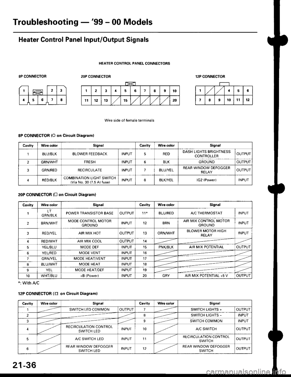
Troubleshooting -'99 - 00 Models
Heater Control Panel Input/Output Signals
HEATER CONTROL PANEL CONNECTORS
8P CONNECTOR2OP CONNECTOR12P CONNECTOR
Wire side of female terminals
8P CONNECTOR (O qn Circuit Diagram)
20P CONNECTOR {D on circuit Diagram}
*: with Ay'c
12P CONNECTOR (tr on Circuit Diagraml
CavityWire colorSignalCavilyWhe colorSignal
BLU/8LKBLOWER FEEDBACKINPUT5REDDASH LIGHTS BRIGHTNESSCONTROLLEROUTPUT
2GRN/lVHTFRESHINPUT6BLKGBOU N DOUTPUT
3GRN/REDRECIRCULATEINPUT7BLU/YELREAR WINDOW DEFOGGERRELAYOUTPUT
4RED/BLKCOMBINATION LIGHT SWITCH(Via No. 30 (7.5 A) fuse)INPUT88LfiELlG2 {Power)INPUT
CavityWire colorSignalCavityWire colorSignal
LTGRN/BLKPOWER TRANSISTOR EASEOUTPUT't1BLU/REDAy'C THERMOSTATINPUT
2BRNMHTMODE CONTROL MOTORGROUNDINPUT12BRNAIR MIX CONTROL MOTORGROU NDINPUT
3RE D/YELAIR MIX HOTOUTPUT13ORNAA/HTBLOWER MOTOR HIGHRELAYINPUT
RED,ryvHIAIR MIX COOLOUTPUT14
5YEUBLUMODE DEFINPUTPN K,/BLKAIR MIX POTENTIALOUTPUT
6YEUREDMODE VENTINPUT16
7GRNI/ELMODE HEAT/r'ENTINPUT11
IBLUAVHTMODE HEATINPUT18
9YELMODE HEAT/DEFINPUT19
10WHT/BLU+B (Power)INPUT20GRYAIR MIX POTENTIAL +5 VOUTPUT
CavityWilecolorSignalCavityWi.e cololSignal
lSWITCH LED COMMONOUTPUT1SWITCH LIGHTS +OUTPUT
2ISWITCH LIGHTS -INPUT
39SWITCH COMMONINPUT
4RECIRCULATION CONTROLSWITCH LEDINPUT10A,/C SWITCHOUTPUT
5A./C SWITCH LEDINPUT11RECIRCULATION CONTROLSWITCHOUTPUT
6REAR WINDOW DEFOGGERSWITCH LEDINPUT12REAR WINDOW DEFOGGEBSWITCHOUTPUT
21-36
Page 1471 of 2189

l'f .
Electrical
Special Toofs .,....................,23-2
Troubleshooting
Tips and Precautions ..............,.................... . 23-3
Five-step Troubleshooting .............. ......... . . 23-5
wire color codes ..........,23-5
Schematic Symbols ........,................... . . .. .... 23-6
Relay and Control Unit Locations
Engine Compartment ...,..................... ... .. . 23'7
Dashboard ......................23-8
Dashboard/Door ......... 23-12*Airbags ................. ....... Section 24
Air Conditioning ......... Section 21
Aftelnator ..........."""" """ 23-112
Anti-lock Brake System {ABS) Section 19*A/T Gear Position Indicator .....................,. .... ... 23-149
Automatic Transmission Svstem .... . ....... Section 14
Batterv ......... . . . ... ...... .......23-91
Blower controls .. . ... Section 2l
Charging System ....'...........23'112
Connector ldentilication and Wire Harness
Routing .................. ......23'13
Cruise Control ............,........23-240
Dash Lights Brightness Controller ............. ....... 23-180
Fan controfs "" 23'126
Fuel PumD ........ . ........ section 11
Fuses/Refay ...............,..,,.. 23'62
PGM-FI Control System ......................,....... Section 1 1
*Gauges
Circuit Diagram ....,.,.......23-131
Fuef Gauge ...........'.'.......23-142
Gauge/lndicator .. . .. 23-129
Ground Distribution .. . 23-75
Heatei controls .. . ..... Section 21*Horn................. ...............23-196
*tgnition Switch ....................23-89
lgnition System .......,.... 23-102
*lntegrated Control Unit ....................................... 23-156
fnterlock System ,........ . . , ,23-144
Lighting System . . . .. ......... 23-161
Lights, Exterior
Back-up Lights ..'............23'171
Brake Lights .................. 23'174
Daytime Bunning Lights (Canadal ............... 23'166
Front Parking Lights ......,................ .'. .......... 23-167
Front Turn Signal Lights .......... . . ............ ..,.23-167
Headtights ....".'....-... ..... 23'167
High Mount Brake Light ...................... ... .23'179
License Plate Lights ...... 23'176
Taitfights ................ .......23'171
lnterior Lights ..-.......,, . 23-142
Moonroof ..,.................,........ 23-235
Power Distribution ....... . . .23-61
Power Door Locks .......,,,. .23'251
Power Mirrors ,..............,.,...23'206
Power Relays ....... . ...... . . .. 23-86
Power Windows ............,,....23-220
Rear Window Defogger .......................... . . ... . . 23-2OO
Spark Plugs . ..... . ........ .....23-111
Slarting System ................23-93*stereo Sound Svstem ,................. ..... ... . ... ,.,.,,23'147'Supplemental Restraint System (SRS) ... . Section 24
Turn Signal/Hazard Flasher System .......'.'....-... 23-173
*Undel-dash Fuse/Relay Box ............,.................. 23-85
vehicfe soeed sensor (VSSI """" ""' 23-140+Wipers/Washers .........,.,.,...23-214
NOTE: Unless otherwise specified, references to auto-
matic transmission (Mf) in this section include the CVT.