Page 1341 of 2189
Trunk lid or Hatch/Fuel lid opener:
NOTE: Remove the side trim (see pages 20 59,60.61)
>: Boll locations, 2
OPENER LOCK
6xl.0mm9.8Nm11.0 kgf.m,7.2 tbl.ttl
a@- CYLINDER
Ya//t2't4Dl
ti
TBUNK LID/HATCHOPENER CABLE(see20-108, 110)
To trunk lid latchor striker.
To fuel lid latch. \
FUEL LIDOPENER CABLE(see pages 20-108, '110)
Installation is the reverse of the removal procedure
NOTE:
. lvake sure the opener cable is connected properly.
. Make sure the trunk lid or hatch and fuel lid open
properly.
l:'.j
Striker (3Dl:
NOTE: Remove the rear trim panel (see page 20-60)
>: Bolt locations, 2
6xl.0mmHATCHOPENER CAELE(see page 20-110)
lnstallation is the reverse of the removal procedure.
NOTE:
. N4ake sure each
erlY.
. Make sure the
securelY.
opener cable is connected ProP-
hatch opens properly and locks
(cont'd)
20-111
Page 1342 of 2189

Opener and Latch
Replacement (cont'd)
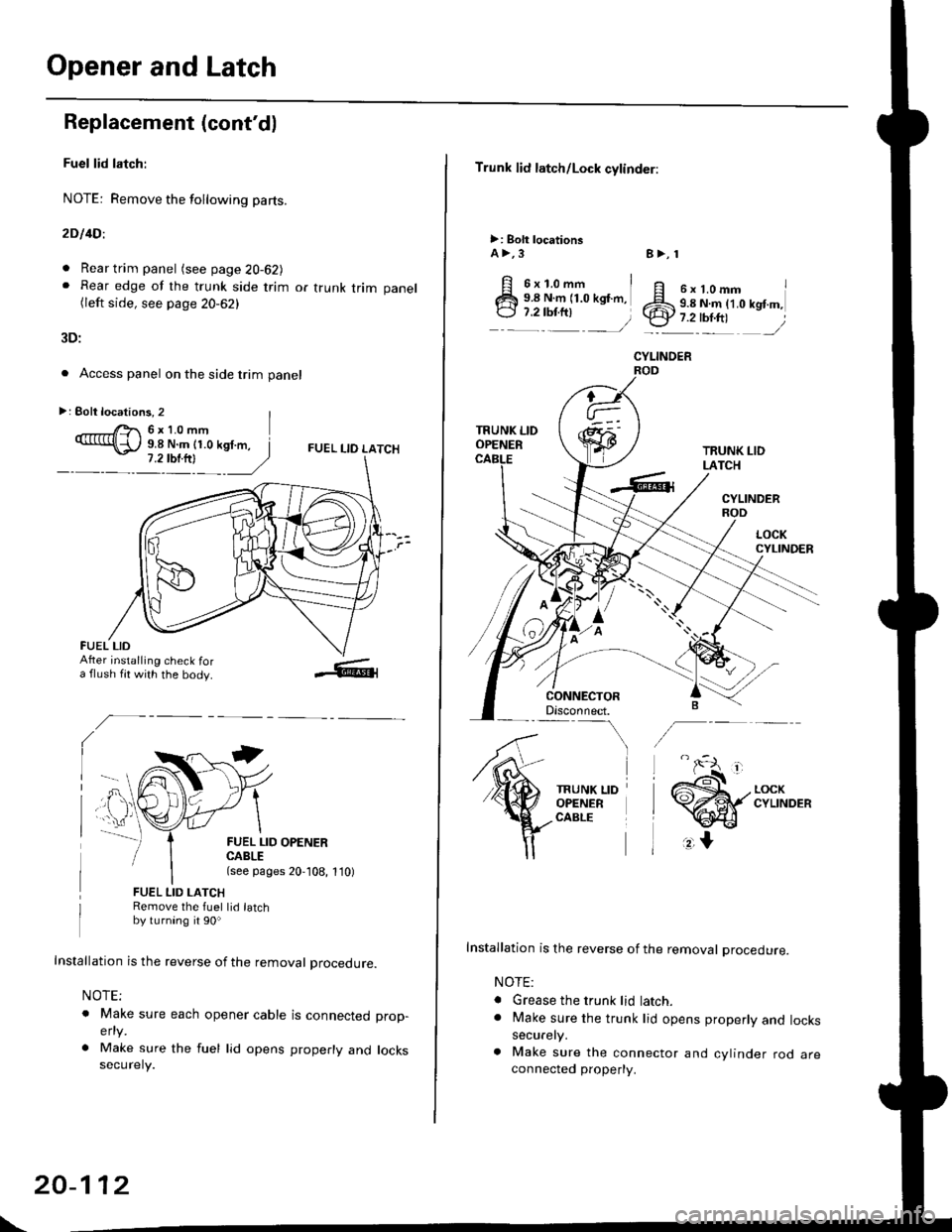
Fuel lid latch:
NOTE: Remove the following pa(s.
2D l4Dl
. Rear trim panel (see page 20-62J. Rear edge of the trunk side trim or trunk trim panel(left side, see page 20-62)
3D:
. Access panel on the side trim panel
FUEL I-IO LATCH
II
FUEL LID OPENERCABLE(see pages 20,108, 1'10)
FUEL LID LATCHRemove the fuel lid latchby turning it 90o
Installation is the reverse of the removal procedure.
NOTE;
o Make sure each opener cable is connectedelty
. Make sure the fuel lid opens properly andsecurely.
prop-
locks
>: Eolt locations, 2 |r'- 6x10mm9.8 N.m (1.0 kgf.m, I
FUEL LIDAfter installing check fora flush fit with the body.
\
20-112
Trunk lid latch/Lock cylinder:
>: Bolt locationsA >,3
6x1.omm i9.8 N.m (1.0 kgf.m,
:::^ _=)
TRUNK LIDOPENER
CONNECTORDisconnect.-\
TRUNK LIDOPENERCABLE
8>, 1
ff e rt.omm IZS 9.8 N.ln (1.0 kgt m,.ty 7.2-tbr.ftt ,/
CYLINOER
TRUNK LIDLATCH
CYLINDERROD
Installation is the reverse of the removal procedure.
NOTE:
. Grease the trunk lid latch.. Make sure the trunk lid opens properly and lockssecurely.
a Make sure the connector and cylinder rod areconnected property.
Page 1343 of 2189
Windshield Wiper Arms
and Linkage
Hatch latch/Lock cylinder:
NOTE: Remove the hatch trim panel (see page 20-63).
>: Bolt locationsA>,3
6x1.0mm I9.8 N.m i1.0 ksf m,l
1.2lbl.trl /
B>, 1
E6'cr
CYLINDER
6;:il;l,lr'.",
.r\
LOCK- r€ cYLTNDERL^ ! ./
rAs<.L ,/
\faa"El
rl
lnstallation is the reverse of the removal procedure.
NOTE:
. Grease the hatch latch.
. Make sure the hatch opens properly and locks
securely.
. Make sure the cylinder rod is connected properly.
Replacement
CAUTION: Pul on gloves to protect your hands
NOTE: Take care not to scratch the hood and body.
1. Remove the windshield wiper arms, then remove
the hood seal and cowl cover.
>: Clip locationsA>,9 B>,9WINOSHIELDWIPER ABMS
\j:_
Hw
u
cowl covER
Disconnect the connector, then
shield wiper linkage assemblY.
Japan/Canada-produced:
remove the wind-
10 x 1.25 mm18 N.m ll.8 kgf m,
(cont'd)
20-113
Page 1344 of 2189
Windshield Wiper Arms and Linkage
Replacement (cont'dl
USA-produced:
3. Separate the windshield wiper linkage and wind-
shield wiper motor.
Japan/Canada-produced:
NOTE: Scribe a line across the link and windshield
wiper linkage to show the original adjustment.
>: Bolt locations, 3
O 6r1.0mm
EF 8 N.m {0.8 kstm,ig 5.8 tbf.ft) )
NUT10 x 1.25 mml8 N rn (1.8 kgtm,13 tbtftl
>r Bolt locations,3
WIPER LINKAG€
\
20-114
USA-produced:
NOTE: Scribe a line across the link and windshield
wiper motor to show the original adjustment.
>: Bolt locations, 2
R 6J( 1.0 mm
Y 8 N.m to.s kgtm, I
.E- 7Y.nt )
NUT10 x 1.25 mm'18 N.m {1.8 kgf.m.13 tbtft)
WINDSHIELDWIPER MOTOR
4. Installation is the reverse of the removal procedure.
NOTE:
. Make sure the connector is connected properly.
. lf necessary, replace any damaged clips.
. lnstall the windshield wiper arms as described
on page 20-1'17.
. Check the windshield wiper motor operation.. Grease the moving parts.
Page 1345 of 2189

Rear Window Wiper
Arm and MotorWasher Reservoir
Replacement
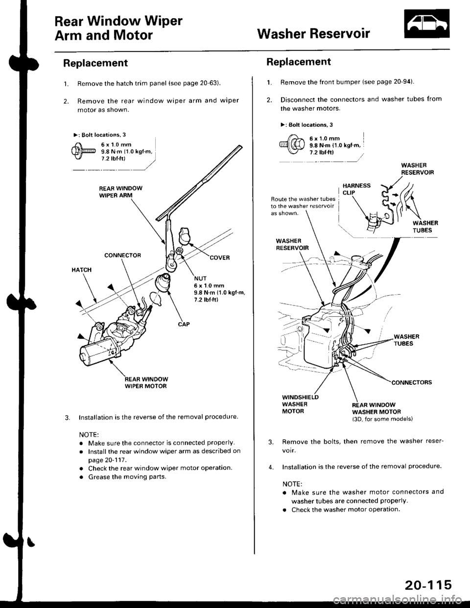
't.
2.
Remove the hatch trim panel (see page 20 63).
Remove the rear window wiper arm and wiper
motor as shown.
Installation is the reverse of the removal procedure
NOTE:
. Make sure the connector is connected properly
.Install the rear window wiper arm as described on
page 20-117.
. Check the rear window wiper motor operation.
. Grease the moving parts.
3.
NUT6x1.0mm9.8 N.m 11.0 kgf.m,7.2 tbf.ft)
WIPER MOTOR
L
2.
Replacement
Remove the front bumper (see page 20-94).
Disconnect the connectors and washer tubes from
the washer motors.
>: Bolt locations,3
/)^ 6xt.omm
Ql(S) s.e ru.- tt.o ret '".\./ 7 .2 tbf.ft) /
Route the washer tubes10 the washe. reservoir
wtNDowWASHER MOTOR(3D, for some models)
Remove the bolts, then remove the washer reser-
voir.
Installation is the reverse of the removal procedure.
NOTE:
a Make sure the washer motor connectors and
washer tubes are connected properly.
. Check the washer motor operation.
3.
4.
20-115
Page 1346 of 2189

Washer Tube
Replacement
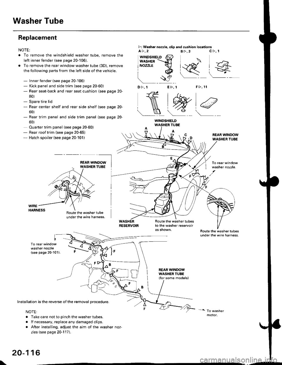
NOTE:
. To remove the windshield washer tube, remove the
left inner fender (see page 20-106),
. To remove the rear window washer tube {3D), remove
the following parts from the left side of the vehicle.
- Inner fender (see page 20-106)- Kick panel and side trim (see page 20-60)- Rear seat-back and rear seat cushion (see page 20-
80)- Spare tire lid- Rear center shelf and rear side shelf (see page 20-
60)- Rear trim panel and side trim panel
60)
Ouarter trim panel (see page 20-60)- Rear roof trim {see page 20-65)- Hatch spoiler (see page 20-101)
(see page 20
WIREHARNESS
>: W.sher nozzle, clip and cushion locationsa>,2B>,3
"J>)
[q@"
F>, 11
c>, 1
wttrtosnteLo 6}usxea =-d
lNozzrE cv
iq
!$e
D>,1 E>, 1
NtW)€
Roote the washer tubeunder the wire harness.
TUBE
A
Route the washer tubesto the washer reservoir
REAB WINDOWWASHER TUBE(Ior some models)
REAR WINDOWWASHER TUBE
washer nozzle.
washer nozzle(see page 20-101).
oo\
Installation is the reverse of the removal procedure.
NOTE:
. Take care not to pinch the washer tubes.
. lf necessary, replace any damaged clips.
. After installing, adjust the aim of the washer noz-
zles (see page 20-117).
20-116
WINDSHIELD
\,--
Page 1355 of 2189
Rear Seat
RemovaUlnstallation
3D:
>: Bolt locationsa>,6
i_): Hook locations4i.,,2
c>, 1
Bt-;,1
T=ttJX,.)MIOOLE FLOORCENTER GUSSET
6x1.Omm9.8 N.m {1.07.2 tbt.trl
STRIKERRemove the side trimpanel (see page 20 60).
.2 tb,f.ft)
--::.........VV
STNIKER
>: Clip locations, 14
l@nIFF(EE
\qt
;*... 1PIVOTBRACKET
SEAT CUSHION
HOOK
A
c
Pivot boft con3truction:
TOOTXEDLOCKWASHERSEAT.BACK
A
Instailation is the reverse of the removal procedure.
NOTE:
. Before attaching the seat-back and seat cushion, make sure there are
center belt.
. When installing the seat cushion, slip the seat belt buckles through the
. Make sure the seat-back locks securely.
. lf necessary, adjust the striker and seat-back.
20-126
PIVOT BOLT BRACKET8 x 1.25 mm22 N.m 12,2 kgf,m, 16 lbl.ftlApply liquid thread lock.
no twists or kinks in the rear seat belts and
slits in the seat cushion.
iI
*nt.]
j
6x1.0mm9.8 N.m {1.0
B>,'t
I
-@e ' t.o.- |S=222 N.m 12.2 kg{.m,Ig 16 tbf.ft) j
:,/
I
I
Ifgf..,i
l
)
l---
Page 1357 of 2189

Front Seat Belt
RemovaUlnstallation
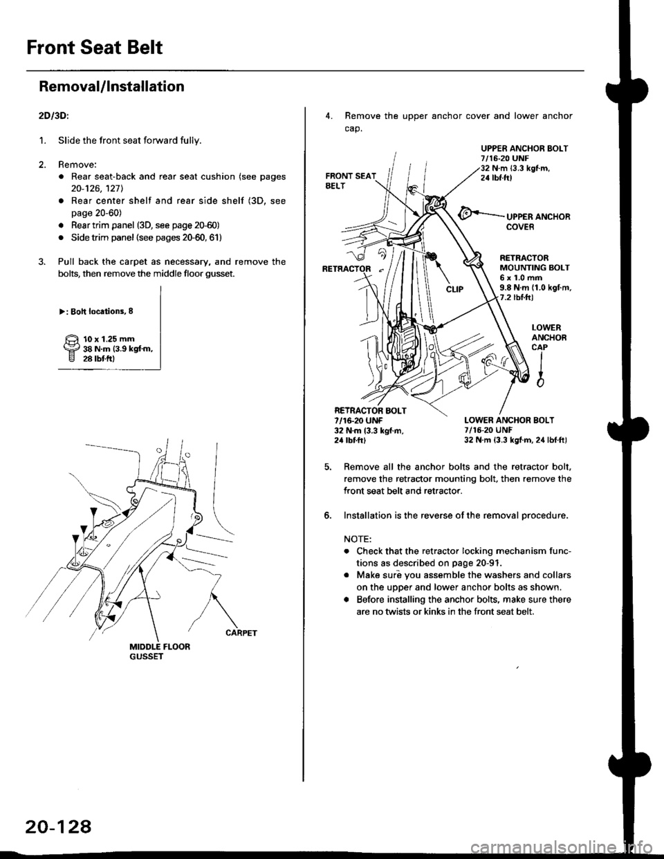
2D l3Dl
1. Slide the front seat forward fully.
2. Remove:
. Rear seat-back and rear seat cushion (see pages
20-126,127l.
. Rear center shelf and rear side shelf (3D, see
page 20-60)
. Resr trim panel (3D, see page 2G60)
. Side trim panel (see pages 20-60, 61)
3. Pull back the carpet as necessary, and remove the
bolts, then remove the middle floor gusset.
>: Boh locations,8
10 x 1.25 mm38 N.m (3.9 kgf'm,28 rbtftl
20-124
4. Remove the upper anchor cover and lower anchor
cap.
UPPER ANCHOR EOLT7/16-20 UNF32 N.m {3.3 kgf.m,24 tbf.ftt
UPPER ANCHORCOVER
LOWERANCHOBCAPIIio
RETRACTORMOUNTING BOLT6x1.0mm9.8 N.m (1.0 kgf.m.7.2 tbl.hl
LOWER ANCHOR BOLT7/16-20 UNF32 N.m (3.3 kgt.m, 24 lbf.ft)
Remove all the anchor bolts and the retractor bolt.
remove the retractor mounting bolt, then remove the
Iront seat belt and retractor.
Installation is the reverse of the removal orocedure.
NOTE:
. Check that the retractor locking mechanism func-
tions as described on page 20-91
o Make suri vou assemble the washers and collars
on the upper and lower anchor bolts as shown.
. Before installing the anchor bolts, make sure there
are no twists or kinks in the front seat belt.
RETRACTOR AOLT7/16-20 UNF32 N.m 13.3 kgf.m,24 tbttrl
6.