Page 1322 of 2189

Seat Belts
Child Seat Anchor Plate
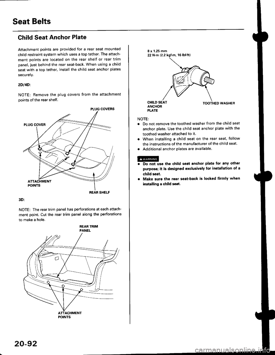
Attachment points are provided for a rear seat mounted
child restraint system which uses a top tether. The attach-
ment points are located on the rear shelf or rear trim
panel, just behind the rear seat-back. When using a child
seat with a top tether, install the child seat anchor plates
securely.
2Dl4Di
NOTE; Remove the plug covers from the attachment
points of the rear shelf.
3D:
NOTE: The reartrim panel has perforations at each attach-
ment point. Cut the rear trim panel along the perforations
to make a hole.
REAR TRIMPANEL
PLUG COVERS
REAR SHELF
POINTS
20-92
NOTE:
TOOTHED WASHEB
Do not remove the toothed washer from the child seat
anchor plate. Use the child seat anchor plate with the
toothed washer attached to it.
When installing a child seat on the rear seat, follow
the instructions of the manufacturer of the child seat
Additional anchor olates are available.
@r Do not us6 the child seat anchor plate for any othel
purposs; it is designed exclusively tor installation of a
child 3eat.
. Make suro the rear seat-back is locked firmly when
installing 8 child seat.
Page 1323 of 2189
Exterior
Component Location Index
NOTE: Refer to the Civic BodV Repair Manual, '1996 Model Series, P/N.6150330,forthe hood, trunk lid and hatch removal.
2Dl30llDl
LICENSE PLATETRIM TRUNK LIDROOF MOLOINGReplacement,
SIDE WINDOWMOLDINGSReplacement,page 20-102Replacement,page 20-100Adjustment, page 20-97Tolsion Bar Removal,page 20-10220 99
HOODAdiustment, page 20 96Hood Edge protector
Replacement, page 20 99
TRUNK LIDWEATHERSTRIPReplacement,page 20-100
REAR BUMPERReplacement,page 2O-95
SILL PANELReplacement, page 20 105
REAR AIR OUTLETReplacement,page 20-106
FUEL PIPEPROTEfiORReplacement,page 20-106
FENDERWELL TRIMReplacement, page 20-106
Replacement,page 20-106
3D:
HATCH
HATCHAdjustment,page 20-98
WEATHERSTRIP
20-93
Page 1330 of 2189
Trunk Lid/Hatch
WeatherstripLicense Plate Trim
Replacement
When installing the trunk lid/hatch weatherstrip. align it
with the alignment mark on the trunk lid/hatch opening.
NOTE:
. Make sure there are no wrinkles in the weatherstrip.
. Check for water leaks.
2DllDi
STEEI.CORE
3D:
ALIGNMENTMARK (2Dl4D)
ALIGNMENT MARK
WEATHERSTRIP
ALIGNMENT MARK
BODY
\
20-100
Replacement
CAUTION: Put on glov€s to plotest your hands.
NOTE: Take care not to scratch the trunk lid/hatch.
1. Remove the license plate.
2, 3D: Remove the hatch trim panel (see page 20-63).
3. Remove the nuts and clips, and detach the clip, then
remove the license plate trim.
NOTE: Take care not to drop the nuts inside the trunk
lid/hatch.
a: Nut locations,2
6fi\5x0.8mm Irvr?// 1,8 N.m {0.18 kst.m,l- j llrftl ,/
>: Clip locations,
InA
aa# )
-,/
Installation is the reverse of the removal orocedure.
NOTE: lf necessary, replace any damaged clips.
Page 1333 of 2189
Door and Side Moldings
Replacement
CAUTION: When prying with a flat-tip scr6wdrivgr, wrap it with protective tape to prevent damags'
NOTE;
. To remove the front side molding, remove the inner fender (see page 20-106)'
. To remove the door moiding, remove the door panel (see pages 20-4, 10, 16) and plastic cover.
. To removethe rearside molding, remove the side trim panel (see pages 20-60,611'
. Take care not to bend the door moldings.
. Before reassembling, clean the door bonding surface with a sponge dampened in alcohol'
. After cleaning, keep oil, grease and water from getting on the surface'
. lf necessary, replace any damaged clips.
4D:
FRONT DOORAdhesive areas.
2Dl3Dl
B>,3c>,2
REAR SIDEMOLOING
a: Plastic nut loc€tion. 1
@)
(cont'dl
20-103
MOLDING
>: Clip locations
A >: 4D, 112')13D,7
Page 1334 of 2189

Door and Side Moldings
Replacement (cont'dl
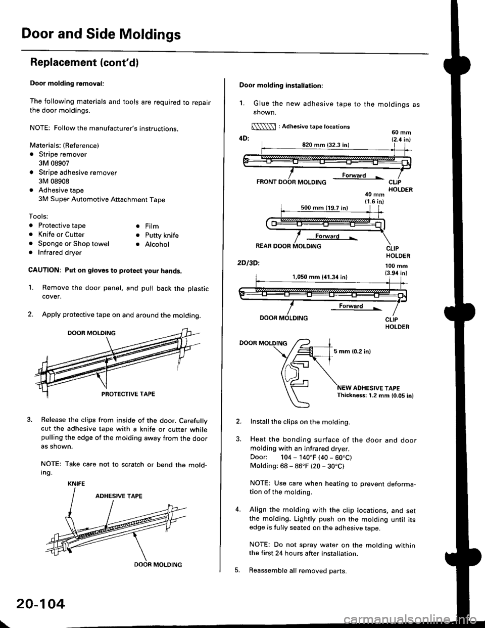
Door molding removal:
The following materials and tools are required to repairthe door moldings.
NOTE: Followthe manufacturer's instructions.
Materials: (Reference)
. Stripe remover
3M 08907
Stripe adhesive remover
3M 08908
Adhesive tape
3M Super Automotive Attachment Tape
Tools;
a Protective tape
. Knife or Cutter
. Sponge or Shop towel. Infrared dryer
. Film
. Putty knife
. Alcohol
CAUTION: Put on gloves to protect your hands,
Remove the door panel, and pull back the plastic
cover,
Apply protective tape on and around the molding.
3. Release the clips from inside of the door. Carefullvcut the adhesive tape with a knife or cutter whilepulling the edge of the molding away trom the dooras shown.
NOTE: Take care not to scratch or bend the mold-Ing.
1.
KNIFE
DOOR MOLDING
\
20-104
Door molding installation:
1. Glue the new adhesive tape to the moldings assnown.
[\\\l : Adhesive tape tocations60 mm4D: t2 t i^l
40 mm11.6 in)
Forward L
REAR DOOR
2Dl3Dl
CLIPHOLDER
100 mm(3.94 inl1,050 mm 141.34 inl
Forward !
DOOR MOLDING
DOOR MOLDING
5 mm {0.2 inl
ADHESIVE TAPEThickness: 1.2 mm 10.05 in)
Installthe clips on the molding.
Heat the bonding surface of the door and doormolding with an infrared dryer.
Door: 104 - 140"F (40 - 60.C)Molding: 68 - 86"F (20 - 30.C)
NOTE: Use care when heating to prevent deforma-tion of the molding.
Align the molding with the clip locations, and setthe molding. Lightly push on the molding until itsedge is fully seated on the adhesive tape.
NOTE: Do not spray water on the motding withinthe first 24 hours after installation.
Reassemble all removed pans.
Page 1335 of 2189
Side Sill Panel
Replacement
NOTE:
. Take care not to scratch the body
. 4D shown here;2D and 3D removal procedure is the same as 4D'
>: Screw locations, 4
W_1
NOTE: Loosen the screw,
then remove the lower cliP
using a clip remover.Remove the side cliPs from the body
by turning them 45"
To install the side sill panel, remove the side clips from the body.
panel on the car.
NOTE:
. Take care not to twist the side sill panel.
. lf necessary, replace any damaged side and lowerclips'
NOTEr When removing the side
sill panel, the side clips will
stay in the body.
SIOE SILL PANELRemove the lower cliPs,then remove the side sill Panelby sliding it forward.
install them on the side sill panel, then install the side sill
SIDE CLIP
\
20-105
Page 1338 of 2189

Opener Cables
Replacement
NOTE:
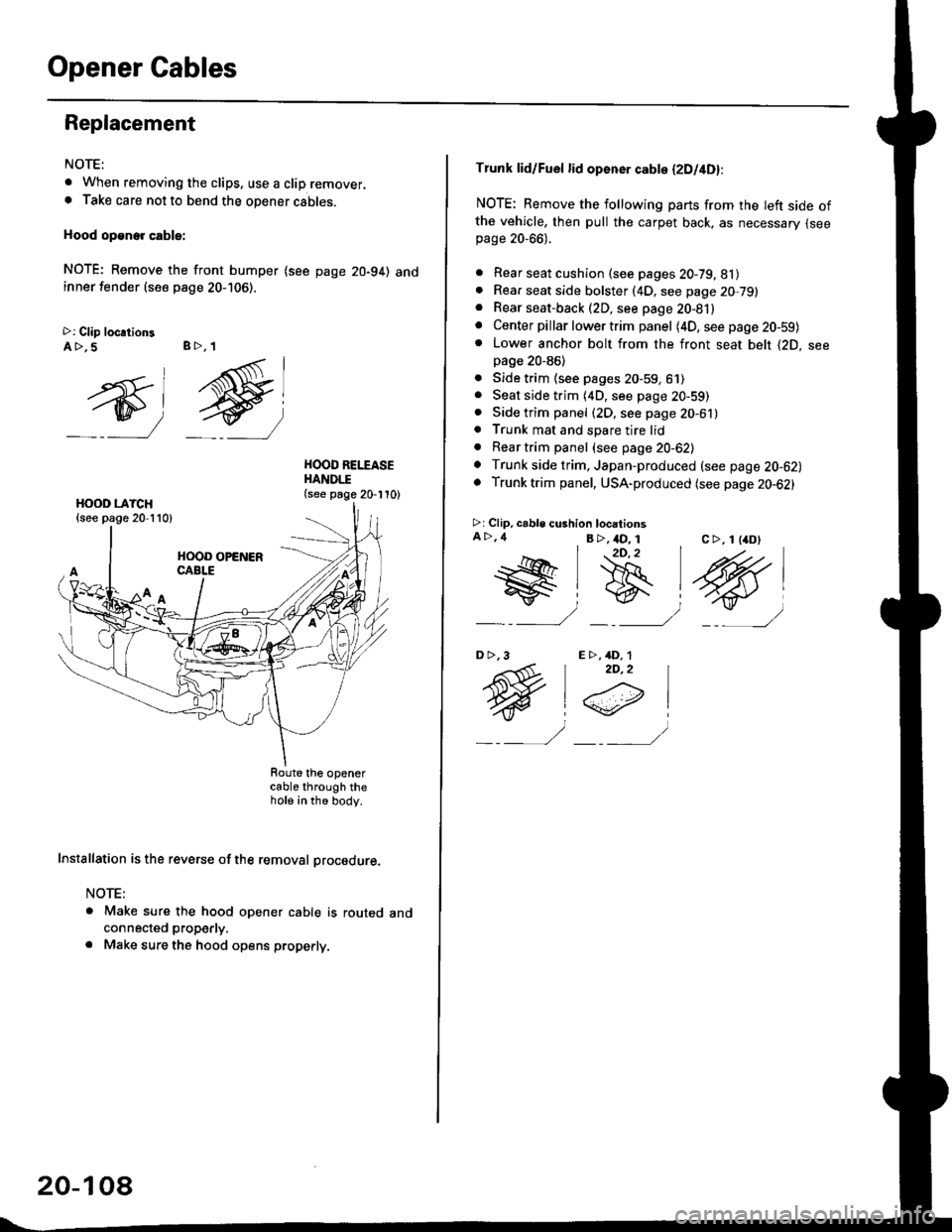
t When removing the clips. use a clip remover.. Take care not to bend the opener cables.
Hood op€ne. cable:
NOTE; Remove the front bumper (see page 20-94) andinner fender (see page 20-106).
>: Clip loc.tionsA >,5 B>, 1
ry)
g
HOOD REI.TASEHANDI.I(see page 20-110)
cable through thehote in th6 body.
Installation is the reverse of the removal procedure.
NOTE:
a Make sure the hood opener cable is routed andconnected properly.
. Make sure the hood opens properly.
20-10a
Tlunk lid/Fuel lid opener cabte (2Dl4D):
NOTE: Remove the following parts from rhe Ieft side ofthe vehicle, then pull the carpet back, as necessary {seepage 20-66).
. Rear seat cushion (see pages 20-79, 81). Rear seat side bolster (4D, see page 20,79). Rear seat-back (2D, see page 20-81). Center pillar lower trim panel (4D, seepage20-59)o Lower anchor bolt from the front seat belt {2D. seepage 20-86)
. Side trim (see pages 20-59, 61). Seat side trim (4D, see page 20-59). Side trim panel (2D, see page 20-61). Trunk mat and spare tire lid. Reartrim panel (see page 20-62). Trunk side trim, Japan-produced (see page 20-62). Trunk trim panel, USA-produced (see page 20-62)
>r Clip, cable cushion locationsA >,4 B >,4D_ 1c >, 1 l4D)2D,2
t@#lB
_ : _/ _-___)
E >,4D, 12D,2
@i
_ _,, -/
D>,3
Page 1340 of 2189

Opener CablesOpener and Latch
Replacement (cont'dl
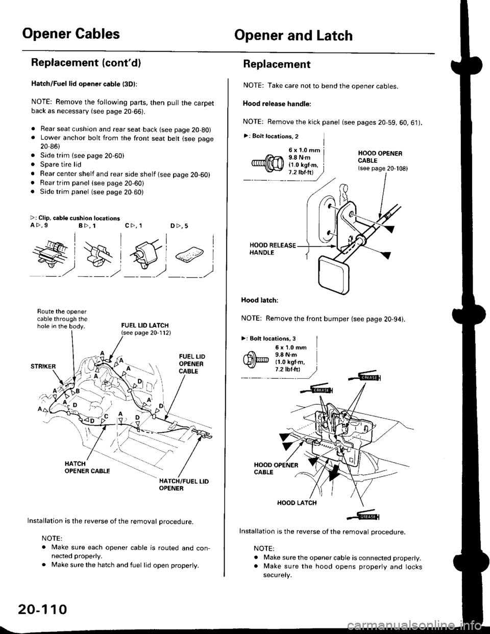
Hatch/Fuel lid opener cable l3Dl:
NOTE: Remove the following parts, then pull the carpetback as necessary (see page 20-66).
. Rear seat cushion and rear seat back (see page 20-80). Lower anchor bolt from the front seat belt (see page
20 86)
. Side trim {see page 20-60). Spare tire lid
. Rear center shelf and rear side shelf {see page 20-60). Rear trim panel (see page 20-60). Side trim panel (see page 20,60)
>: Clip, cable cushion locationsa>.9B>, 1c>, 1D >,5
W#)
FUEL LID LATCH
#,
Route the openercable through thehole in the body.
HATCH/FUEL LIOOPENER
Installation is the reverse of the removal procedure.
NOTE:
. Make sure each opener cable is routed and con-nected properly.
. Make sure the hatch and fuel lid open properly.
page 20-112)
20-110
6x1.0mm j9.8Nm{1.0 kgf.m, i
Replacement
NOTE: Take care not to bend the opener cables.
Hood release handle:
NOTE: Remove the kick panel (see pages 20-59, 60.61).
>: Bolt locations, 2 ]I
HOOO OPENERCABLE(see page 20-108)
Hood latch:
NOTE: Remove the front bumper (see page 20-94).
>: Eolt locations, 3 I6 x '1.0 mm9.8 N.m11.0 kgf.m,
Installation is the reverse of the removal procedure.
NOTE:
. Make sure the opener cable is connected properly.. Make sure the hood opens properly and locks
securely.