Page 1297 of 2189
Consoles/Console Panel
Replacement
NoTE:Takecarenottoscratchthefrontandrealconso|es,frontseatandre|atedparts.
Disassemble in numbered sequence
>: Screw locationsa>,8 B>,4>: Clip locationsA>,2 B>.2
' nnffir
:__)
"=)
:)
::r_l REAB CONSoLE(with armrest)
lnstallation is the reverse of the removal procedure
NOTE:
. lf necessary, replace any damaged clips.
. Make sure the wire harnesses are not pinched.
. Make sure the connector is connected properly.
€] FRONT CONSOLERemove the shift lever knob (M/T)
{.
I
I
20-67
Page 1298 of 2189
Dashboard
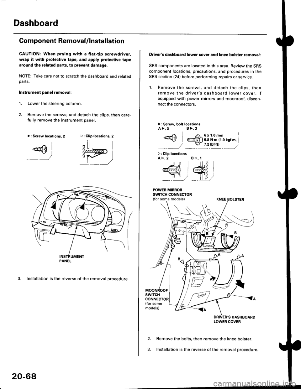
Component RemovaUlnstallation
CAUTION: When prying with a flat-tip screwdriver,
wrap it with protoctivo tape, and apply protective tape
around tho r6lat6d parts, to prevent damag6.
NOTE: Take care not to scratch the dashboard and relatedpans.
Instrument Danel removal:
1.Lower the steering column.
Remove the screws, and detach the clips, then care-
fully remove the instrument panel.
3. Installation is the reverse of the removal procedure.
>: Clip locations, 2
.il |
Pit)_ _ ,/
>: Screw locations,2
^l
@sl
:)
PANEL
20-68
Driver's dashboard lower cover and knee bolster removal:
SRS components are located in this area. Review the SRS
component locations, precautions. and procedures in the
SRS section (24) before performing repairs or service.
'1. Remove the screws, and detach the clips, then
remove the driver's dashboard lower cover. lf
equipped with power mirrors and moonroof, discon-
nect the connectors.
>: Screw, boh loc.tionsA>.3B>,2
_-rri I /a_6x1.0mm*\Y @{[) s 8 N'm tt o rst'm,
_-_- J _ \J- 7 2_rbtftl -_
>: Clip locationsA>.2 B >, 1
tu
DRIVER'S DASHBOARDLOWER COVER
Remove the bolts, then remove the knee bolster.
Installation is the reverse of the removal procedure.
Page 1300 of 2189
Dashboard
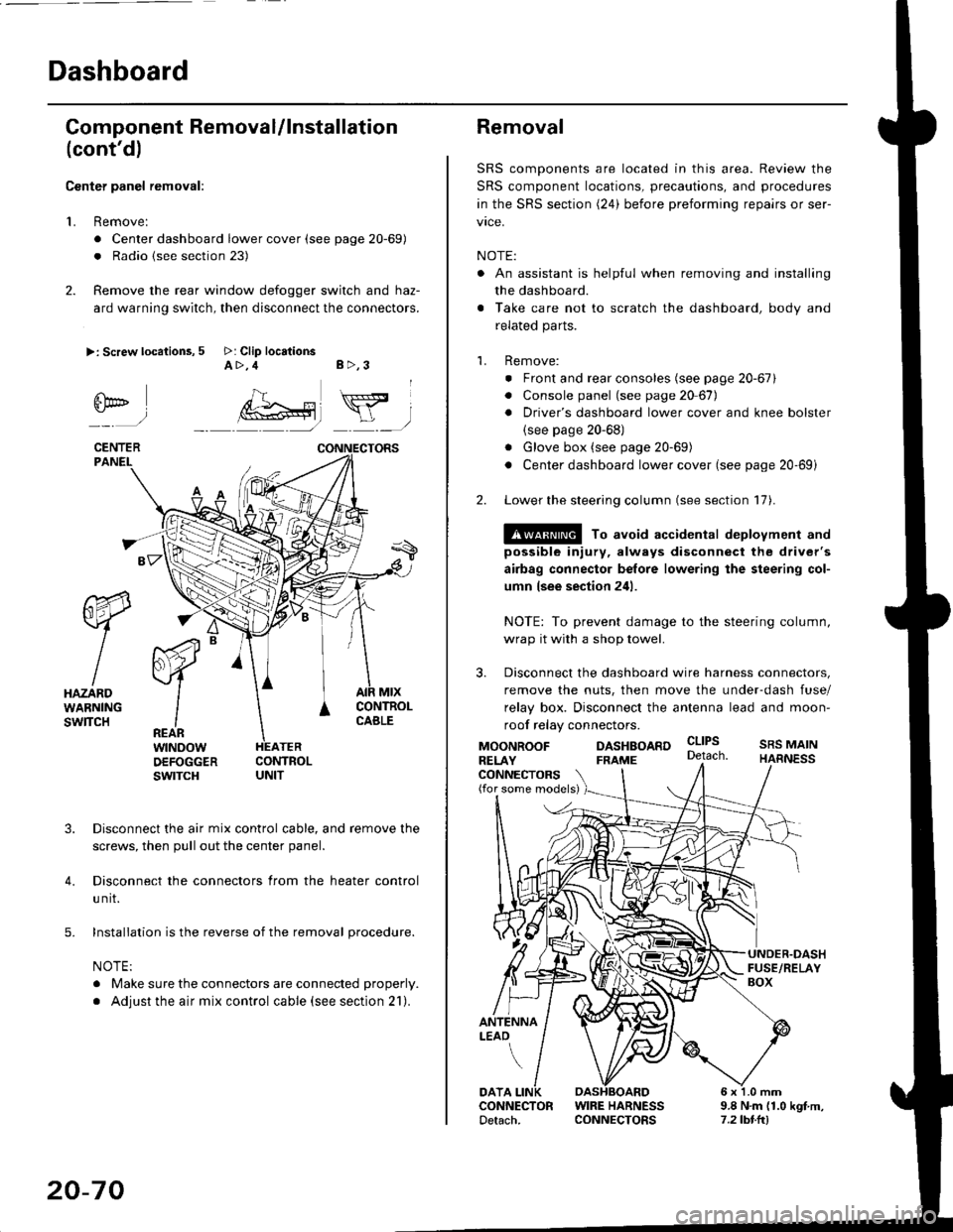
Gomponent Removal/lnstallation
(cont'd)
Center panel removal:
1. Remove:
. Center dashboard lower cover (see page 20-69)
. Radio {see section 23)
2. Remove the rear window defogger switch and haz-
ard warning switch, then disconnect the connectors.
>: Screw locations, 5 >: Clip locationsA>,4 B>,3
fii*-)
CENTERPANEI.
rt-xR.
W
IHAZARDWARNINGswlTcH
r44 "
F.IZvl
IIREARwtNoowOEFOGGERswtrcH
MtxCONTNOLCABLE
3. Disconnect the air mix control cable, and remove the
screws, then pull out the center panel.
4. Disconnect the connectors from the heater control
u nit.
5. Installation is the reverse of the removal procedure.
NOTE:
. Make sure the connectors are connected properly.
. Adjust the air mix control cable (see section 21).
20-70
Removal
SRS components are located in this area. Review the
SRS component locations, precautions, and procedures
in the SRS section (24) before preforming repairs or ser-
vice.
NOTE:
. An assistant is helpful when removing and installing
the dashboard.
. Take care not to scratch the dashboard, body and
related parts.
1. Remove:
o Front and rear consoles (see page 20-67)
. Console panel (see page 2O 67),
. Driver's dashboard lower cover and knee bolster(see page 20-68)
. Glove box (see page 20-69)
. Center dashboard lower cover (see page 20-69i
2. Lower the steering column (see section 17).
@ To avoid accidental deplovment and
possible injury, always disconnect the driver's
airbag connector belore lowering the steering col-
umn lsee section 241.
NOTE: To prevent damage to the steering column,
wrap it with a shop towel.
3. Disconnect the dashboard wire harness connectors,
remove the nuts, then move the under-dash fuse/
relay box. Disconnect the antenna lead and moon-
roof relay connectors.
DASHBOARD cltPs
CONNECTORS(for some models)
MOONROOFRELAY
ANTENNALEAO
FRAME
SRS MAINHARNESS
9.8 N.m (1.0 kgf m,7.2lbt.ltl
DATACONNECTOR WIRE HARNESSDetach. CONNECTORS
Page 1310 of 2189
Rear Seat
Removal (cont'dl
3D:
>: Bolt locationsA>,6
':^2
STRIKERRemove the side t.impanel (see page 20-60).
c>,1
STBIKER
,.:) : Hook locations, 2 >: Clip locations, 14
SEAT CUSHION
STRIKER
6x1.0mm9.8 N.m (1.0 kgI.m,7.2 tbf.ft)
V
RIGHTSEAT-BACK
Pivot bolt constiuction:
TOOTHEOLOCKWASHER
BUSHING
PIVOT
Installation is the reverse of the removal procedure.
NOTE:
Ptvor BoLT BRACKETI x 1.25 mm22 N.m {2.2 kgl.m. 16 lbf.ft)Apply liquid thread lock.
. Beiore anaching the seat-back and seat cushion, make sure there are no twists or kinks in the rear seat belts andcenter belt.
. When installing the seat cushion, slip the seat belt buckles through the slits in the seat cushion.. Make sure the seat-back locks securely.
. lf necessary, adjust the striker and seat-back.
20-ao
6xr.omm I9.8 N.m (1.0 ksf.h,i
@,
EE)qr ,/
6x1omm I22 N.m {2.2 kgf.m,l,"rrr,n2
PIVOTBRACKET
LEFTSEAT.BACK
tt
A
CENTERPIVOT
\---.---
6x1.0mm
BRACKET
B>, 1
e
I
tr
-l:/*- -"HOOK
Page 1315 of 2189
Front Seat Belt
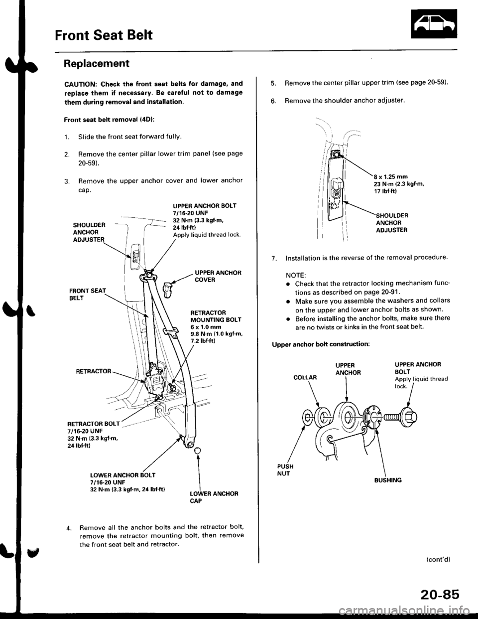
Replacement
CAUTION: Check the front seat belts for damage, and
replace them it necessary. Be carolul not to damage
them during removal and installation.
Front seat belt removal (4Dl:
1.Slide the front seat forward fully.
Remove the center pillar lower trim panel (see page
20-59).
Remove the upper anchor cover and lower anchor
cap.
SHOULDERANCHOR
UPPER ANCHOR BOLT7/16-20 UNF32 N.m (3.3 kgit m,24 lbf.ft)Apply liquid thread lock.
2.
3.
FRONT SEATBELT
RETRACTOR
RETRACTORMOUNTING BOLT6x1.0mm9.8Nm(1.0kgf.m.7.2 tbf.ftl
ER ANCHOR
Remove all the anchor bolts and the retractor bolt,
remove the retractor mounting bolt, then remove
the front seat belt and retractor.
1
I
ILOWCAP
7/1&20 UNF32 N.m (3.3 kgl.m.24 rbl.ftl
7/16-20 UNF32 N.m {3.3 kgf.m,24lbf.ft}
6.
8 x 1.25 mm23 N.m {2.3 kgt'm,17 tbf.ft)
ANCHORADJUSTER
7. Installation is the reverse of the removal procedure
NOTE:
. Check that the retractor locking mechanism func-
tions as described on page 20-91.
. Make sure you assemble the washers and collars
on the uDDer and lower anchor bolts as shown.
. Before installing the anchor bolts, make sure there
are no twists or kinks in the front seat belt.
Upper anchor boh construciion:
UPPER ANCHORBOLT
Remove the center pillar upper trim (see page 20-59)
Remove the shoulder anchor adjuster.
UPPER
COLLARApply liquid thread
(cont'd)
20-85
SUSHING
Page 1316 of 2189
Front Seat Belt
Replacement (cont'dl
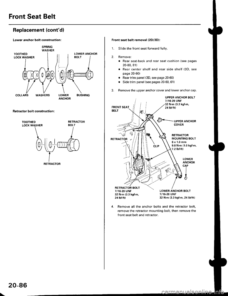
Lower anchor bolt construction:
SPRINGWASHER
COLLARSBUSHINGLOWERANCHOB
Retractor bolt construqtion :
TOOTHEDLocK W\HER
)rtnl
tv-
RETRACTORBOLT
I
llo1r",ffi)
\y
-"\s\,/
IRETBACTOF
LOWER ANCHOR
WASHEBS
\
20-86
Front seat belt removal (2Dl3Dl:
1. Sljde the front seat forward fully.
2. Removel
. Rear seat-back and rear seat cushion (see pages
20-80, 81)
. Rear center shelf and rear side shelf (3D. see
page 20'60)
. Rear trim panel (3D, see page 20-60)
. Side trim panel (see pages 20'60,61)
3. Remove the upper anchor cover and lower anchor cap.
UPPER ANCHOR BOLT7/16-20 UNF32 N.m (3.3 kgI.m,24 tbf.ftl
@<-'-.-.-.- ,PPER aNcHoR
RETRACTORMOUNTING BOLT6x1.0mm9.8 N.m (1.0 kgt m,7.2 tbtft)
LOWER ANCHOR BOLT7/16-20 UNF32 N.m (3.3 kgl m, 24lbtft)
LOWEBANCHORCAP
IIto
4. Remove all the anchor bolts and the retractor bolt,
remove the retractor mounting bolt, then remove the
front seat belt and retractor.
RETRACTOR BOLT7/16-20 UNF32 N m 13.3 kgf m,24 tbf.ftl
Page 1318 of 2189
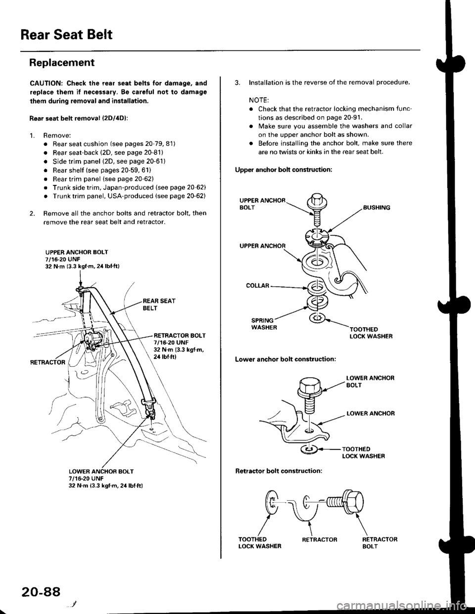
Rear Seat Belt
Replacement
CAUTION: Chack the rear seat belts for damage, and
replace them if necessary, 8e carolul not to damage
lhem during removal and installation.
Rear seat belt removal {2Dl4D}:
1. Remove:
. Rear seat cushion (see pages 20-79, 81)
. Rear seat-back (2D, see page 20-81)
. Side trim panel (2D, see page 20-61)
. Rear shelf (see pages 20-59,61)
. Rear trim panel {see page 20-62}
. Trunk side trim, Japan-produced (see page 20-62)
. Trunk trim panel, USA-produced (see page 20-62)
2. Remove all the anchor bolts and retractor bolt, then
remove the rear seat belt and retractor.
UPPER ANCHOR BOLT7/16-20 UNF32 N.m (3.3 kgf.m,2,1 lbtft)
RETNACTOR BOLT7/1F20 UNF32 N.m {3.3 kgf.m,24 tbt.ft)
7/16-20 UNF32 N.m {3.3 kgf.m,24lbt.ft)
20-88
R€TRACTOB
3. Installation is the reverse of the removal procedure.
NOTE:
. Check that the retractor locking mechanism func-
tions as described on page 20-91.
. lvlake sure you assemble the washers and collar
on the upper anchor bolt as shown.
. Before installing the anchor bolt. make sure there
are no twists or kinks in the rear seat belt.
Upper anchor boh condruqtion:
SPRINGWASHER
Lower anchor bolt construction:
LOWER ANCXOREOLT
LOWER ANCHOR
Retractor bolt construction:
RETRACTORBOLT
t7 /7--^,l/rn .----. A -nrfi|lH \
tr\7-\
/\TOOTHEDLOCK WASHER
Page 1319 of 2189
Rear seal belt removal (3Dl:
1. Remove:
. Rear seat-back and rear seat cushion (see page
20_80)
. Rear center shelf and rear side shelf (see page
20_60)
. Rear trim panel and side trim panel (see page 20
60)
2. Remove the upper anchor cover
UPPER ANCHOR BOLT7/16-20 UNF32 N.m {3.3 kgf.m,2it lblft)
UPPERANCHOR
RETRACTOR
RETRACTOR BOLT7/16-20 UNF32 N.m 13.3 kgl.m.24 tbf.ft)
REAR SEATBELT
LOWEF
3.
7/r6-20 UNF32 N.m {3.3 kgl.m. 24 lbf.ftl
Remove all the anchor bolts and retractor bolt. then
remove the rear seat belt and retractor.
4. Installation is the reverse of the removal procedure.
NOTE:
. Check that the retractor locking mechanism func
tions as described on page 20-91.
. Make sure you assemble the washers and collars
on the upper anchor bolt as shown.
. Betore installing the anchor bolt, make sure there
are no twists or kinks in the rear seat belt.
Upper snchor boh construction:
COLLARS
Lower anchor bolt construction:
LOWER ANCHOR
TOOTHEDLOCK WASHER
(cont'd)
20-89