Page 1247 of 2189
bOuter Handle Replacement
NOTE: Raise the glass fully.
1. Remove:
. Door panel
. Plastic cover (see page 20-14)
2. Pull out the retainer clip.
3.e\
CYLINOER PROTECTOR
LOCK CYLINDER
RETAINERCLIP
Remove the bolts, then remove the cylinder protec-
tor, lock cylinder and outer handle.
>: Bolt locations,2
6x1.omm ]9.8 N.m {1.0 kgf.m,1.2tbl,ttl )_, _-_-,/
CYLINDERPROTECTOR
LOCK CYLINOER
CYLINOER ROD
20-17
4. Pull out the outer handle. Pry the outer handle rod
out of its joint using diagonal cutters.
NOTE:
. To ease reassembly, note location @ ot the outer
handle rod on the joint before disconnecting it.
. Take care not to bend the outer handle rod.
. Use a shop towel to protect the opening in the
door.
DIAGONALCUTTERS
SHOPTOWEL
5. Installation is the reverse of the removal procedure.
NOTE: Make sure the door locks and opens properly.
EUSHINGReplace.
\
,pr,
Page 1248 of 2189
Doors
Latch Replacement
NOTE: Raise the glass fully.
1. Remove:
. Door panel (see page 20-16)
. Plastic cover (see page 20-14). Outer handle {see page 20-17}
2. Remove the rod protector.
LATCH
PROTECTOR
20-18
3. Remove the bolts and move the center lower channel.
NOTE: Take care not to bend the inner handle rod
and lock rods.
>: Screw locations
A>,38>,3
q)
CENTER LOWEBCHANNEICBANKHOLDER
Disconnectthe connector,
6x1.0mm8 N.m 10.8 kgt.m,6 tbtft)
Remove the inner handle, then remove the latch
through the hole in the door.
lnstallation is the reverse of the removal procedure.
NOTE: Make sure the door locks and opens properly.
5.
6x1.0mm l
ffu 6 N.m {0.6 kef.m,
_" 11111 )
Page 1249 of 2189
LGlass/Regulator Replacement
2.
1.Remove:
. Door panel (see page 20-'16)
. Plastic cover (see page 20-14)
Carefully move the glass until you can see the bolts,
then loosen them. Slide the guide rearward, remove
the glass trom the guide, and carefully pull the
glass out through the window slot.
NOTE: Take care not to drop the glass inside the door.
>: Bolt localions,2
6x1.0mm
E 9.8 N.m {1.0 kgtm, Il* 7.2 tbrfil I\3 Loosen ,/
Jt
GUIDE
3. Disconnect the connector, and detach the harness
clip, then remove the regulator through the hole in
the door.
NOTE: Scribe a line around the rear roller guide bolt
to show the original adjustment.
>: Bolt locations
a >,4
6xL0mmI6x1.omm II N.m {0.8 kgt.m,6lbrft ]Loosen. ,/
B >,2
8 N.m (0.8 kgt m, i'-1
)
ROLLERREGULATOR
BOLTS
(cont'd)
20-19
Page 1250 of 2189

Doors
Glass/Regulator Replacement (cont'dl
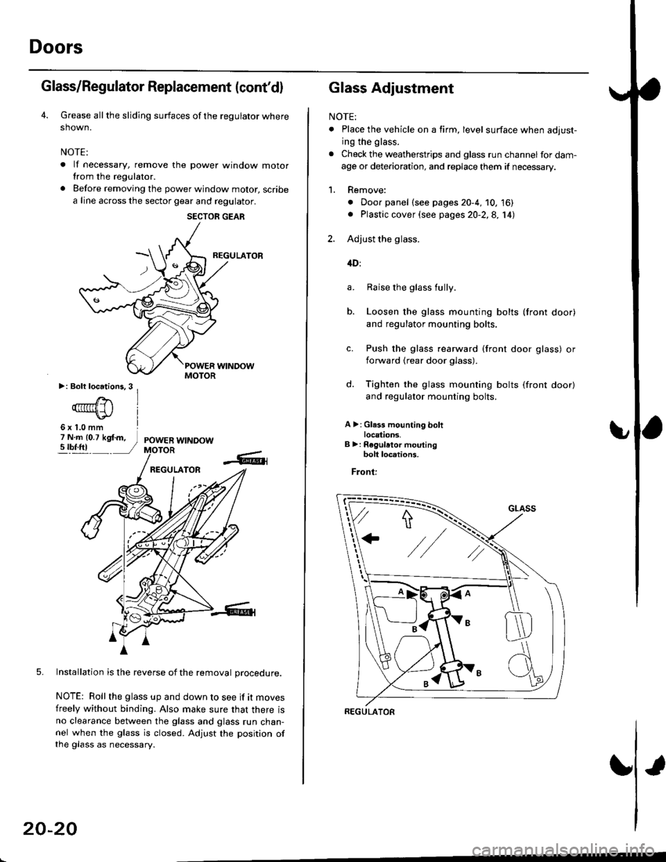
Grease all the sliding surfaces of the regulator where
shown.
NOTE:
. lf necessary, remove the power window motorfrom the regulator.
. Before removing the power window motor, scribe
a line across the sector gear and regulator.
REGULATOR
5. Installation is the reverse of the removal orocedure.
NOTE: Roll the glass up and down to see if it moves
freely without binding. Also make sure that there isno clearance between the glass and glass run chan-nel when the glass is closed. Adjust the position ofthe glass as necessary.
SECTOR GEAR
20-20
Glass Adjustment
NOTE:
. Place the vehicle on a firm, level surface when adjust-
ing the glass.
. Check the weatherstrips and glass run channel for dam-
age or deterioration, and replace them if necessary.
1. Remove:
. Door panel (see pages 20-4, 10, 16). Plastic cover (see pages 20-2,8, 14)
2. Adjust the glass.
4D:
Raise the glass fully.
Loosen the glass mounting bolts (front door)
and regulator mounting bolts.
Push the glass rearward (front door glass) or
iorward (rear door glass).
Tighten the glass mounting bolts (front door)
and regulator mounting bolts.
A >: Gl.3s mounting boltlocations.B >: Regulrtor moutingbolt loc.tions.
Front:
a.
b.
d.
REGULATOR
Page 1252 of 2189
Doors
Glass Adjustment {cont'd)
c. Tighten the roller guide bolts.
d. Loosen the front channel bolts.
e. Lower the glass.
f. Push the front channel against the glass, then
tighten the mounting bolts.
MOUNTINGBOLT
3. Check that the glass moves smoothly.
4. Raise the glass fully and check for gaps.
5. Check the glass operation.
NOTE: Check that the glass contacts the glass run
channel evenly.
WEATHERSTRIP
GLASS
U
-\,
20-22
6. Check for water leaks.
Spray water over the roof and on the sealing area
as shown.
NOTE:
. Adjust the water pressure as shown.
. Do not squeeze the tip of the hose.
0.5 m {1.6ft)
HOSE
Attach the plastic cover, then install the door panel
(see pages 20 4, 10, 16).
Install the regulator handle so it points forward and
up at a 45 degree angle with the glass closed.
Forward -
1.
HOSE
300 mm {11.8 in)
Page 1254 of 2189
Mirrors
Mirror Replacement
NOTE: Take care not to scratch the mirror. mirror basecover and door.
l� Lower the door glass.
2. Carelully pry out the mirror mount cover panel bynano.
Power mirro.:
MIRROR MOUNTCOVEB PANEL
Manual mirror:
Remove the cap, screw and knob, then remove themirror mount cover panel.
MIRROR MOUNT
KNOB
20-24
3. Remove the mirror mounting nuts while supporting
the mirror.
a: Nut locations,3
€)CONNECTOR(Nrirror side)
MIRROR
(Door harnessside)
CONNECTOR
Installation is the reverse of the removal procedure.
NOTE: Make sure the connector is connected prop-
erly.
Page 1262 of 2189

Rear Window
Removal
2DllDl
CAUTION:
. Put on gloves to protect your hands.
. Uso ssat covers to avoid damaging any surlaces,. Do not damage thg roar window dofogggr grid linss,
window antenna grid lines, and tsrminalg.
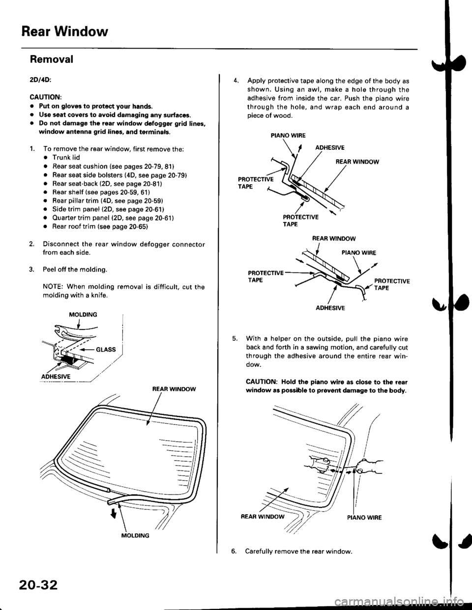
1. To remove the rear window, first remove the:. Trunk lid
. Rear seat cushion (see pages 20-79, 81). Rear seat side bolsters {4D, see page 20-79). Rear seat-back (2D, see page 20-81)
. Rear shelf {see pages 20-59, 61}
. Rear pillar trim {4D, see page 20-59). Side trim panel (2D, see page 20-61)
. Ouarter trim panel (2D, see page 20-61)
. Rear roof trim (see page 20-65)
2, Disconnect the rear window defogger connector
from each side.
3. Peel off the molding.
NOTE: When molding removal is difficult, cut the
molding with a knile.
F"*t,
MOLDING
ID_HESI.VE ---, ,/,/
REAR WINDOW
S
MOLDING
20-32
PIANO WIRE
4. Apply protective tape along the edge of the body as
shown. Using an awl, make a hole through the
adhesive from inside the car. Push the piano wire
through the hole, and wrap each end around apiece of wood.
ADHESIVE
REAR WINDOW
PROTECTIVETAPE
TAPE
REAR WNDOW
PIANO WIRE
PROTECTIVETAPE
With a helper on the outside, pull the piano wire
back and forth in a sawing motion, and carefully cut
through the adhesive around the entire rear win-
dow.
CAUTION: Hold the piano wiro as close to the rear
window as possibls to prcyent damage to the body.
6. Carefullv remove the rear window.
ADHESIVE
Page 1266 of 2189

Rear Window
Removal
3D:
CAUTION:
. Put on gloves to ptotect your hands.. Us€ seat cove6 to avoid damaging any surfaces.. Do not damage the rear window defogger grid lines.. Take carg nol scratch the terr window molding.
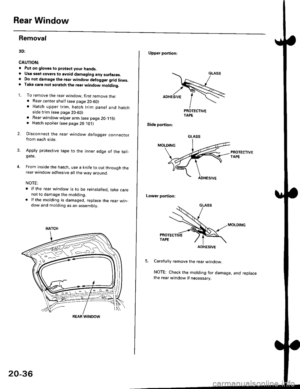
'1. To remove the rear window, firsr remove the:. Rear center shelf (see page 20-60). Hatch upper trim, hatch trim panel and hatchside trim (see page 20-63)
2.
. Rear window wiper arm (see page 2O-115). Hatch spoiler (see page 20 101)
Disconnect the rear window defogger connectorfrom each side.
Apply protective tape to the inner edge of the tail_gate.
From inside the hatch, use a knife to cut through therear window adhesive all the way around.
NOTE:
. lf the rear window is to be reinstalled, take carenot to damage the molding.. lf the molding is damaged, replace the rear win_dow and molding as an assembly.
HATCH
ffi#
REAR WINOOW
20-36
Upper portioni
TAPE
Side portion:
Lower portion;
Carefully remove the rear window.
NOTE; Check the molding for damage, and replacethe rear window if necessary.
GLASS
ADHESIVE