1999 HONDA CIVIC Clutch installation
[x] Cancel search: Clutch installationPage 72 of 2189

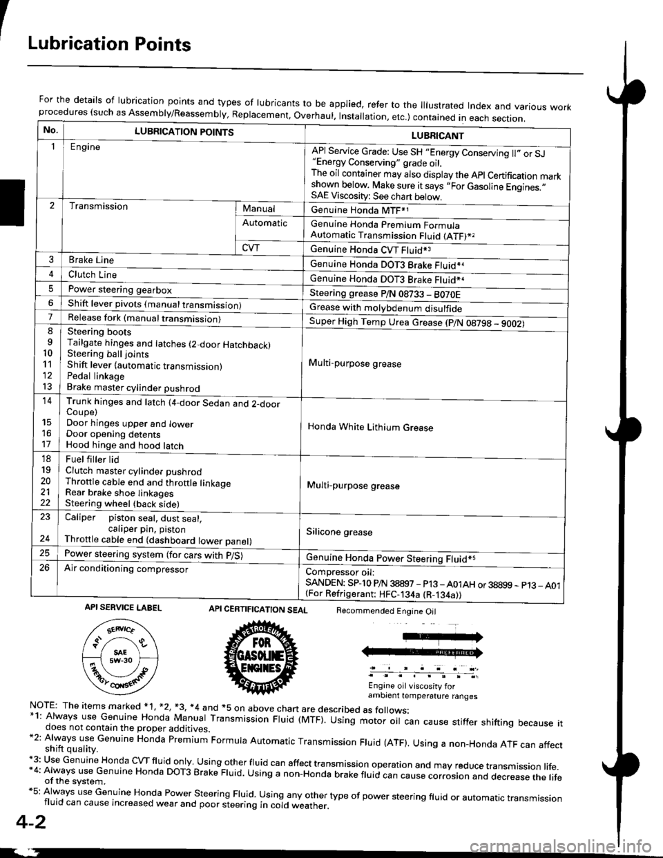
ILubrication Points
For the details of lubrication points and types of lubricants to be applied, refer to the lllustrated Index and various workprocedures (such as Assembly/Reassembly, Replacement, Overhaul. Installation, etc.) contained in each section.
No.LUBRICATION POINTS
Engine
LUBRICANT
"Energy Conserving" grade oil,The oil container may also display the Apl Certification markshown below. Make sure it says ,,For Gasoline Engines.,,SAE Viscosity: See chart below,
I
TransmissionManualGenuine Honda MTF*1
Genuine Honda Premium FormulaAutomatic Transmission Fluid (ATF)*,
Genuine Honda CVT Fluid*3
Genuine Honda DOT3 Brake Fluid*a
Automatic
CVT
3Brake Line
ClL,tci t""e4
I
Genuine Honda DOT3 Brake Fluid*aPower steering gearboxSteering grease P/N 08733 - BO70EShift lever pivots (manual transmission)Grease with molybdenum disulfide7-:ti
9
10'l'l
l3
14
't7
18
19
20
2122
Release fork (manual trancmi
Shift lever (automatic transmission)Pedal linkageBrake master cylinder pushrod
Super High Temp Urea crease (p/N 08798 - 9OO2)
i Multi-purpose grease
I
I
Honda White Lithium Grease
Multi-purpose grease
Silicone grease
@
Trunk hinges and latch (4-door Sedan and 2-doorCoupe)Door hinges upper and lowerDoor opening detentsHood hinge and hood latch-FUet T ter ttd
Clutch master cylinder pushrodThrottle cable end and throttle linkageRear brake shoe linkagesSteering wheel (back side)
23
E-
Caliper piston seal, dust seal,caliper pin. pistonThrottle cable end (dashboard lower panel)
Power steering system (for cars with p/S)
Air conditioning compressorComDressor oil:SANDEN: SPlo P/N 38897 - p13 -A01AH or 38899 - p13_ A01{For Refrigerant: HFC-134a (R-134a))
CERTIFICATION SEAL
ffi
NorE: The items m arked * 1, *2, +3, *4 and +5 on above chan are described as folows:*1: Always use Genuine Honda Manual Transmission Fluid (MTF). Using motor oil can cause stiffer shifting because itdoes not contain the proper additives.*2: Always use Genuine Honda premium Formula Automatic Transmission Fluid (ATF). Using a non-Honda ATF can affectshift quality.+3: Use Genuine Honda cVTfluid only usingotherfluid can affect tra nsmission operation and may reduce transmission life.*4: Always use Genuine Honda DoT3 Brake Fluid. Using a non-Honda brake fluid can cause corrosion and dec.ease the lifeof the svstem.*5: Always use Genuine Honda Power steering Fluid. using any other type of power steering fluid or automatrc transmissionfluid can cause increased wear and poor steering in cold weather.
4-2
Recommended Engine Oil
Engine oil viscosity forambrent temperature ranges
API SERVICE LABEL
Page 570 of 2189

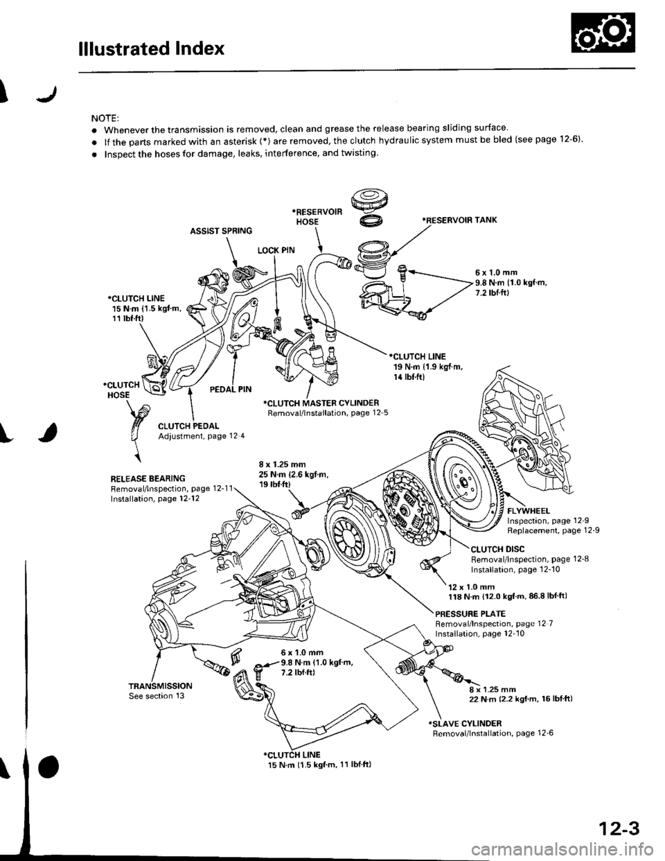
lllustrated Index
\
NOTE:
. Whenever the transmission is removed, clean and grease the release bearing sliding surface
. lf the parts marked with an asterisk (*) are removed, the clutch hydraulic system mustbe bled (seepage 12-6)
. Inspect the hoses for damage, leaks, interference, and twisting
'RESERVOIF TANK
ASSIST SPRING
LOCK PIN
5x1,0mm9.8 N.m (1.0 kgf.m,7.2 tbtftl*CLUTCH LINE15 N.m {1.5 kgJ m,11 tbt.ft)
RELEASE BEARINGRemoval/lnspection, page 12-1 1Installation, page 12-'12
*CLUTCH MASTER CYLINDERRemoval/lnstallation, page 12 5
6x1.0mm9.8 N.m (1.0 kgf.m,7.2 tbf.ft)
FLYWHEELInspectaon, page 12IReplacement, Page 12-9
CLUTCH DISCRemoval/lnspection, page 1 2-8
lnstallation, page 12-'10
'12 x 1.0 mm118 N.m {12.0 kgt'm,86.8lbfft)
PBESSURE PLATEBemoval/lnspection, page 12 7Installation, page 12''10
8 x 1.25 mm22 N m (2.2 kgf.m, 16lbf ft)
ISLAVE CYLINDERRemoval/lnstallation, page 12_6
12-3
Page 577 of 2189

FlywheelClutch Disc, Pressure Plate
Replacement (cont'dl
4. Drive the new ball bearing into the flywheel using
the special tools as shown.
DRIVER07749-0010000
ATTACHMENT,32x35mm07746-OOIOTOO
FLYWHEEL
BEARING
Align the hole in the flywheel with the crankshaft
dowel pin and install the flywheel. Install the
mounting bolts finger-ti9ht.
Install special tool, then torque the flywheel mount-
ing bolts in a crisscross pattern in several steps as
snown.
5.
6.
MOUNTING BOLTS118 N.m (12.0 kgl.m,87 tbf.ft)
RING GEAR HOLDER07LAB-PV00100ol07924 -PO20003
WVa// ,
12-10
Installation
1. Install the special tool.
Y
07936-3710r00
{P/N 08798-90021
RING GEAR HOLDER07LAB-PVOO100ot07924-PD20003
CLUTCH ALIGNMENT SHAFTOTJAF_PM7012A
2.
3.
Installthe clutch disc using the special tools.
Install the pressure plate.
RING GEAR HOLDERoTLAB PV00'l OO
07924 PD20003
OTJAF_PM70124HANOLE07936-3710100
CLUTCH DISC
Page 579 of 2189

Release Bearing
Installation
NOTE: Use only Super High Temp Urea Grease(P/N 08798 - 9002).
1. With the release fork slid between the release bear-
ing pawls, install the release bearing on the main-
shaft while inserting the release fork through the
hole in the clutch housing.
RELEASE FORK BOLT12 x 'l .25 mm
tP/N 0a79a-90021O.3-0.9 s 10.01 -O.03 ozl
Align the detent of the release fork with the release
fork bolt, then press the release fork over the
release fork bolt sequarely.
-Gr08798-9002)
2.
12-12
IJ
3. Move the release fork right and left to make surethat it fits properly against the release bearing, and
that the release bearing slides smoothly.
4. Install the release fork boot; make sure the bootseals around the release fork and clutch housino.
Page 588 of 2189

Transmission Assembly
Removal(cont'd)
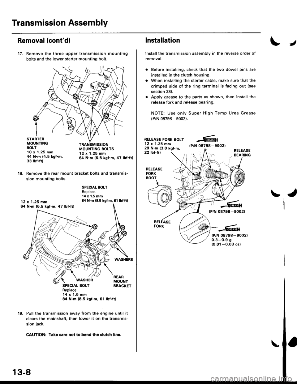
17. Remove the three upper transmission mounting
bolts and the lower starter mounting bolt,
STARTERMOUNTINGBOLT10 x 1.25 mm44 N.m (4.5 kgf.m,33 rbnftl
TRANSMISSIONMOUI{TING EOLTS12 x 1.25 mm& N.m (6.5 kgt'm,47 lbl.ftl
18. Remove the rear mount bracket bolts and transmis-
sion mounting bolts.
12 x 1.25 mm64 N.ft 16.5 kgl.m,47 lbl.ftl
SPECIAL BOLTReplace.'ll x 1.5 mm84 N.m (8.5 kgf.m, 61 lbf.ftl
SPECIAL BOLTReplace.14 x 1,5 mln84 N.m (8.5 kgl.m, 61
WASI{ERREARMOUNTBRACKET
rbl.ftt
Pull the transmission away from the engine until it
clears the mainshaft. then lower it on the transmis-
sion jack.
CAUTION: Take caro not to b6nd tho clutch lin€.
1(|
Installation
Install the transmission assembly in the reverse order of
removal.
Before installing, check that the two dowel pins are
installed in the clutch housing.
When installing the starter cable, make sure that the
crimped side of the ring terminal is facing out (see
section 23).
Apply grease to the parts as shown, then install the
release fork and release bearing,
NOTE: Use only Super High Temp Urea Grease
(P/N 08798 - 9002).
RELEASE FORK BOLT12 x 1.25 mm29 N'm 13.0 kgt,m,(P/N 08798-90021
22 tbl.ttlR€LEASEBEARING
J
RELEASEFORK8()07
ra
{PiN 08798-9002)
tP/N 08798-900210.3-0.9 g
10.01-0.03 ozl
Page 617 of 2189

70 mm THRUST SHIM: Dl6Y5, Dl6Y8 engin€s
Part NumberThickness
23931 - PL3 - 8000.60 mm 10.0236 in)
23932-PL3-8000.63 mm (0.0284 in)
c23933-PL3-8000.66 mm (0.0260 in)
D23334-PL3-8000.69 mm 10.0272 in)
E23935-PL3-8000.72 mm (0.0283 in)
F23936 - PL3 8000.75 mm (0.0295 in)
23937-PL3-B000.78 mm (0.0307 in)
23938-PL3-8000.81 mm (0.0319 inl
23939-PL3-8000.84 mm (0.0331 in)
23940-PL3-8000.87 mm {0.0343 in)
23941 - PL3 - 8000.90 mm (0.0354 in)
L23942-PL3-8000.93 mm (0.0366 in)
23943-PL3-8000.96 mm (0.0378 in)
N23944-PL3-8000.99 mm i0.0390 in)
o2394s-PL3-8001.02 mm (0.0102 in)
P23946-PL3-8001.05 mm {0.0413 in}
o23947-PL3-8001.08 mm (0.0{25 in)
23948 - PL3 800'1.1'1 mm (0.0437 4n)
23949-PL3-8001.14 mm (0.0449 inl
T23950-PL3-8001.17 mm (0.0461 in)
23951 - PL3 - 8001.20 mm (0.0472 in)
23952-PL3-8001.23 mm (0.0444 in)
239s3-PL3-8001.26 mm {0.0496 in)
X23954-PL3-8001.29 mm (0.0508 in)
2395s-PL3-8001.32 mm (0.0520 in)
z23956-PL3-8001.35 mm (0.0531 in)
23957-PL3-8001.38 mm (0.0543 in)
A823958-PL3-8001.41 mm (0.0555 in)
AC23959-PL3-8001.44 mm {0.0567 in)
AD23960-PL3-8001.47 mm (0.0579 in)
2396'�t-PL3-8001.50 mm (0.0591 in)
23962-PL3-8001.53 mm (0.0602 in)
AG23963-PL3-8001.56 mm (0.0614 in)
AH23964-PL3-8001.59 mm (0.0626 in)
23965-PL3-8001,62 mm (0.0638 in)
23966-PL3-8001.65 mm (0.0650 in)
AK23967-PL3-8001.68 mm (0.0661 in)
23968-PL3-8001.71 mm (0.0673 in)
23969-PL3-8001.74 mm (0.0685 in)
AN23970-PL3-8001.77 mm (0.0697 in)
AO23971- PL3 8001.80 mm (0.0709 inl
6. Installthe oil guide plate and selected thrust shim in
ths transmission housing
NOTE:
. Clean the thrust washer, spring washel and
thrust shim thoroughly belore installation.
. lnstall the thrust washer, spring washer and
thrust shim proPerlY.
THRUST SHIM
I
OIL GUIDEPLATE
TRANSMISSIONHOUSING
8.
o
10.
7, Install the thrust washer and spring washer in the
mainshaft.
lnstall the mainshaft in the clutch housing
Place the transmission housing over the mainshaft
and onto the clutch housing.
Tighten the clutch and transmission housings with
several 8 mm bolts.
NOTE: lt is not necessary to use sealing agent
between the housings'
8 x 1.25 mm
27 N'm t2.8 kgf.m. 20 lbf'ft)
Tap the mainshaft with a plastic hammer.
Check the thrust clearance in the manner doscribsd
below.
CAUnON: Mc.suromont 3hould bo mlde !t room
tomp9laturs.
a. Slide the mainshaft base and the collar over the
mainshaft.
CLUTCHHOUSING
11.
lz.
MAITISHAFT BASE07GAJ-PG20130COLLAF07GAJ -PG20120
{cont'd}
13-37
THRUST WASHER
SPRING WASI{ER
Page 625 of 2189

S4C Model ('99 - 00 2-door Si, SiR)
Manual Transmission
Special Tools ............' 13-46
Maintenance
Transmission Oi1 ...................'.......... 13-47
Back-up Light Switch
Repfacement ...""" 13'47
Transmission Assembly
Removal ......'.......... 13-/tB
lnstallation ............. 13-52
lllustrated lndex ................................... 13-54
Transmission Housing
Removal ................. 13-55
Beverse Shift Holder, Reverse ldler Gear
Clearance lnspection ...................".. 13-57
Removal ................. 13-58
Change Holder Assembly
Clearance lnspection .................".... 13-59
Removal ....,,........... 13-61
Disassembly/Reassembly ............... 1 3-62
Mainshaft, Countershaft, Shift Fork
Removal ................. 13-63
Shift Rod
Removal .........."'.... 13-64
Shift Fork Assembly
lndex ................ ...... 13-65
Clearance lnspection .............'......... 13'66
Mainshaft Assembly
lndex ............"" ...... 13-67
Clearance lnspection ....................... 13-68
Disassembly .......... 13-71
fnspection '."'.......', 13'72
Reassembly .......'... 13-73
Countershaft Assembly
fndex ................ "....13-71
Glearance Inspection'......'...........'... 1 3'75
Disassembly .......... 13-76
fnspection .'............13'77
Reassembly "......... 13'78
Synchro Sleeve, Synchro Hub
Inspection .............. 13'8C
Installation ............. 13-80
Synchro Ring, Gear
Inspection .'............ 13-81
Differential
lndex ................ ...... 13-82
Backlash Inspection ..."..........."'...... 1 3-82
Final Driven Gear Replacement ...... 13-83
Bearing Replacement ....."'.......""'.. 13-83
Thrust Shim Adiustment ......""'..... 13-84
Clutch Housing Bearing
Replacement ..'...... 13-86
Mainshaft Thrust Glearance
Adiustment '.........'. 13-88
Transmission
Reassembly ."'....... 13-91
Oil Seals
Replacement ..'...... 13-96
Gearshift Mechanism
Overhaul ................ 13-97
\
Page 669 of 2189

72 mm Thrust Shim
t
Part NumberThickness
23931 - P21 0000.60 mm {0.0236 in}
23932-P21 -0000.63 mm 10.0248 in)
c23933 P21 - 0000.66 mm (0.0260 in)
D23934 - P21 0000.69 mm (0.0272 in)
E2393s-P21-0000.72 mm (0.0283 in)
F23936-P21 -0000.75 mm (0.0295 in)
G23937 -P21-O000.78 mm (0.0307 in)
23938-P21 -0000.81 mm (0.0319 in)
23939-P21 -0000.84 mm (0.0331 in)
J23940-P21 -0000.87 mm (0.0343 in)
K23941 P21 - 0000.90 mm (0.0354 ini
L23942 - P21 0000.93 mm (0.0366 in)
23943-P21 -0000.96 mm 10.0378 in)
N23944 - P21 -0000.99 mm (0.0390 in)
o23945 - P21 0001.02 mm (0.0402 in)
P23946 - P21 0001.05 mm (0.0413 in)
o23947 - P2l 0001.08 mm (0.0425 in)
R23948-P21 -0001.'1 'l mm (0.0437 in)
S23949 - P21 0001.14 mm (0.0449 in)
T23950 - P21 0001.17 mm (0.0461 in)
23951 - P21 -0001.20 mm (0.0472 in)
23952 - P21 -0001.23 mm (0.0484 in)
23953-P21 -0001.26 mm (0.0496 in)
X23954-P21 -0001.29 mm (0.0508 in)
23955 - P21 -0001.32 mm (0.0520 in)
z23956-P21 -0001.35 mm (0.0531 in)
23957-P21 -0001.38 mm 10.0543 in)
AB23958 - P21 -0001.41 mm (0.0555 in)
AC23959 P21 - 0001.44 mm {0.0567 in)
23960 - P21 0001.47 mm (0.0579 in)
AE23961 - P21 -0001.50 mm {0.0591 in)
23962 P21 - 0001.53 mm {0.0602 in)
AG23963-P21 -0001.56 mm (0.0611in)
AH23964-P21 -0001.59 mm {0.0626 in)
23965-P21 -000'1.62 mm {0.0638 in)
23965-P21 - 0001.65 mm (0.0650 in)
AK23967-P21 -0001.68 mm {0.0661 in)
23968 - P21 -0001.71 mm 10.0673 in)
23969 P21 - 0001.74 mm {0.0685 in)
AN23970-P21 -0001.77 mm {0.0697 in)
AO23971 - P21 -0001.80 mm (0.0709 in)
7. lnstallthe thrust shim selected and oil guide plate in
the transmission housing.
72 mm THRUSTOIL GUIDE PLATE
TRANSMISSIONHOUSING
8. Install the spring washer and washer on the ball
beaflng.
NOTE:
. Clean the spring washer, washer and thrust shim
throughly before installation.
. Install the spring washer, washer and thrust
shim properlY.
-WASH€R-<]>-.-'
x -sPRtNG WASHER
-.-sK((9r'
lnstallthe mainshaft in the clutch housing.
Place the transmission housing over the mainshaft
and onto the clutch housing.
Tighten the clutch and transmission housings with
several 8 mm bolts.
NOTE: lt is not necessary to use sealing agent
between the housings.
8 x 1.25 mm
27 N.m (2.8 kgf.m. 20 lbf'ft)
Tap the mainshaft with a plastic hammer.
(cont'd)
9.
10.
'I l.
12.
13-89