Page 1471 of 2189

l'f .
Electrical
Special Toofs .,....................,23-2
Troubleshooting
Tips and Precautions ..............,.................... . 23-3
Five-step Troubleshooting .............. ......... . . 23-5
wire color codes ..........,23-5
Schematic Symbols ........,................... . . .. .... 23-6
Relay and Control Unit Locations
Engine Compartment ...,..................... ... .. . 23'7
Dashboard ......................23-8
Dashboard/Door ......... 23-12*Airbags ................. ....... Section 24
Air Conditioning ......... Section 21
Aftelnator ..........."""" """ 23-112
Anti-lock Brake System {ABS) Section 19*A/T Gear Position Indicator .....................,. .... ... 23-149
Automatic Transmission Svstem .... . ....... Section 14
Batterv ......... . . . ... ...... .......23-91
Blower controls .. . ... Section 2l
Charging System ....'...........23'112
Connector ldentilication and Wire Harness
Routing .................. ......23'13
Cruise Control ............,........23-240
Dash Lights Brightness Controller ............. ....... 23-180
Fan controfs "" 23'126
Fuel PumD ........ . ........ section 11
Fuses/Refay ...............,..,,.. 23'62
PGM-FI Control System ......................,....... Section 1 1
*Gauges
Circuit Diagram ....,.,.......23-131
Fuef Gauge ...........'.'.......23-142
Gauge/lndicator .. . .. 23-129
Ground Distribution .. . 23-75
Heatei controls .. . ..... Section 21*Horn................. ...............23-196
*tgnition Switch ....................23-89
lgnition System .......,.... 23-102
*lntegrated Control Unit ....................................... 23-156
fnterlock System ,........ . . , ,23-144
Lighting System . . . .. ......... 23-161
Lights, Exterior
Back-up Lights ..'............23'171
Brake Lights .................. 23'174
Daytime Bunning Lights (Canadal ............... 23'166
Front Parking Lights ......,................ .'. .......... 23-167
Front Turn Signal Lights .......... . . ............ ..,.23-167
Headtights ....".'....-... ..... 23'167
High Mount Brake Light ...................... ... .23'179
License Plate Lights ...... 23'176
Taitfights ................ .......23'171
lnterior Lights ..-.......,, . 23-142
Moonroof ..,.................,........ 23-235
Power Distribution ....... . . .23-61
Power Door Locks .......,,,. .23'251
Power Mirrors ,..............,.,...23'206
Power Relays ....... . ...... . . .. 23-86
Power Windows ............,,....23-220
Rear Window Defogger .......................... . . ... . . 23-2OO
Spark Plugs . ..... . ........ .....23-111
Slarting System ................23-93*stereo Sound Svstem ,................. ..... ... . ... ,.,.,,23'147'Supplemental Restraint System (SRS) ... . Section 24
Turn Signal/Hazard Flasher System .......'.'....-... 23-173
*Undel-dash Fuse/Relay Box ............,.................. 23-85
vehicfe soeed sensor (VSSI """" ""' 23-140+Wipers/Washers .........,.,.,...23-214
NOTE: Unless otherwise specified, references to auto-
matic transmission (Mf) in this section include the CVT.
Page 1482 of 2189
Relay and Gontrol Unit Locations
Dashboard/Door
POWER DOOR LOCI(CONTROL UNIT
AUOIO UNIT(Has built-in keyless receiver circuit)
ABS CONTROL UNIT
23-12
Page 1582 of 2189
Charging System
Component Location Index
UNDER.HOOD FUSE/RELAY BOX/*Has replaceable ELECTRICAL LOAD II DETECTOR (ELD) UNIT '
Troubleshooting, page 23-1 14Replacement, page 23-120Bectifier Removal, page 23,121Rectifier Test, page 23-122Rear Bearing Replacement, page 23-j24
*ELD unit: USA
CHARGING SYSTEM LIGHT(ln the gauge assembly)Test, page 23- l14
BATTERYTest, page 23-91
ALTERNATOR BELTInspection and Adjustment, page 23-t25
[]
23-112
Page 1590 of 2189

Charging System
Alternator Replacement
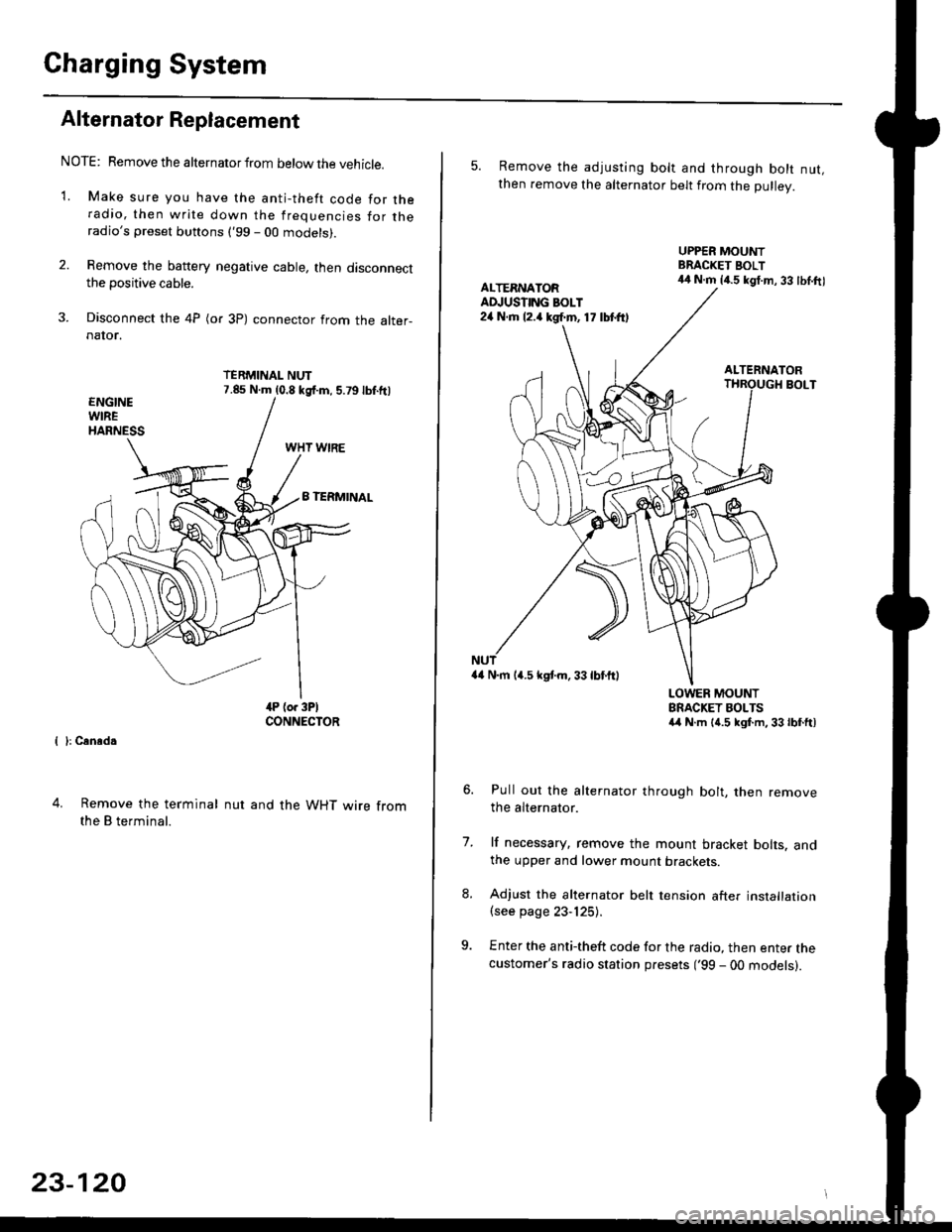
NOTE: Remove the alternator from below the vehicle.
'1. Make sure you have the anti-theft code for theradio, then write down the frequencies for theradio's preset buttons ('99 - 00 models).
2. Remove the battery negative cable, then disconnectthe positive cable.
3. Disconnect the 4P (or 3P) connector from the alter-naIor.
TERMINAL NUT7.85 N.m (0.8 kgf.m, 5.79lbf.ftl
{ }: Cansd.
4. Remove the terminal
the B terminal.
nut and the WHT wire from
23-120
5. Remove the adjusting bolt and through bolt nut,then remove the alternator belt from the Dullev.
UPPER MOUNTBRACKET BOLT44 N.m 14.5 kgt.m, 33 lbl.ftlALTERNATORAD.'USTING BOLT24 N.rh l2.a kgf.m, 17 lbtft)
ALTERNATORBOLT
a4 N.m 14.5 kstm.33lbf'ftl
LOWER MOUNTBRACKET BOLTSa4 N.m l{.5 kgf.m,33lbfft)
Pull out the alternator through bolt, then removethe alternator.
lf necessary, remove the mount bracket bolts. andthe upper and lower mount brackets
Adjust the alternator belt tension after installation(see page 23-125).
Enter the anti-theft code for the radio, then enter thecustomer's radio station presets ('99 - 00 models).
7.
Page 1591 of 2189
JRectifier Removal
1. Remove the four through bolts.
Heat the rear bearing seat with a 1,000 W hair drier
tor about five minutes (120 - 140'F, 50 - 60"C).
3. Separate the rear housing from the drive-end hous-
ing by inserting a flst tip screwdriver into the open-
ings and prying them a part. Be careful not to dam-
age the stator with the tip of the screwdraver.
Seoarate the rear housing and drive-end housing
with the stator attached to the rear housing.
DEIVE-END HOUSING
STATOR
{cont'd)
23-121
REAR HOUSING
Page 1592 of 2189

Charging System
Rectifier Removal (cont'd)
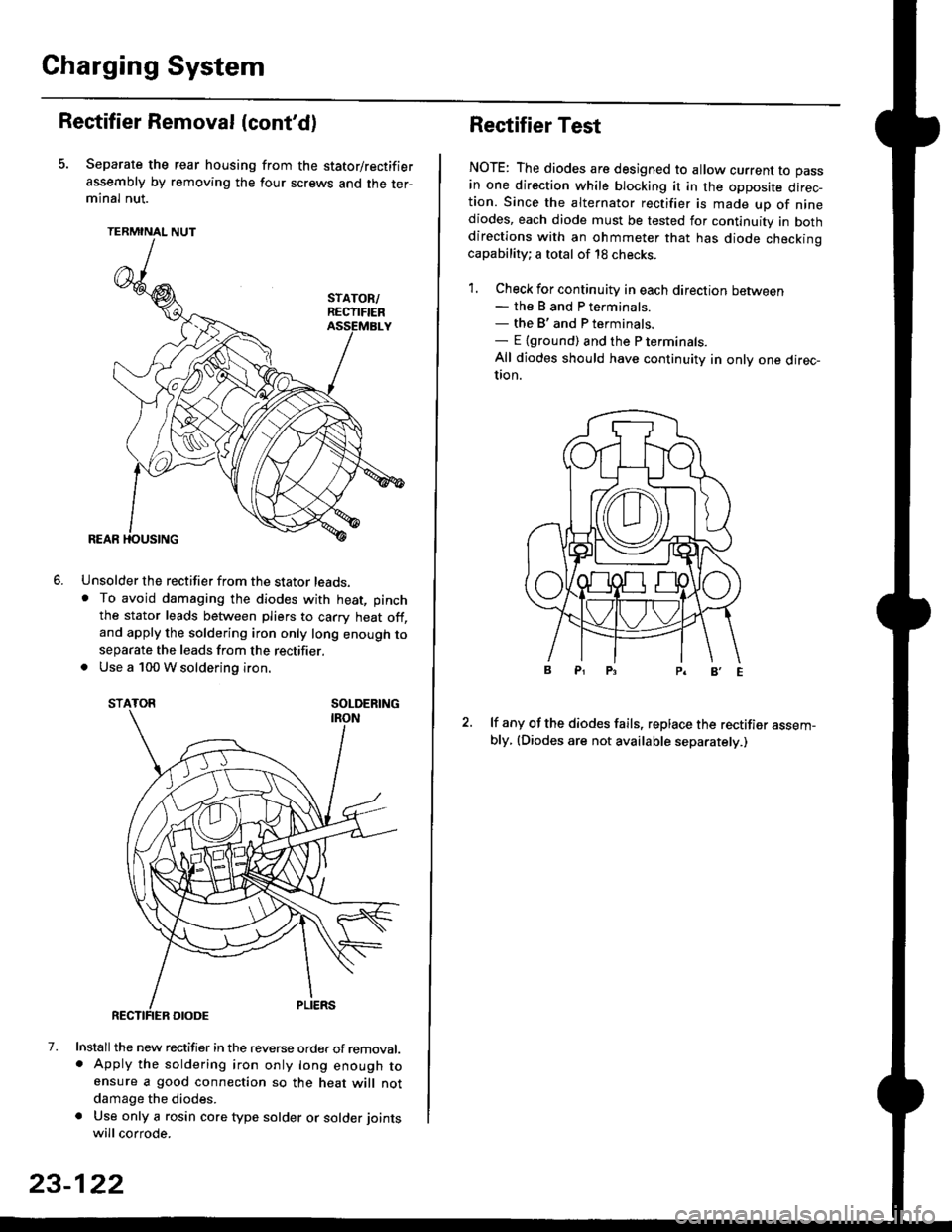
Separate the rear housing from the stator/rectifier
assembly by removing the four screws and the ter-minal nut.
TERMINAL NUT
Unsolder the rectifier from the stator leads,. To avoid damaging the diodes with heat, pinch
the stator leads between pliers to carry heat off,and apply the soldering iron only long enough toseparate the leads from the rectifier.. Use a 100 W soldering iron.
STATOR SOLDERING
7. Install the new rectifier in the reverse order of removal.. Apply the soldering iron only long enough toensure a good connection so the heat will notdamage the diodes.
a Use only a rosin core type solder or solder joints
will corrode.
6.
SOLDERING
23-122
Rectifier Test
NOTE: The diodes are designed to allow current to pass
in one direction while blocking it in the opposite direc-tion. Since the alternator rectifier is made up of ninediodes, each diode must be tested for continuity in bothdirections with an ohmmeter that has diode checkinocapability; a total of 18 checks.
1. Check for continuity in each direction between- the B and P terminals.- the B'and P terminals.- E {ground) and the P terminals.
All diodes should have continuity in only one direc-UOn.
lf any of the diodes fails, replace the rectifier assem-bly, (Diodes are not available separately.)
Page 1593 of 2189

JRotor Slip Ring Test
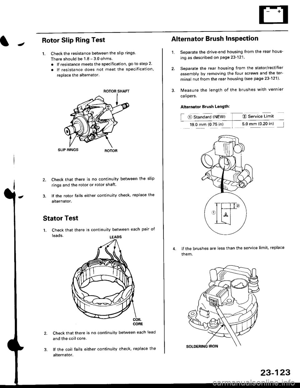
1. Check the resistance betlveen the slip rings
There should be 1 8 - 3 0 ohms
. lf resistance meets the specification, go to step 2.
. lf resistance does not meet the specification,
reolace the alternator'
SLIP BINGS
2. Check that there is no continuity between the slip
rings and the rotor or rotor shaft.
3. lf the rotor fails either continuity check, replace the
alternator.
Stator Test
'1. Check that there is continuity between each pair of
leads.
CORE
Check that there is no continuity between each lead
and the coil core.
lf the coil fails either continuity check, replace the
alternator.
ROTOR SHAFT
LEADS
1.
Alternator Brush InsPection
Separate the drive-end housing from the rear hous-
ing as described on page 23-121
Separate the rear housing from the stator/rectifier
assembly by removing the four screws and the ter-
minal nutfrom the rear housing {see page 23-121}
lvleasure the length of the brushes with vernrer
calrpers.
Alternator Brush Length:
O Standard {NEW} @ Service Limit
19.0 mm (0.75 in) 1 5.0 mm (0 20 in)
lf the brushes are less than the service limit, replace
them.
23-123
Page 1594 of 2189
Gharging System
Rear Bearing Replacement
1. Pull offthe rear bearing,
. Make sure the tips of the bearing puller jaws arethin enough to fit between the bearing and theslip rings.
. Do not reuse the bearing.
SLIP RINGSBEARING PULLER
Use a hand press to install the new bearing. Applypressure only on the inner race to avoid damaging
the bearino.
REAB BEARING
23-124
Alternator Reassembly
1. Push the brushes in, then insert a pin or drill bit(about 1.8 mm diameter) to hold them there.
Heat the rear bearing seat in the rear housing asdescribed on page 23-121. After heating, continueimmediately with assembling before the rear bear-ing seat cools completely,
Put the rear housing/stator assembly and drive-endhousing/rotor assembly together. tighten the fourthrough bolts and pull out the pin.
REARSTATOR ASSEMBLY
After assembling the alternator, turn the pulley byhand to make sure the rotor rotates smoothlv andwithout noise.
BRUSHES
THROUGH BOLT
Iq
%*z
BRUSH AOCESS HOI."E