1999 HONDA CIVIC linkage
[x] Cancel search: linkagePage 72 of 2189
ILubrication Points
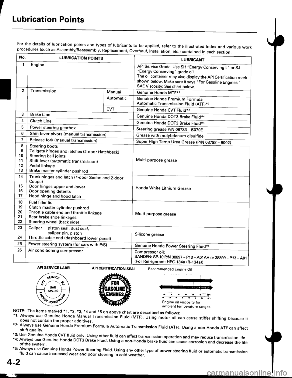
For the details of lubrication points and types of lubricants to be applied, refer to the lllustrated Index and various workprocedures (such as Assembly/Reassembly, Replacement, Overhaul. Installation, etc.) contained in each section.
No.LUBRICATION POINTS
Engine
LUBRICANT
"Energy Conserving" grade oil,The oil container may also display the Apl Certification markshown below. Make sure it says ,,For Gasoline Engines.,,SAE Viscosity: See chart below,
I
TransmissionManualGenuine Honda MTF*1
Genuine Honda Premium FormulaAutomatic Transmission Fluid (ATF)*,
Genuine Honda CVT Fluid*3
Genuine Honda DOT3 Brake Fluid*a
Automatic
CVT
3Brake Line
ClL,tci t""e4
I
Genuine Honda DOT3 Brake Fluid*aPower steering gearboxSteering grease P/N 08733 - BO70EShift lever pivots (manual transmission)Grease with molybdenum disulfide7-:ti
9
10'l'l
l3
14
't7
18
19
20
2122
Release fork (manual trancmi
Shift lever (automatic transmission)Pedal linkageBrake master cylinder pushrod
Super High Temp Urea crease (p/N 08798 - 9OO2)
i Multi-purpose grease
I
I
Honda White Lithium Grease
Multi-purpose grease
Silicone grease
@
Trunk hinges and latch (4-door Sedan and 2-doorCoupe)Door hinges upper and lowerDoor opening detentsHood hinge and hood latch-FUet T ter ttd
Clutch master cylinder pushrodThrottle cable end and throttle linkageRear brake shoe linkagesSteering wheel (back side)
23
E-
Caliper piston seal, dust seal,caliper pin. pistonThrottle cable end (dashboard lower panel)
Power steering system (for cars with p/S)
Air conditioning compressorComDressor oil:SANDEN: SPlo P/N 38897 - p13 -A01AH or 38899 - p13_ A01{For Refrigerant: HFC-134a (R-134a))
CERTIFICATION SEAL
ffi
NorE: The items m arked * 1, *2, +3, *4 and +5 on above chan are described as folows:*1: Always use Genuine Honda Manual Transmission Fluid (MTF). Using motor oil can cause stiffer shifting because itdoes not contain the proper additives.*2: Always use Genuine Honda premium Formula Automatic Transmission Fluid (ATF). Using a non-Honda ATF can affectshift quality.+3: Use Genuine Honda cVTfluid only usingotherfluid can affect tra nsmission operation and may reduce transmission life.*4: Always use Genuine Honda DoT3 Brake Fluid. Using a non-Honda brake fluid can cause corrosion and dec.ease the lifeof the svstem.*5: Always use Genuine Honda Power steering Fluid. using any other type of power steering fluid or automatrc transmissionfluid can cause increased wear and poor steering in cold weather.
4-2
Recommended Engine Oil
Engine oil viscosity forambrent temperature ranges
API SERVICE LABEL
Page 138 of 2189

Removal
Engine removal is not required for this procedure
!!!s@ Make sure iacks and salety stands are
f ta"eata"ea propetty and hoist brackets are attached to the
correct positions on the engine.
CAUTION:
. Use tender covels to avoid damaging painted sul-
faces.
o To avoid damage, unplug the wiling connectors
carefully while holding the connector portion to
avoid damage.
. To avoid damaging the cylinder head, wait until the
engine coolant temperature drops below 100"F
{38"C} before loossning the tetaining bolts.
NOTE:
o Mark all wiring and hoses to avoid misconnectlon
Also, be sure that they do not contact other wiring or
hoses, or interfere with other parts.
. Inspect the timing belt before removing the cylinder
h ead.
. Turnthe crankshaft pu lley so that the No. lpistonisat
top dead center (see Page 6-21)
'1. Disconnect the negative terminal from the battery'
Drain the engine coolant (see page'10-7).
a Remove the radiator cap to speed draining.
Remove the intake air duct and air cleaner housing
(see page 5 3).
Remove the mounting bolt and lock bolt. then
remove the power steering (P/S) pump belt and
pump (see page 5'5).
Loosen the idler pulley center nut and adjusting
bolt' then remove the air conditioning (A'lc) com-
pressor belt (see Page 5-6).
Loosen the mounting nut and lock bolt. then
remove the alternator belt (see page 6-19).
Remove the P/S pump bracket (see page 5-12).
3.
4.
2.
6.
1.
8. Remove the throttle cable by loosening the locknut,
then slip the cable end out of the throttle linkage
NOTE:
. Take care not to bend the cable when removing it
Always replace any kinked cable with a new one
. Adjust the throttle cable when installing (see sec-
tion 1 1).
D16Y7 engine:
Dl6Y5, Dl6Y8 engines:
THFOTTLECABLE
(cont'd)
6-27
LOCKNUT
CABLE
Page 178 of 2189
Cylinder Head
Removal (cont'd)
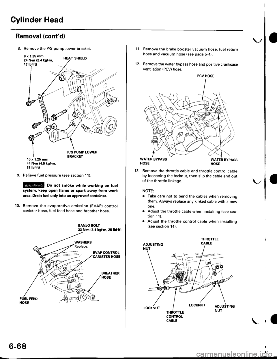
8. Remove the P/S pump lower bracket.
8 x 1.25 mm24 N.m 12.4 kgf.m,17 tbtftl
9.
T SHIELD
10.
P/S PUMP LOWERBRACKET10 x 1.25 mm44 N.m {4.5 kgf.m,33 tbf.frl
Relieve fuel pressure (see section l1).
@ Do not smok6 while working on fuel
system, keep open flam€ or spark away lrom work
ar€a, Drain fuelonly into an approved cortain€r.
Remove the evaporative emission (EVAP) control
canister hose, fuel feed hose and breather hose.
BANJO BOLT33 N.m (3.4 kgl.m.25 lbf.ftl
BREATHERHOSE
WASHERS
6-68
\.
11. Remove the brake booster vacuum hose, fuel return
hose and vacuum hose (see page 5 4).
12. Remove the water bypass hose and positive crankcase
ventilation (PCV) hose.
WATER BYPASSHOSEWATER EYPASSHOSE
Remove the throttle cable and throttle control cable
by loosening the locknut, then slip the cable end out
of the throftle linkage.
NOTE;
. Take care not to bend the cables when removing
them. Always replace any kinked cable with a new
one.
. Adjust the throttle cable when installing (see sec-
tion I I ),. Adjust the throttle control cable when installing(see section 14).
CONTROLCABLE
1a
PCV HOSE
Page 513 of 2189

lntake Air System
Air Cleaner (ACLI
NOTE: Do not clean the ACL element it with com-pressed air {except dry type).
D16Y5, D16Y8, 816A2 engine:
ACL ELEMENTNormal conditions:Replace air cleaner element every30,000 miles (48,000 km) or 24months whichever comes first.S€voae conditions:(Use normal scheduleexcept in dusty conditions)Replace every 15,OOOmiles (24,000 km)or 12 monthswhichever comes first.
D16Y7 engine:
ACL ELEMENTNormal conditions:Replace air cleaner element every30,000 miles (48,000 km) or 24months whichever comes first,Seve.s conditions:(Use normal schedule exceptin dusty conditions)Replace every l5,000
whichever comes first.
11-244
Throttle Cable
Inspection/Adiustment
1. Start the engine. Hold the engine at 3,000 rpm withno load (in Park or neutral) until the radiator fancomes on, then let it idle.
2. Check that the throftle cable operates smoothly withno binding or sticking. Repair as necessary.
3. Check cable free play at the throttle linkage. Cabledeflection shoutd be 10- l2 mm (3/B - 112 in.l.
D16Y5, D16Y8 engine:
CABLEBRACKETLOCKNUT
DEFLECTION10-12mm
BIA- 112 inl
D16Y7 engine:
LOCKNUT
DEFLECTION10- 12 mml3lA - lninl
Page 514 of 2189
\J
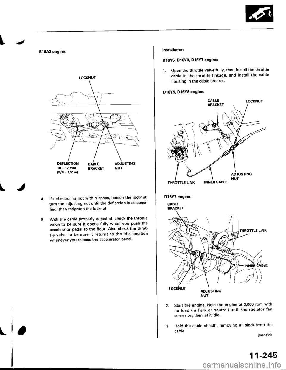
816A2 engine:
DEFLECTION10-12mmBla- 112inl
CABLE ADJUSTINGBRACKET NUT
t
lf deflection is not within specs' loosen the locknut'
turn the adjusting nut untilthe deflection is as speci-
fied, then retighten the locknut.
With the cable properly adiusted, check the thronle
valve to be sure it opens fully when you push the
accelerator pedal to the floor. Also check the throt-
tle valve to be sure it returns to the idle position
whenever you release the accelerator pedal'
LOCKNUT
lnstallation
Dl6Y5, Dr6Y8, D16Y, €ngine:
1. Open the throttle valve fully, then install the throttle
cable in the throttle linkage, and install the cable
housing in the cable bracket.
D16Y5, D16Y8 engins:
LOCKNUT
Start the engine. Hold the engine at 3,000 rpm with
no load (in Park or neutral) until the radiator fan
comes on, then let it idle.
Hold the cable sheath. removing all slack from the
caDle (cont'dl
11-245
Page 515 of 2189

Intake Air System
Throttle Cable (cont'dl
4. Set the locknut on the cable bracket. Adjust theadjusting nut so that its free play is O mm.
5. Bemove the cable sheath from the throttle bracket,reset the adjusting nut and tighten the locknut.
O16Y5, D16Y8 engino:
ADJUSTING NUT
9.8 N.m{1.0 kgl.m,1.2 tbt.ttl
DtGYT 6ngine:
11-246
816A2 engine:
1. Open the throttle valve fully, then install the throttlecable in the throttle linkage. and install the cablehousing in the cable bracket,
THROTTLE LINK
LOCKNUTADJUSTINGNUT
Start the engine. Hold the engine at 3.000 rpm withno load (in Park or neutral) until the radiator fancomes on, then let it idle.
Hold the throttle link to the throttle lever; thereshould be no clearance.
Hold the cable sheath, removing all slack from thecable.
Turn the adjusting nut untit it is 3 mm {1/8 in.) awayfrom the cable bracket,
LOCKNUT9.8 N.m(1.0 kgt m,7.2 tM.ttl
ADJUSTING NUT
Tighten the locknut. The cable deflection shouldnow be 10 - 12 mm l3/B - 1/2 in.). lf nor. seeInspection/Adjustment.
3 mm 11/8 in.)
Page 1057 of 2189
l.
t
Steering
Speciaf Tools ....."'.....17-2
Manual Steering
Component Locations
lndex ................ ....... 17-3
Inspection and Adiustment
Steering Operation "'......"............... 17-4
Rack Guide Adiustment ................... 17-5
*Steering Wheel
(See power steering section)
*Steering Column
(See power steering sectionl
Steering Gearbox
Removal ................. 17-5
Disassembly ......."" 17-7
ReassemblY ..'......... 17-9
lnstallation ............. 17-13
Power Steering
Component Locations
lndex "......."..... """' 17-15
System DescriPtion
Fluid Flow Diagram .........""............. 17'16
Steering Pump ............'... "........"'...-- 17 -17
Steering Gearbox .".................'...'.'.' 17-20
Troubleshooting
Generaf Troubleshooting ..........--.... 17'22
Noise and Vibration ......................... 17 -26
Ffuid Leaks .............17-28
Inspection and Adiustment
Steering Operation'......."'........'...... 1 7-30
Power Assist Check
With Vehicle Parked .."................ 17-30
Steering Linkage and Gearbox ....." 17-31
Pump Beft ...--.""".. 17-32
Rack Guide Adiustment .'.......'.......'. 17'33
Fluid Replacement .....'.."................. 17-33
Pump Pressure Check .............'....-. " 17 -34
'Steering Wheel
Removal .."'........'... 17-35
lnstallation ............. 17-35
Disassembly/Reassembly ......'.....'.' 17-36
*Steering Column
Removal/lnstallation ....'........... ---.... 17'37
lnspection .............. 17'38
Power Steering Hoses, Lines
Fluid Leakage Inspeetion ............'.... 17-39
Replacement ......".. 17-39
Power Steering PumP
Removal/lnstallation .'.'..'..'............. 17-40
Disassembly ".........17-41
fnspection .......---'." 17'42
Reassembly ..'.........17-44
Steering Gearbox
Removal ....'........."' 17'47
DisassemblY ..........' 17-49
Reassembly '........... 17-55
lnstallation ............. 17-65
Ball Joint Boot Replacement .......'.. 17-68
Ir/
lp
Page 1060 of 2189
Inspection and Adjustment
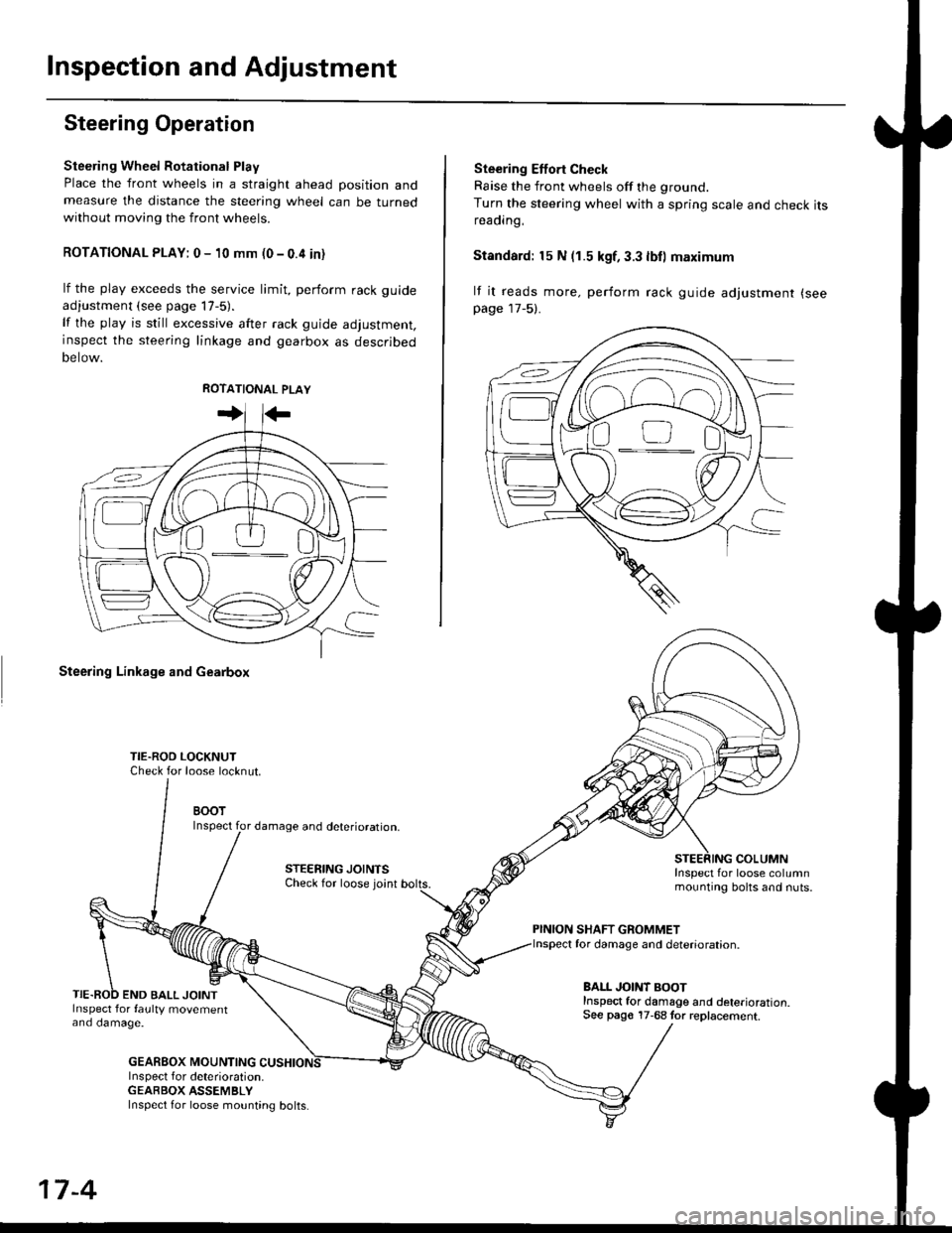
Steering Operation
Steering Wheel Rotational Play
Place the front wheels in a straight ahead position andmeasure the distance the steering wheel can be turnedwithout moving the front wheels.
ROTATIONAL PLAY: 0 - 10 mm (0 - 0.4 in)
lf the play exceeds the service limit, perform rack guide
adjustment (see page lT-5).
lf the play is still excessive after rack guide adjustment,inspect the steering linkage and gearbox as descrjbed
Detow.
Steering Linkage and Gearbox
TIE.ROO LOCKNUTCheck for loose locknut.
BOOTInspect for damage and deterioration.
STEERING JOINTSCheck for loose joint
END BALL JOINTInspect for faulty movementano oamage.
GEABBOX MOUNTINGInspect f or deterioration.GEABBOX ASSEMBLY
Ste€ring Effort Check
Raise the front wheels off the ground.
Turn the steering wheel with a spring scale and check itsreaorng,
Standard: 15 N (1.5 kgf, 3.3 lbll maximum
lf it reads more. perform rack guide adjustment (see
page 17-5).
COLUMNInspect for loose columnmounting bolts and nuts.
PINION SHAFT GROMMETfor damage and deterioration.
BALL JOINT BOOTInspect for damage and deterioration.See pago 17-68 tor replacement.
ao-\---------U
17-4
Inspect for loose mounting bolts.