Page 1387 of 2189
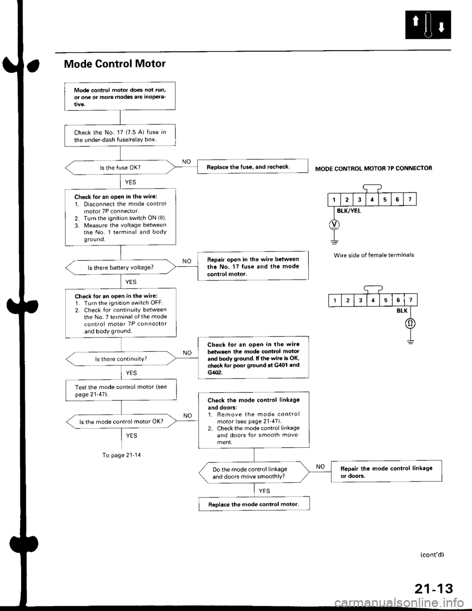
Mode Control Motor
To page 21-14
MODE CONTROL MOTOR 7P CONNECTOR
'1
I2I57
BLK/YEL
Wire side of female terminals
Mode control motor does not run,
or one of more modes are inoPela-
Check the No. '17 (7.5 A) fuse in
the under-dash fuse/relaY box.
Reolace the fuse, and recheck.
Check lor an open in the wire:
1. Disconnect the mode controlmotor 7P connector.2. Turn the ignition switch ON (ll).
3. Measure the voltage betweenthe No. l terminal and bodyg rou nd.
Repair open in the wire between
the No. 17 tuse and the mode
control motor.ls there batterY voltage?
Check {or an open in the wire:1. Turn the ignition switch OFF.
2. Check for continuity between
the No. 7 terminal of the mode
co nlrol motor 7P connector
and body ground.
Check for an open in the wire
batwe€n the mode contrcl motol
and body ground. lf the wir€ is OK,check for poor gtound at G/U)l and
G402.
ls there continuity?
Test the mode control motor (see
page21-471.Check the mod€ control linkage
and doors:1. Bemove the mode controlmotor (see page 21-47).2. Check the mode control linkageand doors for smooth move
ls the mode control motor OK?
Do the mode control linkageand doors move smoothlY?
Reolace the mode control motor,
I34561
BLK
[]
(cont'd)
Page 1390 of 2189
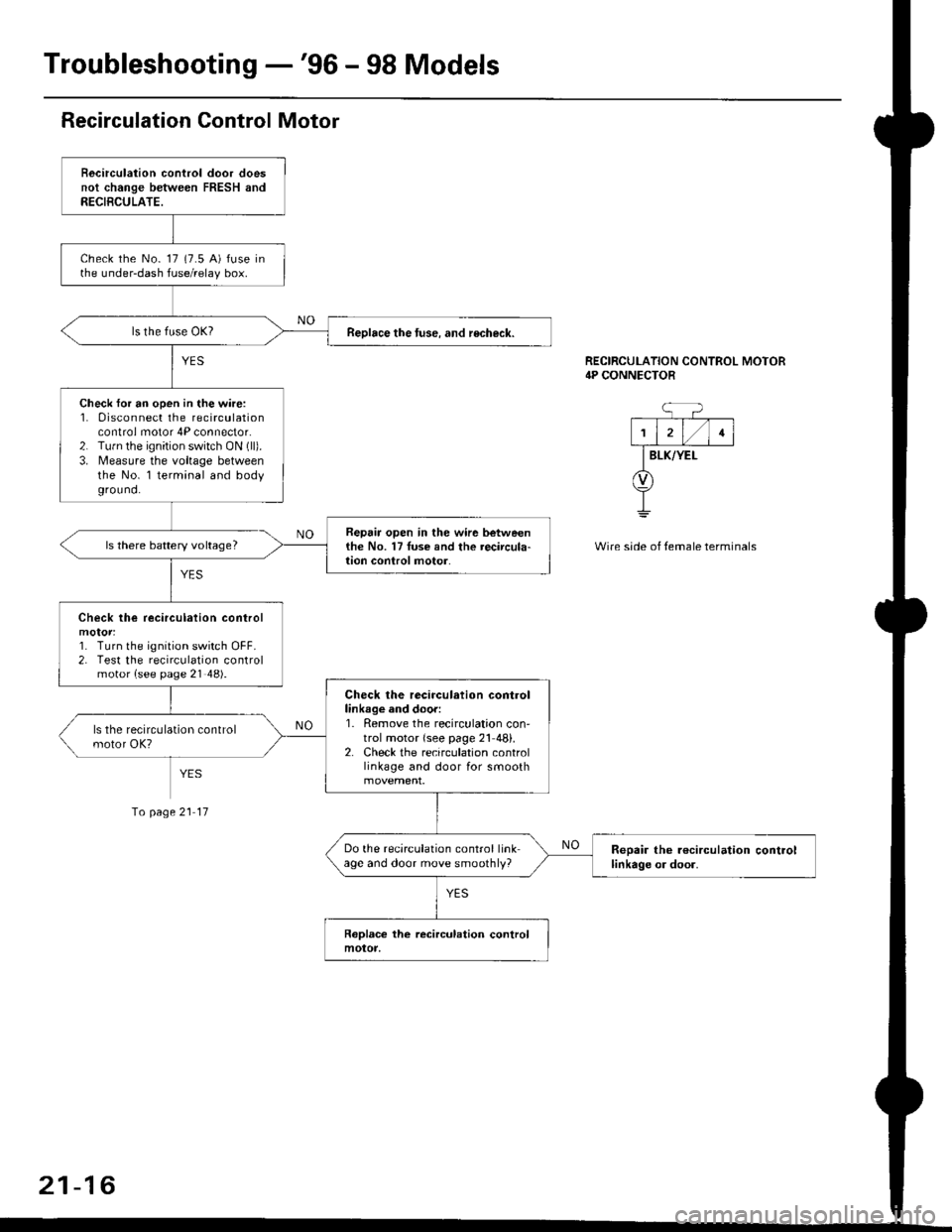
Troubleshooting -'96 - 98 Models
Recirculation Control Motor
Becirculation control door doesnot change between FRESH andRECIBCULATE.
check the No- 17 (7.5 A) fuse inthe under-dash fuse/relay box.
Reolace the tuse. and recheck.
Check for an open in the wire:1. 0isconnect the recirculationcontrol motor 4P connector.2. Tu.n the ignition switch ON (ll).
3. Measure the voltage betweenthe No. l terminal and bodyground.
Repair open in the wir6 betweenthe No. 17Iuse and the recircula-lion conlrol motor.ls there battery voltage?
Check lhe recirculation control
1. Turn the ignition switch OFF.2. Test the recirculation controlmotor {see page 21 48).
Check the recirculation controllinkage and door:1. Remove the recirculation con'trol motor {see page 21 48}.2. Check the recirculation controllinkage and door for smooth
Do the recirculation control linkage and door move smoothly?Reoair the r€circulation controllinkage or door.
RECIRCULATION CONTROL MOTOR4P CONNECTOR
BLK/YEI-
Wire side of temale terminals
Io page 21 17
21-16
Page 1395 of 2189
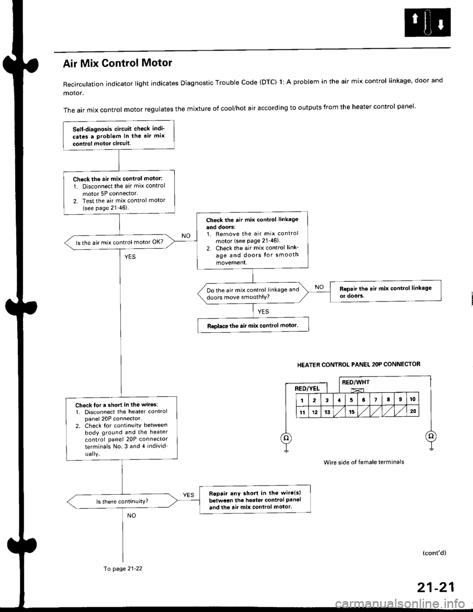
Air Mix Gontrol Motor
Recirculation indicator light indicates Diagnostic Trouble code (DTC) 1l A problem in the air mix control linkage, door and
motor.
The air mix control motor regulates the mixture of cool/hot air according to outputs from the heater control panel'
Self-diagnosis circuit check indi'
cates a Problem in the air mix
conlrol motor circuit,
Check th6 aii mix conirol motor:
1. Disconnect the air mix control
motor 5P connector.
2. Test the air mix control motor(see page 21-46).
check the air mix control linkage
and doors:1. Remove the air mix control
motor (see Page 21-46)
2. Check the air mix control link-
age and doors lor smooth
movement.
ls the air mix control motor OK?
Do the air mix control linkage and
doors move smoolhlY?
R€olace the air mix control motor'
Check tor a short in the wiles:
1. Disconnect the heater controlpanel 20P connector-2. Check for continuitY between
body ground and the heater
control panel 20P connector
terminals No.3 and 4 individ'
uaIY.
Ropair any short in th€ wire{s}
betweon the heater control Paneland the air mix control motor'
HEATER CONTROL PANEL 2OP CONNECTOR
RED/WHTRED/YEL
Wire side ot female terminals
(cont'd)
fo page 21-22
21-21
Page 1397 of 2189
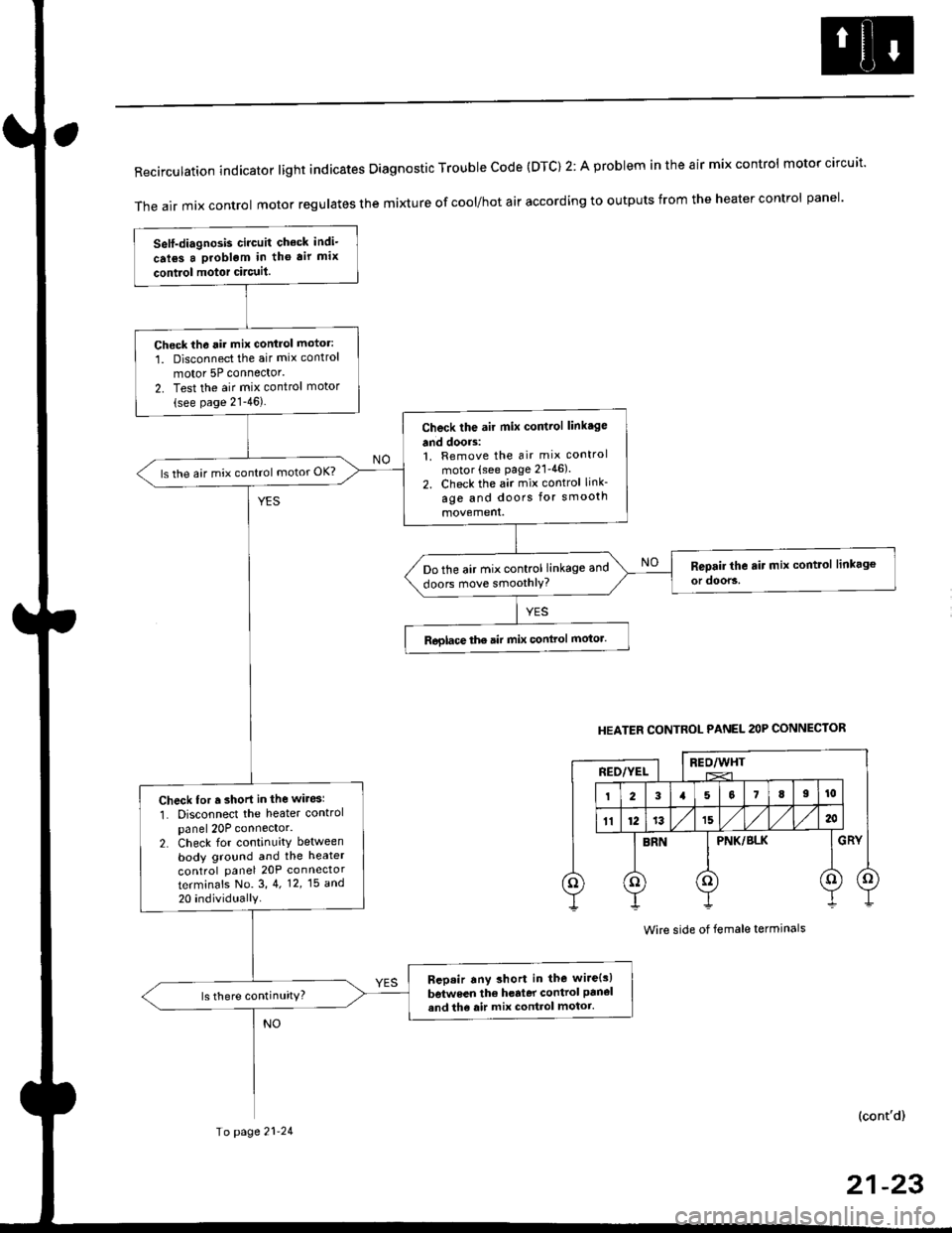
RecirculationindicatorIightindicatesDiagnosticTroublecode(DTc)2:AprobIemintheairmixcontro|motorcircuit.
The air mix control motor regutates the mi)dure of cool/hot air according to outputs from the heater control panel'
Self-diagnosis circuit check indi-
crl6s a problgm in tho air mix
contiol motor circuit.
Check th6 rir mix control motor:
1. Disconnect the air mix control
motor 5P connector'
2. Test the air mix control motor(see page 21-46).
Check the air mix control linkage
and doors:1. Remove the air mix control
motor (see page 21'46).
2. Check the air mix control link-
age and doors for smooth
ls the air mix control motor OK?
Do the air mix control linkage and
doors move smoothlY?
Roglace the air mix conlrol motor.
Check for r short in the wiresl
1. Disconnect the heater controlpanel 20P connector.2. Check for continuity between
body ground and the heater
control panel 20P connector
terminafs No. 3,4. 12,15 a^d
20 individually
Bep.ir any short in the wire{s)
between the h€rter control panel
and th6 air mix control motor.ls there continuity?
HEATER CONTROL PANEL 2OP CONNECTOR
BEO/WHTREO/YEL
PNK/BLK
Wire side of female terminals
(cont'd)
Io page 21-24
21-23
Page 1399 of 2189
![HONDA CIVIC 1999 6.G Workshop Manual Mode control motor does not run.
or one or more modes arc inope]a-
tive.
Check the No. 17 (7.5 A) fuse in
the under-dash fuse/relay box.
Replace the Iuse. and recheck.
Check for an open in the wire:
1 HONDA CIVIC 1999 6.G Workshop Manual Mode control motor does not run.
or one or more modes arc inope]a-
tive.
Check the No. 17 (7.5 A) fuse in
the under-dash fuse/relay box.
Replace the Iuse. and recheck.
Check for an open in the wire:
1](/manual-img/13/6068/w960_6068-1398.png)
Mode control motor does not run.
or one or more modes arc inope]a-
tive.
Check the No. 17 (7.5 A) fuse in
the under-dash fuse/relay box.
Replace the Iuse. and recheck.
Check for an open in the wire:
1. Disconnect the mode control
motor 7P connector,
2. Turn the ignition switch ON (ll)-
3. MeasLrre the voltage between
the No. 1 terminal of themode control motor 7P con
nector and body ground
Repair open in the wire between
the No. 17 luse and lhe mode
control motor.ls there battery voltage?
Check the mode control motor:
1- Turn the ignition switch OFF
2, Test the mode control motor(see page 21 47).Check lhe mode control linkage
and doors:1. Remove the mode controlmotor (see page 21 47).
2. Check the mode control linkage
and doors for smooth move
ls the mode control motor OK?
Do the mode control linkage
and doors move smoothlY?
ReDlace the mode control motor'
Check for a short to Power in the
wires:1. Iurn the,gnitjon switch ON(ll).
2, Disconnect the heater controlpanel20P connector.3. Check for voltage betweenthe No. 2, 5, 6, 7, I and 9 ter'minals of the heater controlpanel 20P connector andbody ground individuallY.Repair shorl to power in the
wire{sl between the heater con-
trol oanel and the mode controlmotor. This short also damagesthe heater control Pan6l. RePair
the short to power before replac'ing the heater control Panel
ls lhere any voltage?
MODE CONTROL MOTOR 7P CONNECTOR
t2315
BLK/YEL
Wire side of female terminals
HEATER CONIROL PANEL 2OP CONNECTOR
Wire side of female terminals
NO
(cont'd)
21-25Io page 21 26
Page 1401 of 2189
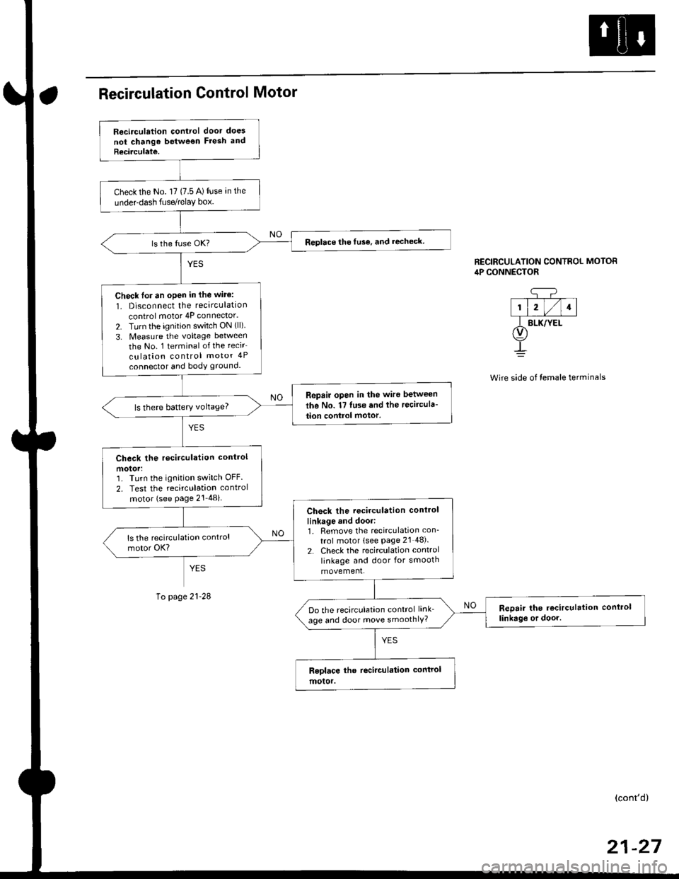
Recirculation control door does
not chango betwe€n Fresh and
Recirculate.
Check the No. l7 (7.5 A) fuse an the
underdash fuse/relay box.
Replace the fuse, and recheck.
Check lor an oPen in the wite:
1. Disconnect the recirculation
control motor 4P connector.
2. Turn the ignition switch ON (ll)
3. Measure the voltage between
the No. 1 terminal of the recir
culation control motor 4P
connector and body ground.
Repair open in the wire between
the No. 17 luse and lhe recircula-
tion control motor.ls there battery voltage?
Check the rccirculation control
motorr']� Turn the ignition switch OFF.
2. Test the recirculation control
motor (see Page 21 48i
Check the recirculation control
linkage and door:1. Remove the recirculation con_
trol motor lsee Page 2l 48).
2. Check the recirculation control
linkage and door for smooth
movement.
Reoair the recirculation conlrol
linkag€ or door.Do the recirculation control link_
age and door move smoothlY?
CONTROL MOTOR
side of temale terminals
RECIRCULATION CONTRC,lP CONNECTOR
q-?--T--T--T-|1l2l/l1l
f BLK/YEt(v)
!
page
(cont'd)
Page 1412 of 2189
Blower Unit
Overhaul
NOTE:
RECIRCULATIONCONTROL MOTORTest, page 21-48
aBefore reassembly. make sure that the recirculation control door and linkage move smoothly without binding.
When attaching the recirculation control motor, make sure its positioning will not allow the recirculation control door
to be pulled too far.
After aftaching the recirculation control motor, connect power and ground, and watch the movement of the recircula-
tion control door.
BLOWERTest, page 2'l 9{'96 - 98 modebl
POWER TRANSISTOR l'99 - 00 modeblTest, page 21-50
Test, page 21'10 ('96 98 models) orpage 21'31 ('99 00 models)
m
MOTOR
2134
Page 1420 of 2189
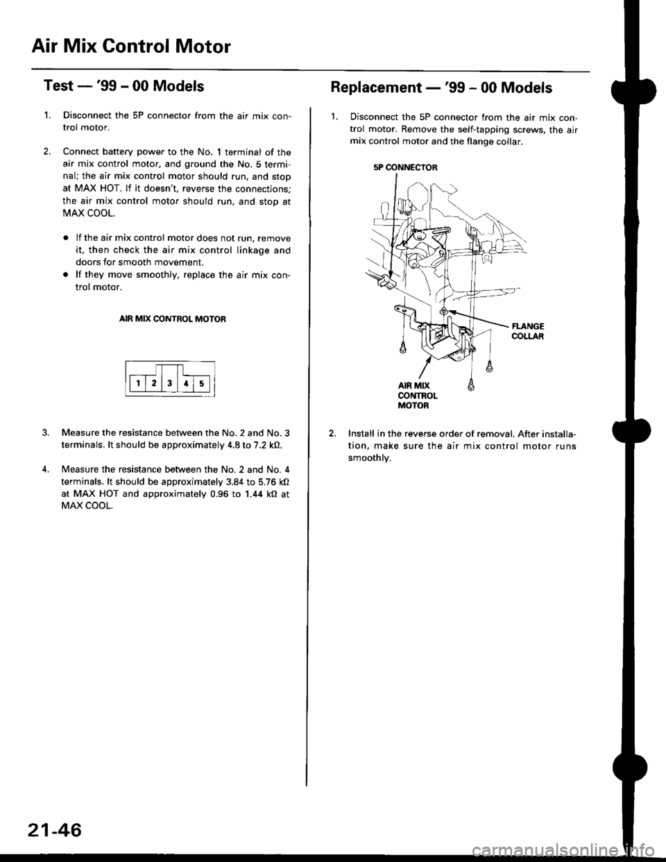
Air Mix Gontrol Motor
't.
Test -'99 - 00 Models
Disconnect the 5P connector from the air mix con-
trol motor.
Connect battery power to the No. 1 terminal of the
air mix control motor, and ground the No. 5 termi,
nal; the air mix control motor should run, and stop
at MAX HOT. lf it doesn't, reverse the connections;
the air mix control motor should run, and stop at
MAX COOL.
lf the air mix control motor does not run, remove
it, then check the air mix control linkage and
doors for smooth movement.
lf they move smoothly, replace the air mix con-
trol motor.
AIR MIX CONTROL MOTOR
Measure the resistance between the No.2 and No.3
terminals. lt should be approximately 4.8 to 7.2 kO.
Measure the resistance between the No. 2 and No. 4
terminals. lt should be approximately 3.84 to 5.76 kO
at MAX HOT and approximately 0.96 to 1.44 kO at
MAX COOL.
21-46
5P OONNECYOB
Replacement -'99 - 00 Models
1, Disconnect the 5P connector from the air mix con-
trol motor. Remove the self-tapping screws, the airmix control motor and the flange collar.
CONTROLMOTOR
Install in the reverse order of removal. After installa-
tion, make sure the air mix control motor runs
smoothly.