Page 1595 of 2189

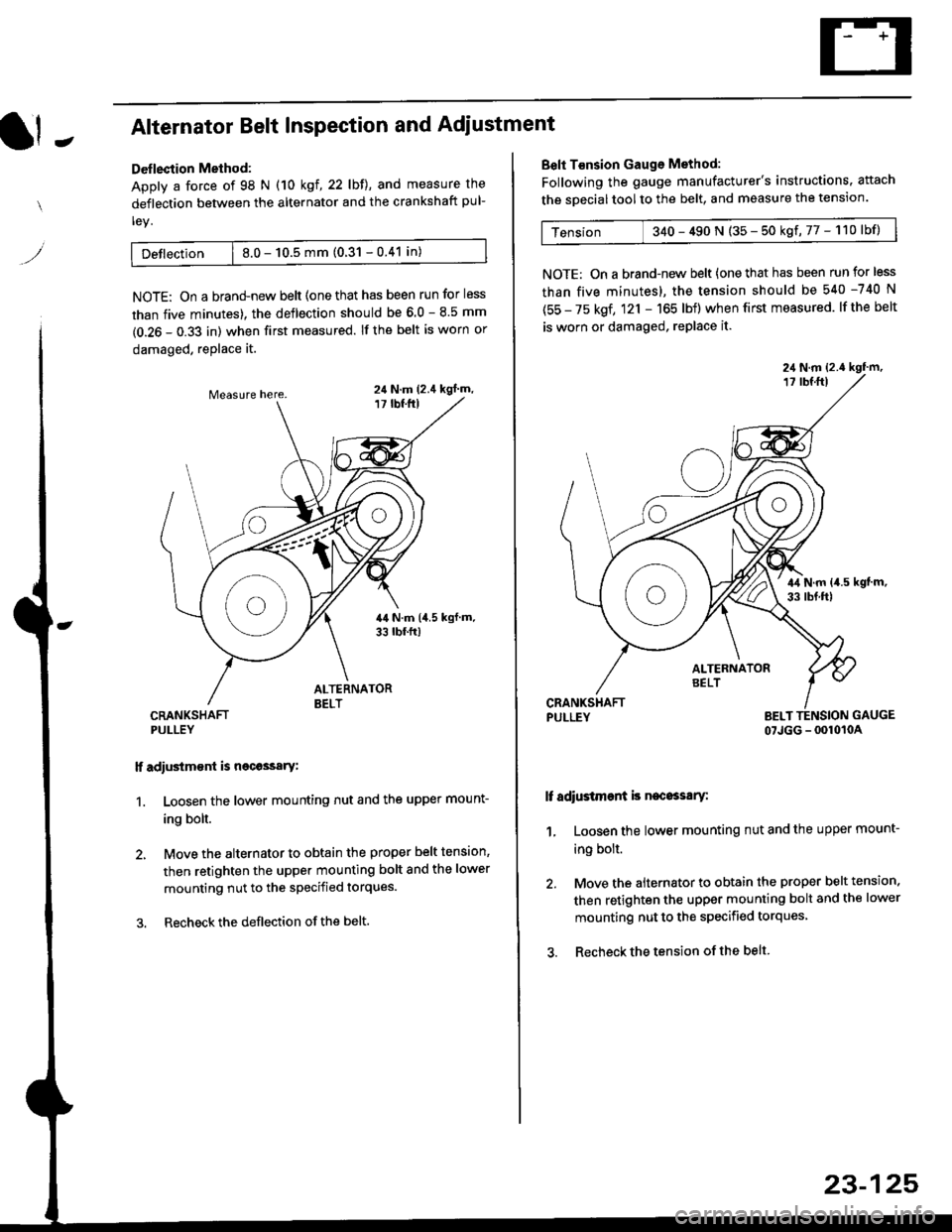
It -Alternator Belt Inspection and Adiustment
Deflection Method:
Apply a force of 98 N (10 kgl,22lbll, and measure the
deflection between the alternator and the crankshaft pul-
ley.
Detlection | 8.0 - 10.5 mm (0.31 - 0.41 in)
NOTE: On a brand-new belt {one that has been run for less
than five minutes). the deflection should be 6.0 - 8.5 mm
(0.26 - 0.33 in) when first measured. If the belt is worn or
damaged, replace it.
CRANKSHAFTPULLEY
lf adiustm€nt is necossary:
1. Loosen the lower mounting nut and the upper mount-
ing bolt.
2, Move the alternator to obtain the proper belt tension,
then retighten the upper mounting bolt and the lower
mounting nut to the specified torques.
3. Recheckthe deflection ofthe belt.
24 N.m (2.4 kgl m,
Belt T€nsion Gauge Method:
Following the gauge manufacturer's instructions. attach
the soecial tool to the belt, and measure the tension.
Tension 340 - 490 N (35 - 50 kgf,77 - 110lbf)
NOTE: On a brand-new belt {one that has been run for less
than five minutes), the tension should be 540 -740 N
(55 - 75 kgf, 121 - 165 lbf) when first measured. lf the belt
is worn or damaged, replace it.
PULLEY BELT TENSION GAUGE
07JGG - 0010104
It adiustment is necossary:
1, Loosen the lower mounting nut and the upper mount-
ing bolt.
2. Move the alternator to obtain the proper belt tension.
then retighten the upper mounting bolt and the lower
mounting nut to the specified torques
3. Recheck the tension of the belt
23-125
Page 1596 of 2189
Fan Controls
Component Location Index
UNDER.HOOO
CONDENSER FAN RELAYTest, page 23-87
RADIATOR FAN RELAYTest, page 23 87
CONDENSERFAN MOTOR
TOR FAN MOTORRemoval, section 10
ENGINE COOLANTTEMPERATURE (ECTI
swtTcHRemoval, section 10Test, section l0
t lt lt lt tt l
tlTtlnr-l
mU!L-Jfl_l'1 - f-t t-_l -
I L--J L__J LJ f-----"1
o
^o
o"l
23-126
Page 1598 of 2189
Gauge Assembly
Component Location Index
SRS components are located in this area. Review the SRS component locations, precautions, and procedures in the SRS
section (24) before performing repairs or service.
6x1.0mm9.8 N.m 11.0 kgf.m,22lbt.lrl
VEHICLE SPEED SENSOR {VSS)Troubleshooting, page 23-1 40
GAUGE ASSEMBLYGau ge/lndicator/TerminalLocation Index, page 23-129Removal, page 23-135Bulb Location, page 23-136Disassembly, page 23 138
PARKING BRAKE SWITCH
FLUIO LEVEL SW]TCH
23-128
ENGINE OIL PR€SSURE SWITCH
Page 1599 of 2189
JGau ge/lndicator/Terminal
With tachometer;
CONNECTOR "A"
{A/T GEAR POSITION INDICATOR}
Location lndex
CONNECTOR "8"
{GAUGE and INOICATOR)CONNECTOB "C"
CONNECTOR "D"
{ABS INDICATORI
SPEEDOMETER:Indicates 60 km/h at 637 rpm or
60 mph at 1,025 rpm o{thevehicle speed sensor (VSS).
A/T GEAR POSITIONINDICATORSee page 23 149
TACHOMETER:Indicates 100 rpm at200 pulses per minuteol the ignition controlmodule (lCMi.FUEL GAUGEENGINE COOLANT TEMPERATURE (ECT) GAUGE
(cont'd)
23-129
(GAUGE end INDICATORI
A1-----------+816
JlltlllulllllrL
c1 --------->c13
1ililil{ilrL
oooo o 0006^
)og @ @ o^o @ )'l |. o
Fl- - -> F5E1_ _ -->E5D1- --+05
oo/ \oo
Gauge/Sending Unit Test, page 23-142
Page 1892 of 2189
PGM-FI (All '9G'98 Models except D16B5; '99 D16Y5 with MiT)
- D16Y5 Engine
23-12
>r4
Page 1929 of 2189
A/T Gontrols ('96-'98 CVT) (conrd)
sfr
Dl0
YEUALU
@
I J
-'u-.'-.i - - -
I 3X3'5"
L]Sffiflulilir:
lLlftT:l,', "*,
3=:. fierminalslT-20)
*l
v56
r+
r andLights
"," I
;I
-JI!.
br
iee Dash
vtEw 56
IISs€ PowerDisfibution,page 10.6.Se€ PGIV-FI,page 23-12.See Dash arConsole Ligl
I FEo/ELK
lazIMANIFOLDABSOLUTEPRESSURE(MAP}
il'-
4o
(
REO/ELK-{ i["r.r,
RED/BLK
cl't5fferminals8n4)
wEw 3a
#.1 !3"" r,
c'l31PHOfO 85vtEw 59
1lc410
vtEw 35
Se€ GroundDistribution,page 1+7.
ORN/BLK
Dl1D12
a
-----1 ENGINE
I l-c_qllFgL
I l8l,:'�,T* lffiff" iF!&i:'
L_"S.f___ __y,' _j,ii!,J?"*
a
i
--r3 - -.
:F.
- - -.-o ,'i6i I rRANsMrssroN
I TP MAP
i iln'o, ;;;' iiaicato, i[f[!!! ftcM)
I input input conkol IVie-Jo:e'-L - - -- - - - - - - - - - - J
39-6
ir=l*--:*"ii*lF.?}t?''------JvtEwTa
\